
Topographically grooved gel inserts for aligning epithelial cells during air–liquid-interface culture†‡
John P.
Soleas
ab,
Thomas K.
Waddell
*abc and
Alison P.
McGuigan
*cd
aInstitute of Medical Science, University of Toronto, 200 College St., Toronto, ON M5S 3E5, Canada
bLatner Thoracic Surgery Research Laboratories and the McEwen Centre for Regenerative Medicine, Toronto General Hospital, 200 College St., Toronto, ON M5S 3E5, Canada
cInstitute of Biomaterials and Biomedical Engineering, University of Toronto, 200 College St., Toronto, ON M5S 3E5, Canada
dDepartment of Chemical Engineering and Applied Chemistry, University of Toronto, 200 College St., Toronto, ON M5S 3E5, Canada. E-mail: alison.mcguigan@utoronto.ca; tom.waddell@uhn.ca; Tel: +1 416 978 7552
First published on 9th September 2014
Abstract
Epithelial tissues are a critical component of all tubular organs. Engineering artificial epithelium requires an understanding of the polarization of epithelia: both apicobasal and in a planar fashion. Air liquid interface (ALI) culture is typically used to generate apicobasal polarized airway epithelium in vitro; however, this approach does not provide any signalling cues to induce morphological planar polarization of the generated epithelial layer. Here we describe a microgrooved gelatin hydrogel insert that can induce alignment of confluent epithelial cell sheets under ALI conditions to induce both apicobasal and morphologically planar polarized epithelium. Microgrooves are imprinted into the surface of the gelatin insert using elastomeric stamps moulded from a diffraction grating film and gels are stabilized by crosslinking with glutaraldehyde. We show that microgrooved gelatin inserts produce alignment of 3T3 fibroblasts and a number of epithelial cell lines (ARPE-19, BEAS2B and IMCD3 cells). Furthermore, we show that BEAS2B apicobasally polarize and form a similar density of cilia on both gelatin inserts and standard transwell filters used for ALI culture but that as apicobasal polarization progresses cell alignment on the grooves is lost. Our method provides a simple strategy that can easily be adopted by labs without microfabrication expertise for manipulating epithelial organization in transwell culture and studying the interplay of various polarization forces.
Introduction
Epithelial tissues line the luminal compartment of all tubular organs and are critical for their function.1 As with other tissues, correct organization of the tissue structure is important for achieving appropriate tissue function. Epithelial organization is diverse and broadly is divided into simple, stratified, and pseudostratified types.2 A classic feature of all epithelium is a polarization in the apicobasal axis of the cell3 which leads to the development of differential features and properties at apical and basal membrane locations within the cells. In addition to apicobasal polarization, epithelia are also often polarized in the planar axis of the tissue, such as directional alignment (morphological planar polarization), or planar polarization of the planar cell polarity signaling proteins.4 Morphological planar polarization results in cell elongation along the planar axis. The process of morphological planar polarization often leads to the alignment of actin or microtubule based structures within the epithelial cells that are critical for function. For example, in airway epithelium, planar polarization produces alignment of cilia, tubulin-based protrusions from the apical surface of ciliated epithelial cells.5 This alignment is necessary for appropriate mucus clearance from the airway.6 As another example, pigmented retinal epithelia are aligned in a morphological planar fashion to produce optical transparency.1,7 Generating both correctly organized, and correctly polarized epithelium is critical for creating functional-engineered epithelial tissue.The gold standard method to construct polarized airway epithelium in vitro is the air liquid interface (ALI) culture system.8 In ALI system, cells are grown on a permeable, transwell membrane insert that allows nutrient media to be supplied to the apical or basal surface of the cells. After a confluent monolayer is established, an ‘air-lift’ procedure is carried out, wherein the media from the apical compartment is aspirated. Thus, the cell monolayer is apically exposed to only a very thin liquid layer to keep the cells hydrated, and basally is supplied with media. These conditions promote apicobasal polarization and maturation of the growing airway epithelium. Maturation is primarily seen through ciliogenesis and tight junction formation.8 While this culture method produces predictable apicobasal polarization of the epithelial cells it does not provide any signalling cues to induce morphological planar organization or polarization of the generated epithelial layer.9,10 For example, cilia in airway epithelial ALI cultures are not aligned or coordinated in a linear fashion.11–13 In fact, despite the importance of morphological planar polarization, strategies to control the morphological planar polarization of epithelial cells in culture, and how this affects apicobasal polarization remains relatively unexplored.
A common strategy for aligning cell organization in engineered tissues is to culture cells on materials containing instructive, topographic features such as grooves.14–19 Previous work has shown that nano- and microscale topography causes morphological cell alignment or cytoskeletal alignment in a wide variety of cell types15,20–22 including some epithelial cells.14,23,24 For example, a number of studies have characterized the response of corneal epithelial cells on nanogroove topography,14,25–27 and have shown that corneal epithelial cells14,23,24 can be morphologically planar polarized on nanogrooves. Teixeira and colleagues14 assessed the effects of nanogrooved silicon oxide substrates on the alignment of human corneal epithelium and found that they aligned and elongated in the direction of the grooves (depth of 600 nm and pitch of 400 nm). Teixeira et al. (2006) also found that the corneal epithelial cells were more affected by the depth of the groove than their pitch. The minimum pitch to observe cell alignment in human corneal epithelial cells was in the range of 90–140 nm with depths in the range of 180–200 nm.25 Corneal epithelial cell behaviour has also been studied on micron-scale grooves. Dalton and colleagues23 used polystyrene based microgrooves of varying depths and groove widths to assess bovine corneal epithelial alignment. Similar to nanogrooves, they found that changing the groove depth had a greater effect on migration than altering groove width. Further, the actin cytoskeleton appeared to align in the direction of the microgrooves. While these studies clearly demonstrate a responsiveness of epithelial cells to topography, all were performed on solid substrates that do not allow diffusion of nutrients from the basal side of the cell in the same way a transwell insert allows. These substrates do not allow apicobasal polarization of the cells using ALI culture. Currently, there are no reports that have provided planar polarization cues to align epithelial cells, and potentially cilia, while concurrently maintaining the ALI culture conditions necessary to produce apicobasal polarization of the cells. Recently, work from Nealey also demonstrated the alignment of single corneal epithelial cells on RGD-functionalized poly(ethylene glycol) diacrylate hydrogels containing 300 nm grooves28 suggesting that hydrogel grooves can instruct cell alignment, at least for single cells. We therefore set out to develop a hydrogel-based strategy to expose sheets of confluent epithelial cells to grooved topographic alignment cues under ALI conditions that allow apicobasal polarization and the formation of cilia.
This report describes the development of a topographically patterned hydrogel insert that can be combined with a standard transwell filter insert to align epithelial cells under the culture conditions necessary for polarization and maturation. Using this insert we studied the effect of grooved topographic cues on cytoskeletal alignment and the impact of the induced alignment on subsequent apicobasal polarization of epithelium under ALI conditions. Specifically we generated a microgrooved gelatin insert by molding the surface of a gelatin layer using a topographically patterned elastomeric stamp. By imprinting our topographic features into a hydrogel insert, nutrients could still be delivered to the basal side of epithelial cells to promote polarization. We show that a number of epithelial cell lines align either their whole cell bodies, cytoskeletal actin, or nuclei parallel to the grooves when grown on the gelatin inserts. Here we used cell alignment as a read out of morphological planar polarization. We also found that cells polarize and generate cilia normally on gel inserts but that, surprisingly, cell alignment was lost after 24 hours in ALI culture, as the epithelial sheet organization induced by apicobasal polarization appears to override morphological planar polarization signals provided from both shallow and deep grooves. Our microgrooved insert provides a new tool that will enable tissue engineers and other scientists to further explore the relationship between epithelial organizational cues and cell sheet polarization.
Experimental
Cell culture
Experiments were done using the human epithelial cell lines ARPE-19 (retinal epithelium), IMCD3 (kidney epithelium), and BEAS2B (bronchial epithelium) and the mouse fibroblast cell line NIH 3T3 cells. All cells were from the American Type Culture Collection (ATCC), Manassas, Virginia, USA. ARPE19, IMCD3 and BEAS2B were maintained in growth medium (Dulbecco's modified Eagle Medium [DMEM]/F12 (Invitrogen, Grand Island, NY, USA), 10% fetal bovine serum (PAA Laboratories Inc., Etobicoke, Ontario, Canada), and 1 μg ml−1 penicillin and streptomycin (Sigma Aldrich, St. Louis, MO, USA). NIH-3T3 were maintained in DMEM, supplemented with 10% fetal bovine serum and 1 μg ml−1 penicillin and streptomycin.Generation of microgrooved insert
Fig. 1 summarizes our strategy to create reproducible microgroove gelatin hydrogel inserts. We wanted to create a simple strategy to generate inserts that would be widely accessible to scientists without microfabrication experience. We first created a stamp from the synthetic elastomeric polymer, polydimethylsiloxane (PDMS), by replica molding on a silanized diffraction grating (Edmund Optics, Barrington, NJ), with known microgroove topography (1 μm pitch). This was done because the grating itself was fragile and easily scratched whereas the PDMS replica was tough and significantly more resistant to scratching during repeated use. The grating surface was silanized with (tridecafluoro-1,1,2,2,Tetrahydro Octyl 1)-trichlorosilane and then coated with a 1![[thin space (1/6-em)]](https://www.rsc.org/images/entities/char_2009.gif) :10 mix of PDMS crosslinker:elastomer (Dow Corning Corporation, Midland, Mi., USA). The film was then placed in a vacuum for twenty minutes and allowed to cure overnight at 60 °C. After curing, the PDMS layer was peeled from the diffraction grating and an 8.0 mm biopsy punch (Fray Product Corporation, Buffalo, New York, USA) was used to cut-out a circular-microgrooved PDMS stamp. Microgrooved PDMS stamps were sterilized in UV light for 30 minutes before further use.
:10 mix of PDMS crosslinker:elastomer (Dow Corning Corporation, Midland, Mi., USA). The film was then placed in a vacuum for twenty minutes and allowed to cure overnight at 60 °C. After curing, the PDMS layer was peeled from the diffraction grating and an 8.0 mm biopsy punch (Fray Product Corporation, Buffalo, New York, USA) was used to cut-out a circular-microgrooved PDMS stamp. Microgrooved PDMS stamps were sterilized in UV light for 30 minutes before further use.
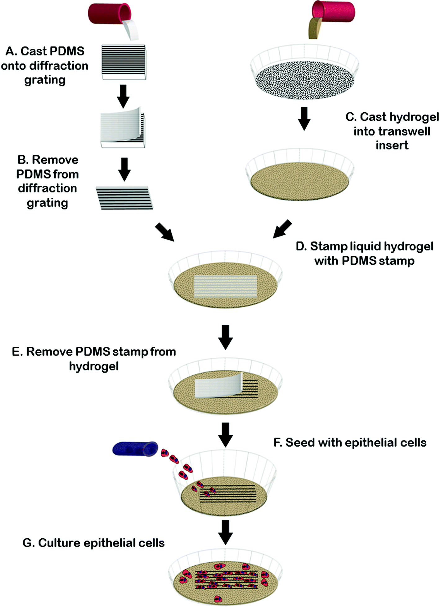 | ||
| Fig. 1 Generating microgrooved hydrogels using a PDMS stamp. Liquid Polydimethylsiloxane (PDMS) is cast onto diffraction grating and allowed to cure overnight (A). Once removed, microgrooved PDMS stamps are cut out using a biopsy punch (B). Stamps are then placed onto the surface of liquid gelatin (C and D). After gelation, stamps are removed (E) and the gels are crosslinked, washed and seeded with cells (F) and then cultured (G). | ||
While the diffraction grating method is sufficient for many applications where variations in geometry are not necessary, for experiments where varying groove depth was required we created stamps with controllable depth and geometry using silicon masters created using photolithography and deep etching using methods reported previously.29 Briefly, a Si-wafer was coated with S1811 positive resist. Photolithography was done using a chrome-glass photomask with regions containing 2 μm-pitch lines. Unexposed photoresist was removed by MF-321 developer. Dry etching was carried out using an inductively coupled plasma reactive ion etcher (Phantom II RIE/ICP System, Trion Technology, Tempe, AZ, USA). Etching times were adjusted to alter final groove depth and spacing. Prior to soft-lithography, patterned Si wafers (∼600 nm or ∼3.14 μm in depth, characterized by AFM) were washed with acetone and then silanized in a desiccator. Replica molding to obtain grooved PDMS substrate was achieved as described above.
To generate gel inserts, 5% (w/v) type A porcine gelatin (Sigma Aldrich, St. Louis MO, USA) was cast to a thickness of 1 mm in 4-well chamber slides (Millipore Ireland, Cork, Ireland) or in a transwell filter (Corning Incorporated, Tewksbury, MA, USA). The microgrooved PDMS stamp was then gently placed onto the surface of the liquid gelatin, microgroove side down, and the gelatin was allowed to gel for at least 6 hours at 4 °C. After gelation had occurred, the stamp was carefully removed and 0.1% (v/v) glutaraldehyde made from Type I, 25% stock (Sigma Aldrich, St. Louis, MO, USA) was added to the stamped (now solid) gelatin. The gelatin was then place placed back into 4 °C for at least 12 hours to allow crosslinking. After the gelatin was crosslinked, the gels were washed to remove any excess glutaraldehyde. Three washes of fetal bovine serum were followed by 7 washes with phosphate buffered saline (PBS) (Lonza, Walkersville, MD, USA), solution. All washes were five minutes in lengths. After the final PBS wash, the gelatin was covered with cell-appropriate media overnight at 4 °C. To generate flat gelatin insert controls we used the same protocol as for the microgrooved gels minus the step of imprinting of the microgrooved stamp in the gel surface.
Microgroove geometry characterization
The topography of the diffraction grating, PDMS replicas, and the imprinted gels was visualized using scanning electron microscopy. In preparation for microscopy, gelatin gels were crosslinked with 5% glutaraldehyde and then dehydrated in an ethanol dilution series overnight. A higher crosslinking concentration of glutaraldehyde was used to fix the structure of the grooves to avoid significant distortion during processing for SEM. After dehydration, the gels were frozen for two-minutes in liquid nitrogen and then freeze-dried (FreeZone® 2.5 Liter Freeze Dry System, Labconco, Kansas City, MO, USA) overnight. All samples were carbon coated (Edwards Coating System E306A, Tewksbury, MA, USA) and imaged using a Hitachi S-4500 (Hitachi High-Technologies Canada, Inc., Toronto, ON) at 1.5 kV.We also measured the dimensions of PDMS replicas of the diffraction gratings using atomic force microscopy (AFM). Images were collected in air at ambient temperature. A Digital Instruments Nanoscope IIIA Multimode AFM instrument was used in tapping mode with TESP diving board cantilevers with integral pyramidal tips. The cantilevers were operated at a drive frequency of ∼280 kHz. The samples were scanned at a rate of 1 Hz with a resolution of 512 × 512 pixels using a J-scanner with a nominal maximum scan window of 90 microns × 90 microns. All images were subjected to a 0-order flatten filter and a 2nd-order plane fit filter using the Nanoscope software (v. 5.12).
Gel imprinting grooves were also characterized using confocal microscopy. Gels were cast in 12-well transwells with 0.4 μm pore size as above in the generation of microgrooves. After crosslinking the gels the were washed with FBS and PBS. The gels were then kept in submerged culture for 72 hours and then stained with fluorescein isothiocyanate (FITC) at a concentration of 1:1000 for 30 minutes. The FITC solution was then vacuum aspirated and finally the gels were imaged with an Olympus IX-81 inverted confocal microscope.
Measurement of gel swelling properties
Gel swelling was assessed by first casting gels in a 12-well transwell with 0.4 μm pore size, allowing them to gel overnight at 4 °C, then crosslinking the gels with various concentrations of glutaraldehyde overnight at 4 °C. The gels were then dried on a kimwipe in a fumehood for 10 minutes to remove any excess moisture. The initial weigh step was done using an XS-210 weigh scale (Sartorius Canada Incorporated, Mississauga, Canada). After weighing, the gels were washed using our standard procedure of FBS and PBS (3 and 7 times respectively), then collagen coated overnight in tissue culture conditions (37 °C and 5% carbon dioxide). The gels were then media covered with DMEM/F12 in both apical and basal compartments for 24 hours. The apical compartment was then aspirated of all media to initiate 48 hours of ALI. The gels were then air dried in a fumehood on a kimwipe to remove excess moisture and then weighed. The equation used to calculate swelling was [(final − initial)/(initial)] × 100% = swelling.Gel insert seeding and ALI culture
For alignment experiments we seeded cells at confluent seeding densities (25000 cells cm−2) by pipetting the cells over the surface of the substrate and incubating overnight to allow for cell adhesion. Cultures were supplemented with fresh media and allowed to grow for 48 hours and then assayed for alignment.
For ALI studies, based on previous work,30 we expected confluent cultures to polarize and form cilia in ALI over a period of 2 days. To characterize cell behaviour on the inserts during apicobasal polarization we seeded 50000 cells cm−2 cells on 250 nm deep groove gelatin inserts and 500000 cells cm−2 on 2.4 micron deep groove inserts cast within a transwell. We also seeded 50000 cells cm−2 cells on transwell filter inserts with a flat gelatin or no gelatin insert (0.4 μm pore-size) for comparison. We observed that significantly greater numbers of cells were required to generate confluent sheets when cells were grown on deep grooves, possible due to less efficient adherence of the cells to the surface containing deep grooves during the seeding process. Cell sheet densities by 3 days were similar however on standard, collagen-coated transwells, and flat, or grooved samples (ESI Fig. 1‡). After seeding, cells were grown with medium present in the top and bottom compartments of the transwell filter until confluent. Once a confluent sheet was formed (approximately 24 h in both cases) we removed the media from the apical-compartment and replaced the basal-compartment with serum-free media to establish an ALI culture. Differentiation in ALI culture proceeded for 2 days after which the cells were fixed and prepared for staining.
Assessing cell alignment and apicobasal polarization
Cells were fixed with a 5% solution of paraformaldehyde for 10 minutes at room temperature and then permeabilized using a 0.1% Triton-100 (Sigma Aldrich) for 10 minutes. Cells were stained for nuclei with 4′,6-diamidino-2-phenylindole (DAPI) (1:300, Invitrogen, Eugene, Oregon, USA), and F-actin with rhodamine, or FITC conjugated phalloidin (1:300, Invitrogen) and mounted for fluorescence microscopy on an Olympus IX-81 inverted confocal microscope. An antibody against acetylated-tubulin (1:1000, Sigma Aldrich) was used to detect the formation of cilia on the apical surface of the polarized cells as a marker of apicobasal polarization.
Quantification of cellular alignment
We quantified the alignment of plasma membranes and cytoskeletal components, such as actin filaments, by tracing 20 separate phase contrast or fluorescent images by hand and analysing alignment using the angle measurement tool of ImageJ (NIH). Within each image, five cells in the four corners and one in the centre, were selected, traced and measured. To be measured, each cell must have had a complete border, that is to say, it was not touching the edges of the image. To specifically quantify the orientation of cytoskeletal components, actin within five cells was traced and measured in ImageJ using the trace tool. After the data was compiled, we used the graphing software Rozetta by Jacek Pazera, to create angular histograms which clearly demonstrate the quantified angular information.Quantification of ciliated cells
The mean number of primary ciliated cells per 2500 μm2 was quantified in control ALI and flat and grooved gelatin insert ALI conditions. Within each image, the number of cilia within a ciliated cell, indicated by localization of acetylated-tubulin with the nuclear marker DAPI was counted, and an average and the standard error of the mean were calculated.Statistics
To test for significant differences between two test groups, we first used an F-test to determine if equal variance could be assumed. If equal variance could be assumed, we used a pooled Student's t-test to identify significant differences between test groups. Otherwise, we used a non-pooled Student's t-test. For all tests, p-values of less than 0.05 were considered significant.Results
Insert fabrication and characterization
We have developed a method for generating microgrooved gelatin hydrogel inserts for in vitro culture. Firstly, we created microgrooved PDMS stamps by a simple replica molding technique using a diffraction grating or by molding from a microfabricated silicon masters. This allowed for the generation of a durable and flexible PDMS stamp that could be easily peeled off the gel surface after imprinting. The PDMS stamp was used to imprint microgrooves into gelatin hydrogels. Fig. 2 compares SEM images of the original diffraction grating (Fig. 2A) or silicon master, the grooved PDMS replica (Fig. 2B) and the resulting grooved gelatin inserts and clearly shows the replication of microgroove topography from the diffraction grating to the PDMS stamp to the gelatin hydrogel (Fig. 2C). Based on the manufacturer's specifications and AFM measurements, the diffraction grating had a pitch of 1μm and a depth of 186 nm. Consistent with the dimensions of the diffraction grating, AFM measurements of the PDMS replica indicated the grooves had a pitch of 1 μm and an average depth of 162 nm, (ESI Fig. 2‡). Furthermore measurements of groove pitch from SEM images of moulded PDMS stamp surfaces (Fig. 2B), were also consistent with AFM measurements. Measurements of Fig. 2C, which shows the microgrooves in a gelatin surface moulded from a microgrooved PDMS stamp, indicated that the gelatin grooves had a shorter pitch than expected. Similarly, with deep groove (3.14 μm deep) (Fig. 2E) gel samples had a shorter pitch than the PDMS replicas of our masters (Fig. 2D). This was not due to differences in gel swelling properties, which showed little variation at different concentration of GTA (ESI Fig. 3‡). We speculated therefore that this may be a result of the freeze-drying fixation procedure required for SEM preparation. We therefore quantified the percent macroscopic shrinkage of the gels during the freeze-drying process and found good agreement with the percent shrinkage in pitch at the macro and microscale. Specifically the average shrinkage in macroscopic gel dimensions was 2.3 ± 0.1 times versus 2.4 ± 0.2 times for shallow grooves and 1.1 ± 0.02 times and 1.1 ± 0.1 times for gels with deep grooves.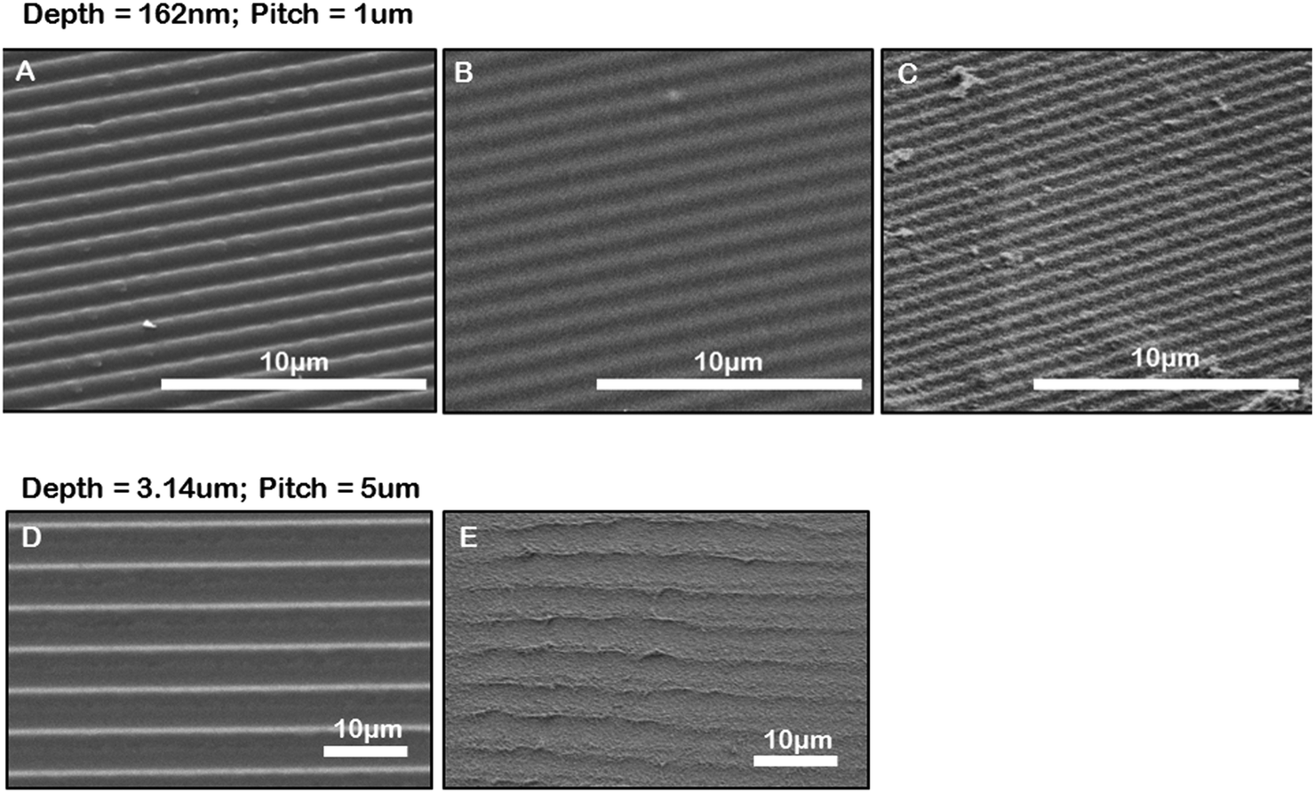 | ||
| Fig. 2 Characterization of microgrooved substrates. SEM image of a diffraction grating (A). SEM image of microgrooved PDMS replica molded from a diffraction grating (B). SEM image of a microgrooved gelatin hydrogel generated by imprinting the surface of the liquid gel with the PDMS stamp in B (C). SEM of PDMS replica molded from silicon master (D), (E) SEM of microgrooved gelatin containing deep grooves created by imprinting with PDMS stamp in (D). | ||
Gelatin, unlike collagen, is not stable at 37 °C and requires cross-linking to maintain gel stability under cell culture conditions. Glutaraldehyde (GTA) is a linear five-carbon dialdehyde that forms Schiff bases with free amine groups in the gelatin to produce crosslinks but is also toxic to cells at low concentrations.31 By minimizing the concentrations of GTA in the system we rationalized it would be easier to wash away any residual crosslinker that could have detrimental effects of cell viability. We therefore explored different GTA concentrations and crosslink times to identify conditions that would produce stable gels that were rigid enough to sustain the imprinting process (Table 1) with the least amount of crosslinking agent and in the shortest time to allow easy removal of any residual un-reacted GTA after the crosslinking step. We found we could generate repeatable and consistent microgroove topography in 5% gelatin hydrogels. For the best imprinting we found that allowing the gels to set overnight at 4 °C and then removing the PDMS stamp was critical. Gels were then fixed with 0.1% glutaraldehyde (GTA) for 12 to 18 hours. Using this cross-linking protocol we found that cell viability was unaffected if the gelatin inserts were washed three times with fetal bovine serum (FBS), an additional seven times with phosphate buffered saline solution (PBS), and then allowed to sit at 4 °C overnight in the cell specific media in which the cells were to be seeded the following day.
| Gelatin gel concentration (% w/w) | [GTA] (% v/v) | 0.05 | 0.1 | 0.25 | 0.5 |
|---|---|---|---|---|---|
| <1.5 | X | ||||
| 1.5 | X | X |

|

|
|
| 2 | X | X |

|

|
|
| 3 | X |

|

|

|
|
| 5 | X |

|

|

|
|
| 10 | X |

|

|

|
Epithelial cell alignment on gelatin microgrooved substrates
Confident that grooves were present in our gelatin hydrogel substrates and that our hydrogel was compatible with cell viability and growth, we next wanted to test the ability of the gelatin microgrooves to produce alignment of confluent sheets of epithelial cells specifically, since the first step in ALI culture is the generation of confluent sheets. Previous experiments reporting epithelial cell alignment in response to grooves have for the most part analyzed single cells and it is not clear if interactions with neighbouring cells limit the alignment possible with grooves in confluent sheets. Furthermore, gelatin is significantly more compliant than the substrate materials that have been tested in previous alignment studies such as PDMS and silicon therefore we also wanted to determine whether topographic cues in low compliance, soft materials could induce alignment of the airway epithelial cells, similar to what was observed for corneal epithelial cells recently. Fig. 3 shows brightfield micrographs of human airway BEAS2B epithelial cells grown on PDMS and gelatin microgrooves at confluent seeding densities. To quantify alignment in our images we hand traced cell membrane borders in ImageJ and measured the orientation angles. The resultant data was then compiled into Rozeta which generated corresponding angular histograms. These angular histograms are also shown in Fig. 3. As the images and histograms show, confluent cultures of BEAS2B cells oriented randomly on flat PDMS and gelatin, respectively (Fig. 3A and C) but aligned in the direction of the microgrooves on both PDMS and gelatin microgrooved substrates (Fig. 3B and D). Specifically 81% and 60% of the cells aligned within ±25° of the groove direction for on PDMS and gelatin grooves respectively. We also observed that on gelatin, cells were generally more rounded than on PDMS. We speculate that this is due to the more compliant mechanical properties of the 5% gelatin compared to PDMS (unpublished data). This may also explain why a lower percentage of cells align within ±25° of the groove direction on gelatin grooves as compared to PDMS grooves. We also characterized the impact of the gel microgrooves on cytoskeleton organization. As seen in Fig. 4, in confluent BEAS2B cells cultured on both microgrooved PDMS and microgrooved gelatin, long stalks of actin fibres extend the length of the cell and follow the direction of the microgrooves (Fig. 4B and D). Specifically, 76% and 59% of the actin fibres within cells aligned within ±25° of the groove direction for on PDMS and gelatin grooves respectively. An assessment of cells on grooves with the same geometry but two different depths (600 nm and 3.14 μm) indicated that, as expected, increasing groove depth leads to significantly less angular deviation from the groove direction and more robust alignment (ESI Fig. 4‡). Note: nuclei were quantified for alignment in this case as the deeper grooves distorted the imaging of actin cytoskeletal components. | ||
| Fig. 3 Cell alignment on microgrooved surfaces. Confluent BEAS2B cells align on microgrooved PDMS and gelatin substrates: Phase micrographs of confluent BEAS2B cells grown on flat PDMS (A), microgrooved PDMS (B), and flat (C) and microgrooved (D) gelatin substrates. Angular histograms corresponding to the above substrate condition quantify cell alignment on substrates where the red line indicates the direction of the grooves. Scale bars are 100 μm. | ||
 | ||
| Fig. 4 Cytoskeleton alignment on microgrooved surfaces. Confluent BEAS2B show F-actin alignment on microgrooved PDMS and gelatin substrates: Epifluorescence micrographs of phalloidin staining of F-actin in confluent BEAS2B cells grown on flat PDMS (A), microgrooved PDMS (B), and flat (C) and microgrooved (D) gelatin substrates. Angular histograms corresponding to the above substrate condition quantify cell alignment on substrates, where the red line indicates the direction of the grooves. Scale bars are 100 μm. | ||
We next sought to ascertain whether the ability of our grooves to align BEAS2B cells was applicable to other cell types or specific to airway epithelial cells. In particular we assessed alignment on our shallow grooves since for many applications, simple alignment with a groove above the threshold depth is sufficient and ease of fabrication is more important than the ability to vary groove geometry. Fig. 5 shows alignment of the murine mesenchymal cell line NIH 3T3, human retinal epithelial cell line ARPE19, and murine kidney epithelial cell line IMCD3. We included the 3T3 fibroblast cell line for comparison as fibroblasts are known to robustly respond to grooves.32–34 In all cases the grooves induced cell alignment on both grooved PDMS and gelatin but with varying efficiency depending on cell type. As expected NIH 3T3 fibroblasts showed alignment of the F-actin cytoskeleton in the direction of the grooves on microgrooved PDMS (Fig. 5A – white arrow) and microgrooved gelatin (Fig. 5C) compared to flat gelatin (Fig. 5B) with 63% and 64% of F-actin filaments within cells aligned within ±25° of the groove direction for on PDMS and gelatin grooves respectively. The human pigmented retinal epithelial cell line, ARPE19, also showed alignment of their F-actin cytoskeleton parallel to the microgrooves on PDMS (Fig. 5D) and gelatin microgrooves (Fig. 5F), with 83% and 72% of F-actin filaments within cells aligning within 25° of the grooves. The IMCD3 did not align the whole cell body with the grooves but did show F-actin cytoskeleton alignment parallel to the direction of the microgrooves on both PDMS (Fig. 5G) and gelatin (Fig. 5I) with 74% and 66% of F-actin filaments aligned within 25° of the groove direction for PDMS and gelatin respectively. This data suggested that even our shallow gel grooves that could be easily fabricated, were effective at aligning a number of cell types.
 | ||
| Fig. 5 F-actin cytoskeleton organization on flat versus grooved substrates for other cell types. Epifluorescence microscopy of F-actin stained (phalloidin) cells on microgrooved PDMS and gelatin substrates. NIH 3T3 fibroblasts grown on microgrooved PDMS (A), and flat (B) and microgrooved (C) gelatin substrates. Human pigmented retinal epithelial cells, ARPE19 grown on microgrooved PDMS (D), and flat (E) and microgrooved (F) gelatin substrates. Murine collecting duct epithelium, IMCD3 grown on microgrooved PDMS (G), and flat (H) and microgrooved (I) gelatin substrates. Angular histograms corresponding to the above substrate condition quantify cell alignment on substrates, where the red line indicates the direction of the grooves. Scale bars for A–F are 100 μm; and 50 μm for G–I. | ||
Epithelial cell polarization and cilia formation on gelatin inserts
We next set out to use our grooves to explore the relationship between cell alignment and apicobasal polarization. Specifically we wanted to determine if normal apicobasal polarization of the BEAS2B epithelial cells under ALI culture occurred on grooved gelatin inserts and how cell organization changed during this process. To assess apicobasal polarization we visualized and quantified the development of cilia, a marker of epithelial polarization, by staining for acetylated-alpha-tubulin. We assessed both the cilia number per unit area of epithelial sheet and the alignment of BEAS2B cells cultured on shallow grooves after apicobasal polarization. We found that there was no significant difference in the number of cilia formed on the gelatin inserts compared to standard transwells, but that, surprisingly, alignment of the cells in the direction of the grooves disappeared during the ALI culture (ESI Fig. 5‡). To determine if this resulted from groove degradation we repeated this experiment on deep grooves (Fig. 6) assessing cilia numbers and cell alignment at different time points in the apicobasal polarization process and compared this to cells kept in submerged culture. As expected, after 24 h + 48 h of submerged culture, BEAS2B on deep grooves did not undergo ciliogenesis (Fig. 6A) and nuclei remained aligned in the direction of the grooves (Fig. 6B). Similar to shallow grooves, cell polarization under ALI progressed normally on deep grooves and the number of cilia in cells increased over time in ALI culture and by 48 hours had reached levels of control cells on standard, collagen-control transwells (72 hours of ALI culture) (Fig. 6I). When we assessed cell alignment during this morphological polarization process we found that at 12 hours after initiation of ALI on deep grooves cell nuclei remained aligned in the direction of the grooves. Surprisingly, as observed on shallow grooves, at 24 and 48 hours after initiation of ALI nuclear alignment was progressively lost (Fig. 6E–H). Since cells remained aligned on grooves when ALI was not initiated and that we could clearly observe the deep grooves with fluorescence microscopy (ESI Fig. 7‡) we ruled out groove degradation. It is important to note that similar levels of ciliogenesis and similar cell densities (Fig. 6I and 6J) were found between collagen coated transwell controls and deep grooved gelatin after 48 hours of ALI (Fig. 6J). Similar results were obtained using ARPE19 and IMCD3 cell lines (Fig. 7), where alignment was lost after 24 h submerged culture plus 24 hours ALI culture.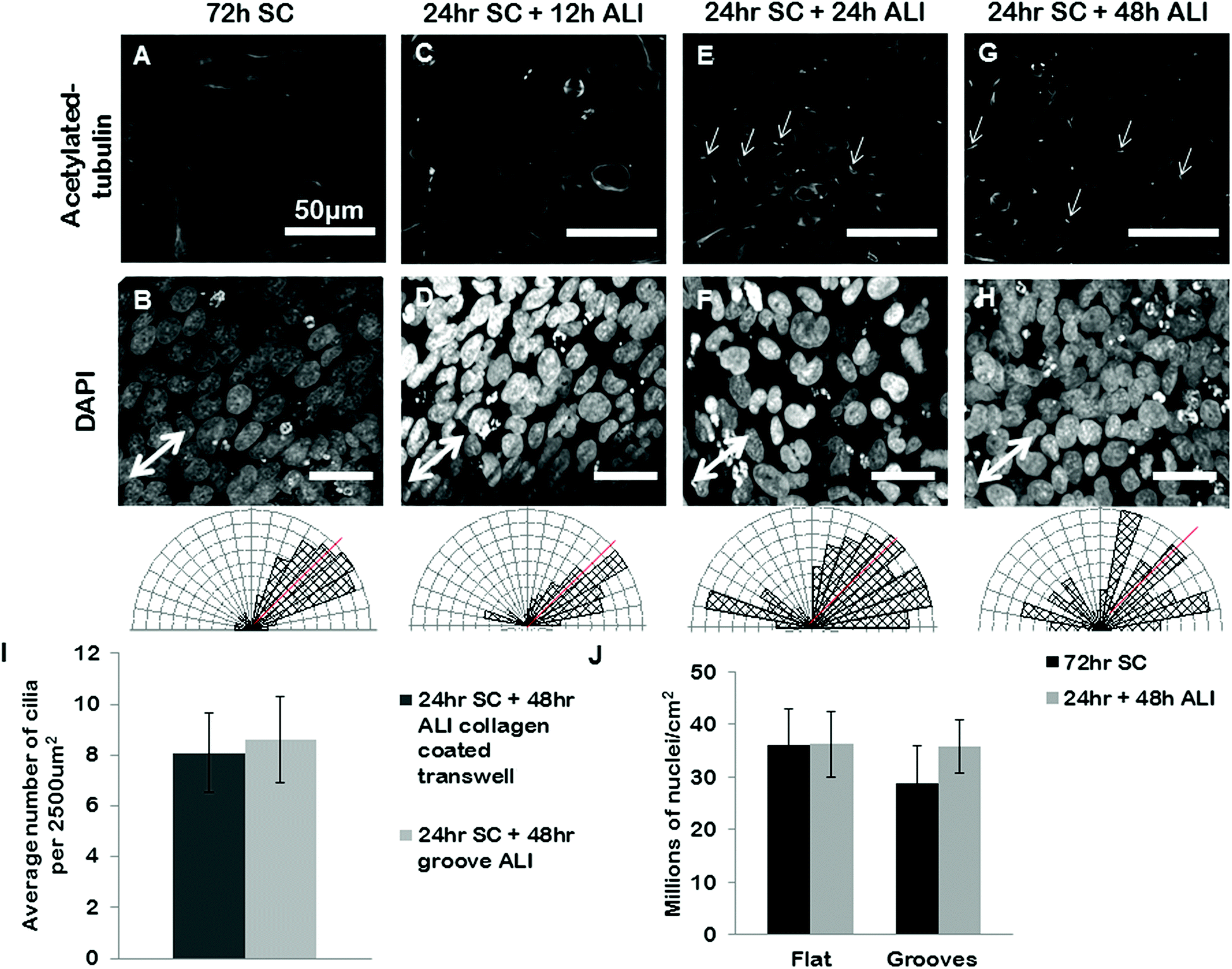 | ||
| Fig. 6 BEAS2B polarization and alignment in ALI culture on deep gelatin grooves. BEAS2B on gelatin microgrooves in transwell culture during submerged and ALI conditions. BEAS2B do not form cilia after 72 h of submerged culture (A) but do align (B) on gel grooves. At 12 h after initiating ALI cilia are not yet visible (C), and cells remain aligned in the direction of the microgrooves (D). At 24 hours (E and F) and 48 hours (G and H) of ALI culture well defined cilia are seen (E and G), however alignment in the direction of the grooves has been lost (F and H). Single headed arrows highlight exemplar primary cilia. Angular histograms corresponding to the above substrate condition quantify cell alignment on substrates, where the red line indicates the direction of the grooves. The number of cilia on grooved gelatin ALI culture is not significantly different than the cilia present on collagen coated standard ALI culture (I, and ESI Fig. 6‡). There appears to be no significant difference in cell density between flat and grooved culture during 72 hours submerged culture and 24 hours plus 48 hours ALI (J). Error bars represent standard error of the mean. Scale bars are 50 μm. | ||
 | ||
| Fig. 7 ARPE19 and IMCD3 on gelatin microgrooves in transwell culture during submerged and ALI conditions. ARPE19 align on microgrooves in 48 hours of submerged culture (SC) (A). 24 hours of SC + 12 hours of ALI culture, lead to less alignment (B), and loss of alignment by 24 hours of SC + 24 hours of ALI culture (C). IMCD3 align on microgrooves in 48 hours of submerged culture (SC) (D). 24 hours of SC + 12 hours of ALI culture, lead to less alignment (E), and loss of alignment by 24 hours of SC + 24 hours of ALI culture (F). Angular histograms corresponding to the above substrate condition quantify cell alignment on substrates, where the red line indicates the direction of the grooves. There appears to be no significant difference in the number of cells present in the sheet between flat and grooved culture during 48 hours SC and 24 hours SC plus 24 hours ALI in ARPE19 (G) and IMCD3 (H), respectively. Error bars represent standard error of the mean. Scale bars are 50 μm. | ||
Discussion
Epithelial tissue is both apicobasally and planar polarized. Apicobasal polarized epithelium can be created in vitro by using the transwell culture system; for airway epithelium this involves ALI culture. While ALI generates apicobasal polarized epithelium as seen through ciliogenesis, it does not instruct the morphological planar organization of tissues in vitro. A classic tissue-engineering method to organize and align cells is by culturing them on substrates containing topographic cues such as grooves. Most topography-based tools used for epithelial cells were: adapted from standard 2D tissue culture.14,35–38 These tools do not allow nutrient diffusion from the basal surface and are therefore ill-adapted for use in transwell culture; a necessary feature to promote apicobasal polarization and maturation of the epithelium. Here we successfully developed a method to culture epithelial cells on grooves while still allowing for ALI culture, to explore the impact of apicobasal polarization on morphologically planar organized cells.A key design feature of our insert was that it should allow nutrient diffusion to the basal side of the epithelial cells to promote apicobasal polarization. For this reason we chose to use a hydrogel material for the insert. Furthermore, hydrogels can be easily cast into transwell filters to be moulded, offering the opportunity to imprint the gel with topographic features to induce cell alignment. We chose to generate our inserts out of gelatin because this biopolymer is readily available, is relatively natural since it is generated from collagen, is biocompatible and often used as a coating for cell culture, and it can form relatively stiff hydrogels.39 We also rationalized that the selection of a gel with sufficient mechanical stiffness may be important to ensure the topographic features have enough strength to influence cell alignment. The key drawback with using gelatin is that it is unstable at 37 °C (standard cell culture temperature) unless it is crosslinked. Since the crosslinker glutaraldehyde is toxic to cells it was critical to thoroughly rinse out any uncrosslinked glutaraldehyde to ensure normal cell survival and growth on the inserts. Furthermore, in addition to standard rinses with PBS, we found that performing additional fetal bovine serum washes and incubating the insert overnight with serum medium of the cell type that was to be seeded, enhanced cell survival and growth on the inserts. We also assessed collagen for use as the insert material but did not find we could achieve robust imprinting in the grooves in the surface. Other synthetic biopolymers that are as rigid as gelatin but that do not require crosslinking to remain stable at 37 °C, such as polyethylene glycol,40 could be imprinted with topographic features using our method, if glutaraldehyde crosslinking is an undesirable step for a particular application.
Utilizing the microgroove pattern present in a diffraction grating, we developed a quick and simple technique to create a reusable stamp to imprint micro-topography into gelatin hydrogels. The diffraction gradient we used had grooves with a 1 μm pitch and 186 nm depth but other dimensions are available in a range of pitch and groove depths (edmundoptics.com), so our method is not limited to only these dimensions. Furthermore, if specific dimensions are desirable a silicon master can be created. We found that in a 5% gelatin gel, keeping the PDMS stamp in place for at least six hours while the gel underwent gelation at 4 °C was critical for pattern transfer. Pattern reproduction from the diffraction grating to the PDMS stamp and finally to gelatin hydrogel was clearly visible from our SEM images suggesting that our imprinting method is robust for generating microgrooved gels. The simplicity of our fabrication strategy will allow easy adoption of our method by other groups interested in manipulating epithelial organization under ALI conditions.
Our grooved inserts produced robust alignment of a number of epithelial cell types at the confluent densities required for ALI culture. The extent of morphological planar polarization induced by the grooves varied for different cell types: For most cell types tested the grooves produced both alignment of the whole cell membrane and the actin cytoskeleton (BEAS2B, 3T3 and ARPE-19 cells) but for some the groove produced only alignment of the actin cytoskeleton and not the whole cell (IMCD3). We speculate that differences between cell types arise from differences in the inherent mechanical properties of the cells due to differences in the rigidity of the plasma membrane, and tension within the cells. Understanding how the cellular response to a guidance cue depends on both the mechanical properties of materials presenting a guidance cue, and the mechanical properties of the cells being guiding is an interesting question for future study that our system could potentially be useful for probing. Furthermore, it would also be interesting to characterize the impact of these guidance cues on other structural features beyond just the cytoskeleton, such as the distribution of planar cell polarity signalling proteins, which become planar polarized in developing epithelium.41
Another key requirement of our insert material is that it is compatible with normal apicobasal polarization of the cells in ALI culture. We found that ALI culture on gelatin films cast within standard transwell inserts produced robust cilia formation with similar timing, location, and density to that observed in transwells with no inserts. This result is interesting because it suggests that the differing mechanical properties of the gelatin, and the slightly more round morphology of the cells on gelatin versus more rigid PDMS did not impact cilia formation. Exploring the impact of mechanical stiffness on epithelial cell polarization more extensively is an interesting area for future investigation.
Interestingly, assessing cell polarization using our grooved gel inserts revealed that while in submerged culture, airway, retinal and collecting duct epithelium responds as expected to grooved topography; in ALI culture however, the alignment cue appears to be overridden approximately 24 hours into ALI culture. We do not believe this was not due to geometry changes in the grooves during the ALI culture. Confocal analysis of groove geometry in fresh gels versus those after ALI culture also did not show any significant differences (ESI Fig. 7‡). Furthermore, cells aligned as expected when seeded on gel inserts that had been previously exposed to (i) 48 h ALI culture in the absence of cells or (ii) ALI culture in the presence of cells and subsequent removal of these cells before re-seeding with the cells of interest (ESI Fig. 8‡). Taken together these data suggest the grooves maintain their capacity to align cells under ALI conditions but that the cues provided by the grooves are overridden by another signal induced during apicobasal polarization. While the mechanism of this signal overriding is beyond the scope of this paper, we speculate that it could be caused by the structural changes inside the cell, such as changes in the actin cytoskeleton necessitated by apicobasal polarization.42,43 As apicobasal polarization proceeds, the planar-aligned cytoskeleton could be de-polymerized and re-polymerized into a contractile apical actomyosin belt-like complex resulting in loss of cell alignment with the groove. Our device offers a unique opportunity to further investigate this novel relationship between morphological planar polarization and apicobasal polarization.
Conclusion
By imprinting topographic cues into gelatin hydrogels we have shown that it is possible to control epithelial organization in epithelial cell lines in transwell ALI culture while concurrently allowing apicobasal polarization. Our method could be applied to probe a number of areas in epithelial biology. For example, the relationship between cell organization and alignment and the process of apicobasal polarization and how epithelial organization impacts cilia function and alignment. Furthermore, while we focused on device development using cell lines that form non-motile cilia, our device is potentially useful for probing the relationship between cell alignment and tissue organization and function in primary cells. Our system provides a novel model for studying epithelial biology and highlights the necessity of understanding the relationship between physical cues and tissue maturation in the pursuit of creating better organized tissue engineered constructs.Acknowledgements
The authors wish to thank Christopher Yip for assistance with AFM and Ahil Ganesh and Sutha Sathananthan for technical assistance. This work was funded by a Natural Sciences and Engineering Research Council of Canada (NSERC)/Canadian Institute of Health Research (CIHR) Collaborative Health Research Program (CHRP) grant to APM and TKW, and a Training Program in Regenerative Medicine/CIHR Scholarship to JPS. The authors have no conflict of interests to declare.References
- L. R. Johnson and J. H. Byrne, Essential medical physiology, Elsevier Academic Press, Amsterdam, Boston, 2003 Search PubMed.
- T. P. Fleming, Epithelial organization and development, Chapman & Hall, London, New York, 1992 Search PubMed.
- H. F. Lodish, Molecular cell biology, W.H. Freeman, New York, 2008 Search PubMed.
- S. Eaton, Curr. Opin. Cell Biol., 1997, 9, 860–866 CrossRef CAS.
- M. E. Werner, P. Hwang, F. Huisman, P. Taborek, C. C. Yu and B. J. Mitchell, J. Cell Biol., 2011, 195, 19–26 CrossRef CAS PubMed.
- M. R. Knowles and R. C. Boucher, J. Clin. Invest., 2002, 109, 571–577 CrossRef CAS.
- K. C. Dunn, A. E. Aotaki-Keen, F. R. Putkey and L. M. Hjelmeland, Exp. Eye Res., 1996, 62, 155–169 CrossRef CAS PubMed.
- Y. You, E. J. Richer, T. Huang and S. L. Brody, Am. J. Physiol. Lung Cell Mol. Physiol., 2002, 283, L1315–L1321 CAS.
- T. Koike, M. Yasuo, T. Shimane, H. Kobayashi, T. Nikaido and H. Kurita, Arch. Oral Biol., 2011, 56, 1170–1176 CrossRef PubMed.
- C. Nossol, A. K. Diesing, N. Walk, H. Faber-Zuschratter, R. Hartig, A. Post, J. Kluess, H. J. Rothkotter and S. Kahlert, Histochem. Cell Biol., 2011, 136, 103–115 CrossRef CAS PubMed.
- B. Button, M. Picher and R. C. Boucher, J. Physiol., 2007, 580, 577–592 CrossRef CAS PubMed.
- H. Matsui, S. H. Randell, S. W. Peretti, C. W. Davis and R. C. Boucher, J. Clin. Invest., 1998, 102, 1125–1131 CrossRef CAS PubMed.
- A. L. Oldenburg, R. K. Chhetri, D. B. Hill and B. Button, Biomed. Opt. Express, 2012, 3, 1978–1992 CrossRef PubMed.
- A. I. Teixeira, G. A. Abrams, P. J. Bertics, C. J. Murphy and P. F. Nealey, J. Cell Sci., 2003, 116, 1881–1892 CrossRef CAS PubMed.
- E. K. Yim, R. M. Reano, S. W. Pang, A. F. Yee, C. S. Chen and K. W. Leong, Biomaterials, 2005, 26, 5405–5413 CrossRef CAS PubMed.
- E. K. Yim, E. M. Darling, K. Kulangara, F. Guilak and K. W. Leong, Biomaterials, 2010, 31, 1299–1306 CrossRef CAS PubMed.
- M. J. Biggs, R. G. Richards, N. Gadegaard, C. D. Wilkinson and M. J. Dalby, J. Mater. Sci. Mater. Med., 2007, 18, 399–404 CrossRef CAS PubMed.
- D. H. Kim, P. Kim, K. Suh, S. Kyu Choi, S. Ho Lee and B. Kim, Conf. Proc. IEEE Eng. Med. Biol. Soc., 2005, 4, 4091–4094 Search PubMed.
- A. S. Curtis, N. Gadegaard, M. J. Dalby, M. O. Riehle, C. D. Wilkinson and G. Aitchison, IEEE Trans. Nanobioscience, 2004, 3, 61–65 CrossRef CAS.
- C. J. Bettinger, Z. Zhang, S. Gerecht, J. T. Borenstein and R. Langer, Adv. Mater., 2008, 20, 99–103 CrossRef CAS PubMed.
- S. Gerecht, C. J. Bettinger, Z. Zhang, J. T. Borenstein, G. Vunjak-Novakovic and R. Langer, Biomaterials, 2007, 28, 4068–4077 CrossRef CAS PubMed.
- K. A. Davis, K. A. Burke, P. T. Mather and J. H. Henderson, Biomaterials, 2011, 32, 2285–2293 CrossRef CAS PubMed.
- B. A. Dalton, X. F. Walboomers, M. Dziegielewski, M. D. Evans, S. Taylor, J. A. Jansen and J. G. Steele, J. Biomed. Mater. Res., 2001, 56, 195–207 CrossRef CAS.
- A. M. Rajnicek, L. E. Foubister and C. D. McCaig, Dev. Biol., 2007, 312, 448–460 CrossRef CAS PubMed.
- E. J. Tocce, V. K. Smirnov, D. S. Kibalov, S. J. Liliensiek, C. J. Murphy and P. F. Nealey, Biomaterials, 2010, 31, 4064–4072 CrossRef CAS PubMed.
- N. W. Karuri, P. F. Nealey, C. J. Murphy and R. M. Albrecht, Scanning, 2008, 30, 405–413 CrossRef CAS PubMed.
- S. A. Fraser, Y. H. Ting, K. S. Mallon, A. E. Wendt, C. J. Murphy and P. F. Nealey, J. Biomed. Mater. Res., Part A, 2008, 86, 725–735 CrossRef PubMed.
- B. Yanez-Soto, S. J. Liliensiek, C. J. Murphy and P. F. Nealey, J. Biomed. Mater. Res., Part A, 2013, 101A, 1184–1194 CrossRef CAS PubMed.
- C. Londono, M. J. Loureiro, B. Slater, P. B. Lucker, J. Soleas, S. Sathananthan, J. S. Aitchison, A. J. Kabla and A. P. McGuigan, Proc. Natl. Acad. Sci. U. S. A., 2014, 111, 1807–1812 CrossRef CAS PubMed.
- R. Jain, J. Pan, J. A. Driscoll, J. W. Wisner, T. Huang, S. P. Gunsten, Y. You and S. L. Brody, Am. J. Respir. Cell Mol. Biol., 2010, 43, 731–739 CrossRef CAS PubMed.
- A. P. McGuigan and M. V. Sefton, J. Tissue Eng. Regen. Med., 2007, 1, 136–145 CrossRef CAS PubMed.
- S. H. Yoon, Y. K. Kim, E. D. Han, Y. H. Seo, B. H. Kim and M. R. Mofrad, Lab Chip, 2012, 12, 2391–2402 RSC.
- D. H. Kim, K. Han, K. Gupta, K. W. Kwon, K. Y. Suh and A. Levchenko, Biomaterials, 2009, 30, 5433–5444 CrossRef CAS PubMed.
- W. A. Loesberg, J. te Riet, F. C. van Delft, P. Schon, C. G. Figdor, S. Speller, J. J. van Loon, X. F. Walboomers and J. A. Jansen, Biomaterials, 2007, 28, 3944–3951 CrossRef CAS PubMed.
- P. Clark, P. Connolly, A. S. Curtis, J. A. Dow and C. D. Wilkinson, Development, 1990, 108, 635–644 CAS.
- C. Y. Jin, B. S. Zhu, X. F. Wang, Q. H. Lu, W. T. Chen and X. J. Zhou, J. Mater. Sci. Mater. Med., 2008, 19, 2215–2222 CrossRef CAS PubMed.
- A. I. Teixeira, G. A. McKie, J. D. Foley, P. J. Bertics, P. F. Nealey and C. J. Murphy, Biomaterials, 2006, 27, 3945–3954 CrossRef CAS PubMed.
- N. W. Karuri, S. Liliensiek, A. I. Teixeira, G. Abrams, S. Campbell, P. F. Nealey and C. J. Murphy, J. Cell Sci., 2004, 117, 3153–3164 CrossRef CAS PubMed.
- A. Bigi, G. Cojazzi, S. Panzavolta, K. Rubini and N. Roveri, Biomaterials, 2001, 22, 763–768 CrossRef CAS.
- B. Yanez-Soto, S. J. Liliensiek, C. J. Murphy and P. F. Nealey, J. Biomed. Mater. Res., Part A, 2013, 101, 1184–1194 CrossRef CAS PubMed.
- E. K. Vladar, D. Antic and J. D. Axelrod, Cold Spring Harbor Perspect. Biol., 2009, 1, a002964 Search PubMed.
- S. Ohno and N. Takasu, J. Electron. Microsc., 1989, 38, 352–362 CAS.
- E. Rodriguez-Boulan and I. G. Macara, Nat. Rev. Mol. Cell Biol., 2014, 15, 225–242 CrossRef CAS PubMed.
Footnotes |
| † Dedicated to Michael Sefton on his 65th birthday for always being supportive of creativity, balance, and new ideas. |
| ‡ Electronic supplementary information (ESI) available. See DOI: 10.1039/c4bm00237g |
| This journal is © The Royal Society of Chemistry 2015 |