DOI:
10.1039/C4BM00234B
(Paper)
Biomater. Sci., 2015,
3, 134-143
In vitro study of directly bioprinted perfusable vasculature conduits
Received
6th July 2014
, Accepted 9th September 2014
First published on 15th September 2014
Abstract
The ability to create three dimensional (3D) thick tissues is still a major tissue engineering challenge. It requires the development of a suitable vascular supply for an efficient media exchange. An integrated vasculature network is particularly needed when building thick functional tissues and/or organs with high metabolic activities, such as the heart, liver and pancreas. In this work, human umbilical vein smooth muscle cells (HUVSMCs) were encapsulated in sodium alginate and printed in the form of vasculature conduits using a coaxial deposition system. Detailed investigations were performed to understand the dehydration, swelling and degradation characteristics of printed conduits. In addition, because perfusional, permeable and mechanical properties are unique characteristics of natural blood vessels, for printed conduits these properties were also explored in this work. The results show that cells encapsulated in conduits had good proliferation activities and that their viability increased during prolonged in vitro culture. Deposition of smooth muscle matrix and collagen was observed around the peripheral and luminal surface in long-term cultured cellular vascular conduit through histology studies.
1. Introduction
There has been a great success in engineering artificial organs such as skin,1,2 cartilage3 and bladders4,5 while they have simple morphology and architecture, low cell oxygen consumption rates, and no requirements for blood vessels. However, difficulties have been experienced with engineering thick, complex tissues or organs, such as heart, liver or kidney, primarily due to the lack of an efficient media exchange system.6
Fabrication of vascular tissues, with their complex cross-sectional structure, unique mechanical properties and hierarchical organization, presents a great challenge to tissue engineering.7,8 In the past three decades, several methodologies have been developed for the fabrication of vasculature conduits, including decellularized tissues,7,9,10 cell sheet conduits,11,12 biodegradable synthetic polymer-based constructs13,14 and natural biomaterial-based blood vessel constructs.15,16 Decellularized tissues offer several advantages, including their composition purely consisting of decellularized matrix (DCM) as well as their appealing mechanical properties. However, significant shrinkage is observed during decellularization17,18 due to rigorous decellularization process effecting the chemical composition, biological activity, and biomechanical properties of the remaining extra-cellular matrix (ECM). The cell sheet approach has appealing mechanical properties19 but poor structural organization.20 The synthetic polymer-based approach is the most well-studied approach. Although great success has been made in the fabrication of large-diameter vascular constructs, the synthetic-based method encounters issues in engineering small-diameter constructs with a diameter smaller than 5 mm.21 Small-diameter vascular constructs fabricated using synthetic materials have poor intermediate and long-term patency rates.22 Natural biomaterials have great biocompatibility and biodegradability, and provide an ideal substrate for cell attachment and proliferation.23 However, as an inherent weakness, the mechanical properties of natural biomaterials are limited. Vasculature conduits fabricated by available methods cannot generate an efficient media exchange system with perfusable networks to be incorporated into thick tissue fabrication because of their cumbersome fabrication procedures and nonprintable characteristics.
Bioprinting is a promising method for tissue fabrication providing high precision, high automation and high flexibility. 3D bioprinting is a layer-by-layer bioadditive approach, which involves cells during the fabrication process and allows the precise simultaneous 3D positioning of multiple cell types.24,25 In this regard, Norotte et al.15 used tissue spheroids and printed them sequentially in cylindrical form to build multicellular short stretches of vessels ranging from 0.9 to 2.5 mm in diameter. In that study, agarose cylinder was used as the temporary sacrifice material to create the lumen and support the entire structure; it was removed when the tissue maturation was achieved. Xu et al.16 proposed a platform-assisted inkjet printing system to fabricate zigzag or branched cellular tubes vertically through fusion of droplets with encapsulated fibroblast cells. Although bioprinting brings more flexibility to the fabrication of artificial vascular systems, incorporation of a small-diameter vascular system in thick tissue fabrication is still a challenge.
In this paper, human umbilical vein smooth muscle cells (HUVSMCs) were encapsulated and printed by a coaxial nozzle system. Perfusable vasculature conduits with controlled dimensions were printed. The proposed bioprinting system is capable of fabricating vasculature conduits of any length within a short fabrication time and can be easily incorporated into thick tissue fabrication and organ printing process. In this work, dehydration, swelling and degradation characteristics of vasculature conduits were investigated in detail; because, they offered important information about the degradation process of alginate conduits, which is critical for mechanical integrity as well as tissue regeneration. The perfusion and permeability capabilities, and unique mechanical properties are important characteristics of natural blood vessel. Thus, perfusion and permeability capabilities and mechanical properties of conduits made of different alginate concentrations were also explored in this paper. Cell viability was tested over a seven-day incubation period, and histology examinations were carried out to evaluate smooth muscle formation over a six-week culture period.
2. Experimental details
2.1. Materials
Prior to making a hydrogel solution, sodium alginate powder (Sigma Aldrich, U.K.) and calcium chloride (CaCl2) powder (Sigma Aldrich, U.K.) were treated with ultraviolet (UV) light for sterilization three times for a 30-minute cycle each time. UV-sterilized sodium alginate was dissolved in sterile deionized water to make 3%, 4% and 5% (w/v) solutions. Solutions were mixed with a magnetic stirrer (HANNA Instruments, U.S.A.) at room temperature until homogeneity was reached. Similarly, the crosslinking solution was prepared by dissolving UV-sterilized CaCl2 particles in ultra-purified sterile water (Invitrogen™ Life Technologies, U.S.A.) at 4%, 5% and 6% (w/v). With the exception of those in section 3.5, all alginate conduits used in this study were crosslinked with a 4% CaCl2 solution.
2.2. Cell preparation
Primary human umbilical vein smooth muscle cells (HUVSMCs) (Invitrogen™ Life Technologies, U.S.A.) were grown in 75 cm2 cell culture flasks in Medium 231 (Invitrogen™ Life Technologies, U.S.A.), supplemented with smooth muscle cell growth supplement (SMGS) (Invitrogen™ Life Technologies, U.S.A.), 10 U μl−1 penicillin, 10 μg ml−1 streptomycin, and 2.5 μg μl−1 fungizone (Invitrogen™ Life Technologies, U.S.A.). Cells were incubated at 37 °C in 98% humidity and 5% CO2. Cell culture medium was changed every 2 days. When the cultures reached 70% confluence, the cells were detached from the flasks using a 0.25% trypsin-EDTA solution (Invitrogen™ Life Technologies, U.S.A.), washed twice, re-plated for expansion or resuspended in 4% sodium alginate solution and gently mixed by a vortex mixer to get uniform distribution. Cells in passages 2–5 and at a density of 10 × 106 cells ml−1 were used in the experiments.
2.3. Fabrication of vasculature conduits
The fabrication system consisted of five parts: a single-arm robotic printer (EFD® Nordson, U.S.A.); a homemade coaxial nozzle unit; a syringe pump (New Era Pump System Inc., U.S.A.); a liquid dispenser (EFD® Nordson, U.S.A.); and a computer for robotic control (see Fig. 1A). A 14–25 gauge coaxial nozzle, fabricated with a 14 gauge outer needle (inner diameter = 540 μm and outer diameter = 1830 μm) and a 25 gauge inner needle (inner diameter = 250 μm and outer diameter = 520 μm), was used throughout all experiments. HUVSMCs loaded alginate and CaCl2 solutions were dispensed through the sheath and core sections of the coaxial nozzle, respectively (see Fig. 1B). When they contacted, crosslinking started immediately, forming conduits. The alginate dispensing pressure was set at 21 kPa, and the CaCl2 dispensing rate was set at 16 ml min−1. For fabrication of branched conduits, a window was opened at the wall of the stem conduit (larger) with a microsurgery scissor (Fisher Scientific, U.S.A.), which facilitated the insertion of the branch conduit (smaller). Upon insertion and alignment, a thin layer of alginate solution was sealed around the branching site.
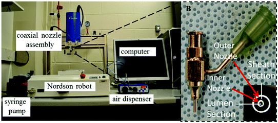 |
| | Fig. 1 Experimental setup: (A) the fabrication system, and (B) a homemade coaxial nozzle unit. | |
2.4. Scanning electron microscopy (SEM) imaging
After fabrication, conduits were soaked in a 4% CaCI2 solution for 12 hours to increase mechanical properties. First, conduits were randomly cut into short sections perpendicular to their longitudinal axis. Then, the cell media was completely rinsed off with phosphate buffered saline (PBS) (Sigma Aldrich, U.S.A.) followed by fixing cells in conduits at room temperature for two hours. Next, samples were rinsed three times using the same buffer used for the fixative (10 min per rinse) and post-fixed for one hour in 1% osmium tetroxide in the same buffer. Then, samples were dehydrated in graded ethanol solutions (from 25% to 100%). After dehydration, the samples were platinum coated to improve image quality. Images were taken using a scanning electron microscope (Hitachi S-4800).
2.5. Dehydration, swelling and degradation tests
Upon fabrication conduits were soaked in 4% CaCl2 solution for 30 minutes to ensure sufficient crosslinking. Thereafter, conduits were dehydrated at room temperature for four days. The dehydrated conduits were then soaked in a PBS (Sigma Aldrich, U.S.A.) solution for swelling and degradation studies. In these experiments, acellular conduits were used. The shrinkage rate by weight (SRW) and swelling ratio (SR) were calculated using the following equations:| |  | (1) |
| |  | (2) |
where Wo is the original conduit weight right after fabrication, Wi is the swollen conduit weight at the predetermined time point and Wd is the dehydrated conduit weight.
2.6. Dimensional characterization of vasculature conduits during dehydration, swelling and degradation
Conduit dimensions were measured using a light microscope (Motic®, BA310, U.S.A.) equipped with a digital camera. Conduit dimension measurements were conducted throughout the swelling and degradation tests. The four-hour point was selected as a measurement point because the swelling ratio of 5% conduits reached its maximum value at four hours. 5% alginate conduits were used in this experiment while their swelling ratio curve started decreasing earliest. The diameter shrinkage rate (DSR) was calculated as:| |  | (3) |
where Do is the original conduit diameter after fabrication, and Dd is the conduit diameter after dehydration.
2.7. Mechanical testing
After fabrication, conduits were crosslinked and soaked in CaCl2 solution for 24 hours. Soaking them in CaCl2 solution minimized the effect of residence time on samples.26 A Biotense Perfusion Bioreactor (ADMET, Inc., U.S.A.) was used to evaluate tensile strength characteristics. Each sample was a maximum of 30 mm long and mounted on rectangular mini sandpaper in order to prevent slippage during the test. Upon applying the mechanical load, conduits were ruptured in the middle or near edges. Displacement and load information data were recorded by a data acquisition system (MTestQuattro System, U.S.A.). The estimated burst pressure (BP) was calculated from ultimate tensile strength (UTS) measurements by rearranging the Laplace law for a pressurized thin-walled hollow cylinder,27 where BP is the estimated burst pressure (mmHg); T represents the wall thickness (μm) of conduits; and LD represents the unpressurized lumen diameter (μm) (see eqn (4)).| |  | (4) |
2.8. Perfusion and permeability testing
To test media perfusion and permeability capabilities of conduits, a customized perfusion system was developed. The media perfusion system consists of three parts: a cell culture media reservoir, a digital pump (Cole-Parmer, U.S.A.) and a custom-made perfusion chamber with a clear cover to prevent evaporation. Flexible needles inserted into conduits were selected depending on the lumen diameter of conduits. Surgery clips were used to fix the two ends of the conduits during perfusion to prevent leakage at the interface section. 3%, 4% and 5% alginate, and 4%, 5% and 6% CaCl2 solutions were used in perfusion experiments in order to explore the permeability of acellular conduits. Permeability was characterized using diffusion rate. Diffusion rate (μl per hour) was calculated by obtaining the volume of media diffused out from conduits to the perfusion chamber in an hour. For easy manipulation, conduits were soaked in CaCl2 solution for 24 hours. Directly after printing, conduits were soft and mechanically weak; this made the insertion of needles very challenging. This finding is also consistent with the literature, which pointed out that the elastic modulus of alginate increases as the gelation time increases, within 24 hours.26 In all perfusion experiments, the original length of conduits was fixed at 8 cm.
2.9. Cell viability
Following printing, cellular conduits were incubated at 37 °C in a 5% CO2 humid atmosphere for 1, 5 and 7 days. HUVSMCs viability in conduits was determined by using viability/cytotoxicity fluorescence test, calcein AM and ethidium homodimer-1. Conduits were perfused with 1.0 mM calcium acetoxymethylester (calcein AM) and 1.0 mM ethidium homodimer-2 (Invitrogen™ Life Technologies, U.S.A.) and incubated for 30 min at 37 °C. Calcein-AM labels healthy cells green and ethidium homodimer labels dead cells red. Following the 30 min exposure, cells were examined using a Leica fluorescence microscope (Leica Microsystems Inc., U.S.A.). Images were collected from three different locations randomly chosen from each sample. ImageJ (National Institutes of Health, U.S.A.) was used for automated counting of red- and green-stained HUVSMCs in each image, and percentages of viable cells were calculated.
2.10. Cell proliferation study
Following printing, constructs were placed in a 6-well tissue culture plate, and incubated at 37 °C in a 5% CO2 humid atmosphere for 1, 5 and 7 days. The proliferation of HUVSMCs was quantified by means of MTT [(3-(4,5-dimethylthiazol-2-yl)-2,5-diphenyltetrazolium-bromide)] assay (Invitrogen™ Life Technologies, U.S.A.), which directly measures the cellular metabolic activity through the biodegradation of tetrazolium salt by viable and active cells. Following each time point, conduits were cultured in the presence of a 1% (v/v) MTT solution (5 mg mL−1) for 4 h at 37 °C and 5% CO2. Following this culture period, 200 μL (in triplicate) of the supernatant was transferred from each well to a 96-well flat-bottom plate and the absorbance of the formazan dye was determined at 550 nm using a PowerWave X Microplate Reader (Bio-Tek, U.S.A.).
2.11. Tissue histology
In addition to the assessment of short-term cell viability, conduits were cultured for a prolonged time period, followed by a histology examination. After six weeks of in vitro culturing in smooth muscle cell differentiation media, fixed conduits were frozen and sectioned at 5 μm for histological examination. Verhoeff–Van Giesen staining was used to visualize collagen deposition, where collagen stains a red color. All the procedures were carried out per the manufacturers’ instructions. Sample slides were examined under an Olympus BX-61 brightfield fluorescence microscope (Olympus America, U.S.A.) at different magnifications.
2.12. Statistical analyses
The results shown in dimensional characterization experiments were an average of all 50 pieces of data. The statistical analysis was carried out using Minitab 17. The statistically significant difference was determined using the two-tailed student's t-test. Groups with a significance level of p < 0.05 were considered as significant. Standard error bars in all figures represent standard deviations. For experiments in section 3.2 and sections 3.4–3.6, sample size (n) is three.
3. Results and discussion
3.1. Fabrication of vasculature conduits
With fixed fabrication parameters, the average conduit and lumen diameter of 5% alginate conduits were 1449 ± 27 μm and 990 ± 16 μm, respectively. A microscope image of a conduit is shown in Fig. 2A. Uniform, smooth and well-defined walls can be observed in the figure. A long printed vasculature conduit with a length of approximately 80 cm was zigzag patterned and perfused with cell culture media (Fig. 2B). No occlusion or leakage was observed during the perfusion process. Fig. 2C is a two-week-cultured conduit. Long-term cultured conduits maintained their structural integrity with a well-identified lumen center and conduit wall. Fig. 2D shows the emulation of a branched vasculature by combining two conduits. Cell culture media pumped from the main stem can be successfully perfused out from both branch stems.
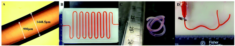 |
| | Fig. 2 Vasculature conduits: (A) light microscope image of conduits, (B) a long vasculature conduit printed in a zigzag pattern with perfused cell culture media, (C) a two-week-cultured vasculature conduit, and (D) a branched vasculature. | |
3.2. Dehydration, swelling and degradation tests
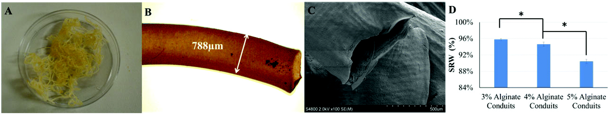
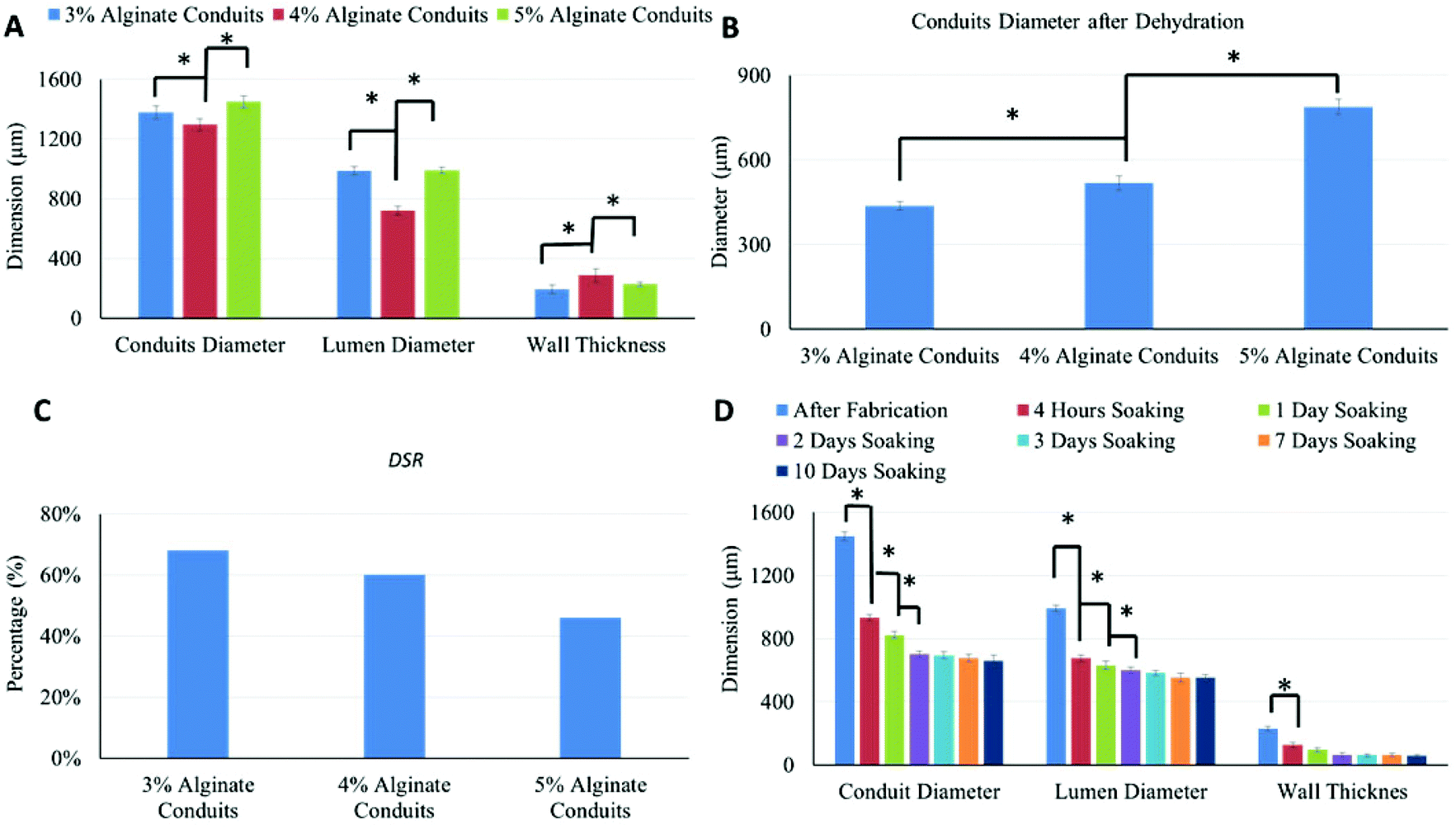
Alginate conduits with different concentrations were dehydrated at room temperature for four days. After dehydration, the majority of conduits remained in tubular shape. Fig. 3A shows a macroscopic photo of dehydrated 5% conduit. The conduit diameter shrank to 788 μm, which was 54.4% of the original conduit diameter (Fig. 3B and 3C). For all alginate concentration groups including the 3%, most of conduits maintained their tubular shape.
 |
| | Fig. 3 Alginate conduits in dehydration experiments: (A) Macroscopic image of dehydrated 5% alginate group, (B) dehydrated 5% alginate conduit under light microscope, (C) a SEM micrograph of a dehydrated 5% conduit still demonstrating tubular shape, (D) SRW of different alginate concentrations (the single asterisk * indicates significant difference between groups (p < 0.05)). | |
Fig. 3D is the SRW of conduits made of different alginate concentrations. During dehydration process, 3% alginate conduits lost more weight than others. The SRW decreased as alginate concentration increased. The SRW of 3%, 4% and 5% alginate conduit groups were 95.8%, 94.2% and 90.4%, respectively. Statistical significance was observed between groups.
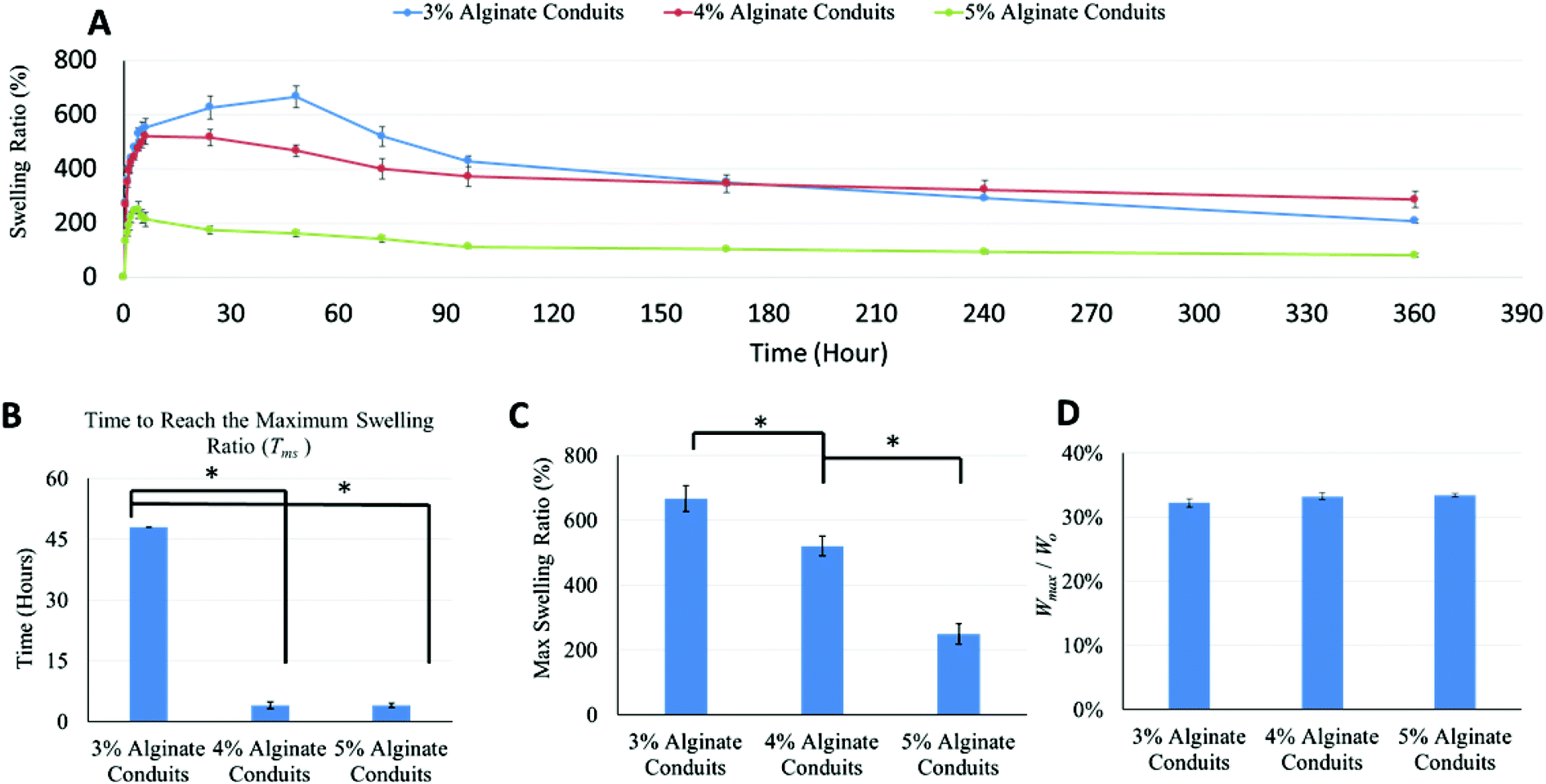
Swelling experiments were performed following the dehydration tests. Fig. 4A shows the swelling ratio curve over time for the 3%, 4% and 5% alginate conduit groups. For conduits made of different alginate concentrations, the swelling ratio curves depict obviously different trends. The initial slope of the swelling ratio curve of the 3% conduits was large, which indicates a high swelling rate. Since swelling and degradation experiments were performed at the same time, swelling ratio was also affected by dissociation of calcium alginate in PBS solution. Fig. 4B summarizes the time to reach the maximum swelling ratio (Tms). Tms decreased as alginate concentration increased. Fig. 4C shows the maximum swelling ratio. The maximum swelling ratio also decreased as alginate concentration increased, and the 3% group had the largest swelling capacity among all groups. Fig. 4D compared the liquid reabsorption capacities (Wmax/Wo) of the three groups, where Wmax is the conduits’ maximum swelling weight achievable. For conduits made of different alginate concentrations, Wmax/Wo remained similar, around 33%. This number indicated that dehydrated conduits from all groups “reabsorbed” liquid up to 33% of the original weight, despite their significantly different maximum swelling ratios. The Wmax/Wo value for the 3%, 4% and 5% alginate vasculatures were 32.2 ± 0.0062%, 33.3 ± 0.0054% and 33.4 ± 0.0037%, respectively. Compared to other groups, the 3% group had a smaller Wmax/Wo value; however it was not statistically significant.
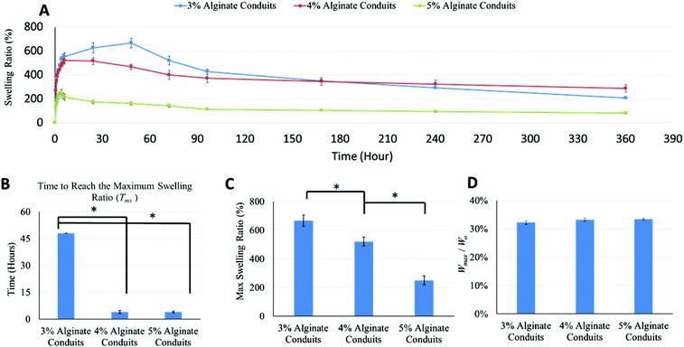 |
| | Fig. 4 Results of swelling experiments with different alginate concentrations: (A) swelling ratio curve, (B) time to reach the maximum swelling ratio (Tms), (C) maximum swelling ratio, (D) liquid reabsorption capability (Wmax/Wo) (the single asterisk (*) indicates significant difference between groups (p < 0.05)). | |
3.3. Dimensional characterization of vasculature conduits during dehydration, swelling and degradation
As shown in Fig. 5A, alginate concentration had significant influence on conduit dimensions. Conduits made of 4% alginate had the smallest conduit and lumen diameters, and the largest wall thickness. Small conduit and lumen diameter does not indicate a small wall thickness; rather, wall thickness can be affected by several factors such as crosslinking degree, nozzle configuration, dispensing flow rate of alginate and CaCI2 solutions, swelling, alginate shrinkage, conduit elasticity, etc. The conduit diameters after dehydration are shown in Fig. 5B. Dehydrated 3% alginate conduits had the smallest diameter, and the diameter of the dehydrated conduits increased as the alginate concentration increased. Fig. 5C shows the DSR of conduits made of different alginate concentrations; this was obtained using eqn (3). The DSR represents the shrinkage in uniaxial direction only. If we assume that the ionically crosslinked alginate structure is homogeneous, the shrinkage process should possess isotropic homogeneity, which means that shrinkage rates along all directions are the same. Three-dimensional shrinkage rates for the 3%, 4% and 5% conduits were 96.8%, 93.62% and 83.9%, respectively. The 3% group had the largest dehydration shrinkage rate and lost more weight and volume than the other groups. Both the DSR and SRW decreased as the alginate concentration increased. The values of DSR and SRW were similar and consistent. The shrinkage rate obtained in dehydration experiments could be an indicator for porosity of conduits (porosity is a measurement of void).28 A higher construct porosity is strongly desirable, as long as the construct can provide enough mechanical support for cells to grow on and make their own matrix. Ideal pore size for vascular grafts ranges from 10 μm to 45 μm,29 which is much higher than the porosity range in bioprinted conduits. Fig. 5D shows dimensional changes on 5% alginate conduits throughout the dehydration, swelling and degradation experiments. After four hours of soaking in PBS, although the conduits reached their maximum swelling ratio, the diameters of the swollen conduits were much smaller than the originally fabricated ones. Their diameters were only 64.4% of the originally fabricated ones.
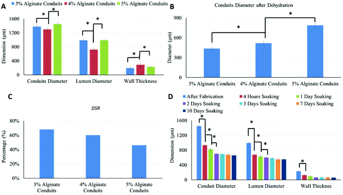 |
| | Fig. 5 Dimensional characterization during dehydration process: (A) dimensional variations in conduit groups, (B) conduit diameter after dehydration, (C) diameter shrinkage rate (DSR) of conduit groups, (D) dimensional changes of 5% alginate conduits over time (the single asterisk (*) indicates significant difference between groups (p < 0.05)). | |
Lumen diameter, conduit diameter and wall thickness all changed over time during the swelling and degradation processes, which was evidence of the occurrence of the swelling and degradation processes at the same time. The decrease in conduit diameter could be explained by presence of the degradation phenomenon. The decrease in lumen diameter, on the other hand, was mainly due to the swelling process. On the outer wall of conduits, the degradation process dominated the dimensional change. On the luminal wall of conduits, limited media could penetrate through pores and reach the luminal surface. The degradation rate was much slower than the swelling rate, and the swelling process dominated the dimensional change; thus, the lumen diameter of the conduits decreased over time. The conduits’ dimensional changes were significant during the first several days and became insignificant later on. This illustrates that both the swelling process and the degradation process slowed down over time. The slowdown of the swelling process occurred because the alginate conduits reached their maximum swelling capacity, whereas the degradation process slowed down for a much more complicated reason. The degradation of alginate hydrogel was due to the loss of Ca2+ ions. During the swelling and degradation experiments, PBS was not replenished. Over time, the Ca2+ ions in alginate and the PBS reached an equilibrium state, and thus the degradation process slowed down accordingly. Alginate has been used as biomaterial for vascular tissue graft applications and in general it has reasonable degradation rate in in vivo performance.30
3.4. Mechanical testing
The mechanical tests were performed to explore the mechanical properties of conduits. Table 1 demonstrates the tensile strength, elastic modulus, ultimate strain and calculated burst pressure of conduits with different alginate concentrations. It illustrates that the tensile strength of the 3% alginate conduits (110 ± 5.8 kPa) was lower than that of the 4% group (382 ± 19 kPa). A higher concentration of alginate resulted in a higher Young's modulus, from 105 ± 7.5 kPa for 3% conduits to 341 ± 23 kPa for 4% alginate conduits. The ultimate strain for the 3% alginate conduits was higher than the 4% groups, and the evaluated burst pressure increased as alginate concentration increased. The ultimate strain and evaluated burst pressure for 3% conduits were 0.82 ± 0.18 and 43.24 mmHg, and for 4% conduits were 0.69 ± 0.13 and 303.73 mmHg, respectively. A higher concentration of alginate resulted in significantly higher tensile strength, Young's modulus and burst pressure along with lower ultimate strain.
Table 1 Mechanical properties of vasculature conduits
| |
3% Alginate conduits |
4% Alginate conduits |
| Tensile strength (kPa) |
110 ± 5.8 |
382 ± 19 |
| Young's modulus (kPa) |
105 ± 7.5 |
341 ± 23 |
| Ultimate strain |
0.82 ± 0.18 |
0.69 ± 0.13 |
| Burst pressure (mmHg) |
43.24 |
303.73 |
The difference between the 3% and 4% groups’ estimated burst pressure is much more than that of tensile strength and Young's modulus. This is because burst pressure was estimated from the mechanical testing measurements and under the same fabrication parameters, the 3% group had greater lumen diameter as well as thinner conduit wall. Although 4% alginate conduits have much higher burst pressure compared with the 3% group, when it is compared with natural blood vessel, in which burst pressure is around 3561 mmHg,31 it is evident that further improvement is needed in future experiments. For example, connective tissue proteins such as collagen and elastin can be produced in nano-fiber form using nano-manufacturing techniques, i.e., electrospinning or electrohydrodynamic jetting, and reinforced into vasculature conduits to improve mechanical properties.
3.5. Perfusion and permeability testing
To determine the influence of cell culture media perfusion rate on the fabricated conduits and their diffusion capability, the flow rate of cell culture media was set at 1 ml min−1, 2 ml min−1 and 3 ml min−1, respectively. Fig. 6A demonstrates the influence of media perfusion rate on conduits’ dimensions. As shown in Fig. 6A, media perfusion rate had a significant influence on lumen diameter as well as conduit diameter. Both lumen diameter and conduit diameter increased as perfusion rate increased. As shown in Fig. 6B, perfusion time also had an influence on conduit dimensions. A 3 ml min−1 perfusion rate was chosen in this experiment because a larger perfusion rate is supposed to have more significant results. Cell culture media was perfused at 3 ml min−1 for one hour and three hours. Conduit diameter and lumen diameter were measured after perfusion. Results show that perfusion flow with a longer perfusion time had a greater influence on conduit dimension changes. Conduits that underwent a longer perfusion experiment had larger lumen and greater conduit diameter. When the conduit dimension changed, the diffusion rate changed accordingly. Fig. 6C plots conduit diffusion rate under different perfusion rates. With a higher perfusion rate, the diffusion rate became greater. Fig. 6D demonstrates that perfusion time also influenced diffusion rate of media in conduit. The diffusion rate increased as perfusion time increased, where diffusion rate shown in Fig. 6D is the average diffusion rate per hour. The permeated cell culture media through conduit walls was collected and measured per hour. The data in the 3 ml/min-2 h group included only the cell culture media diffused through the conduit in the second hour. Fig. 6E shows the diffusion rates in 3%, 4% and 5% alginate conduits, at a perfusion rate of 3 ml min−1. The 3% alginate conduits crosslinked with 4% CaCl2 were fragile due to their weak mechanical properties (as already demonstrated in Table 1) and thin wall thickness (see Fig. 5A). They were not suitable for the perfusion experiment, so their data were not included in Fig. 6E. Among all conduits crosslinked with the 6% CaCl2 groups, the 3% alginate conduits demonstrated the highest diffusion rate, which was 405 ± 11 μl per hour. For those conduits crosslinked by the same concentration of CaCl2, the diffusion rate decreased as alginate concentration increased, due to alginate hydrogel porosity decreased as alginate concentration increased. In addition, the diffusion rate increased as the crosslinker concentration decreased.
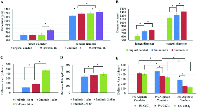 |
| | Fig. 6 Perfusion and permeability studies: (A) influence of perfusion rate on the 4% alginate conduit dimensions, (B) influence of perfusion time on the 4% alginate conduit dimensions, (C) influence of perfusion rate on the 4% alginate conduit diffusion rate, (D) influence of perfusion time on 4% alginate conduit diffusion rate, and (E) influence of material concentration, biomaterial and crosslinker on the diffusion rate (the single asterisk (*) indicates significant differences between groups (p < 0.05)). | |
The perfusion and permeability characterization experiments were carried out to understand the diffusion capability of media through conduits. As shown in the results, both lumen diameter and conduit diameter increased as perfusion rate increased. This phenomenon can be explained by axial stress. A higher perfusion rate corresponds to a larger axial stress inside the conduit. Because the alginate conduit is an elastic material, a higher axial stress would enlarge the conduit diameter further. The results also show that both perfusion rate and perfusion time had a significant influence on the diffusion rate. The main reason for the change in diffusion rate was the change in conduit dimensions. Conduits perfused with higher rates tended to have larger lumen diameter and thinner wall thickness, which increased the diffusion rate.
3.6. Cell viability and proliferation
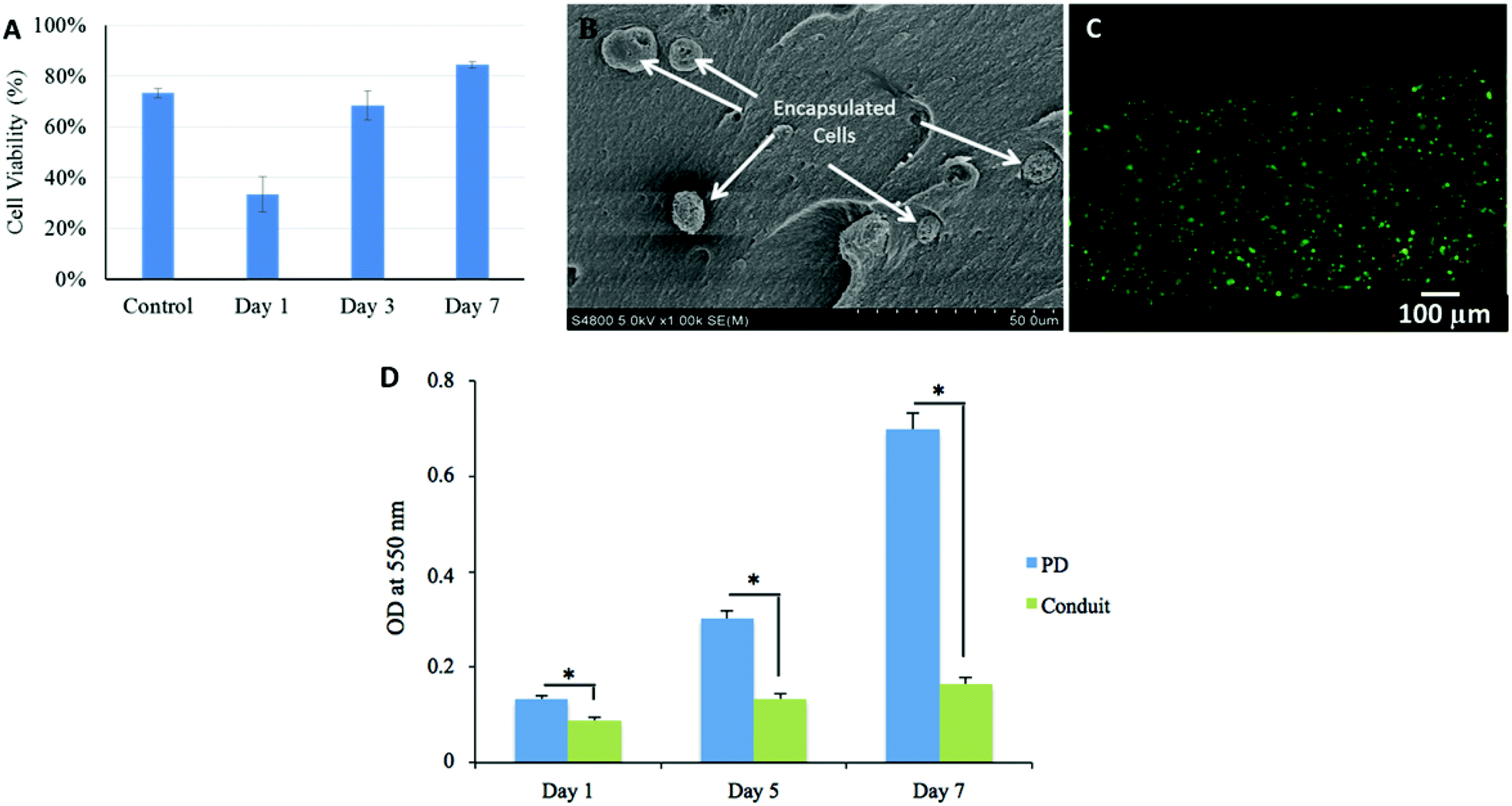
As demonstrated in Fig. 7A, initial cell viability was 73 ± 2% before printing. Cell viability was substantially affected during bioprinting and reduced to 33 ± 7%. During in vitro culture, cell viability rose to 68 ± 6% on day 3 and kept increasing until day 7; it increased to 84 ± 1%, which also exceeded the initial cell viability (73 ± 2%) before printing. Individual cells encapsulated in alginate matrix within the wall of the conduit were highlighted in a SEM image as presented in Fig. 7B. Cells were rounded while encapsulation in high concentration alginate network did not allow them to spread in short term culture. Fig. 7C shows a fluorescence microscopy image of a three-day-cultured conduit, in which the majority of cells were viable.
 |
| | Fig. 7 Cell viability testing: (A) cell viability percentage over one-week time period, (B) a SEM micrograph showing encapsulated cells, (C) a fluorescence image of a three-day-cultured conduit showing increasing cell viability, and (D) cell proliferation assessed by MTT assay (asterisk (*) indicates significant difference between groups (p < 0.05)). | |
Although the bioprinting system had an influence on cell viability, primarily due to the shear-stress-induced cell damage during the extrusion process, HUVSMCs encapsulated in conduits had good proliferation activities. During in vitro culture after bioprinting, cell viability kept increasing from the first day through day 7 and even exceeded the original cell viability. This may indicate that after fabrication, those injured cells not only were able to recover, but also were able to proliferate during incubation and support new tissue formation. Higher cell viability can be achieved by decreasing shear stress during the bioprinting process by using a larger coaxial nozzle or a lower extrusion pressure.32
An MTT assay was performed to evaluate the metabolic activity of the HUVSMCs encapsulated in conduits. As shown in Fig. 7D, cell viability was affected by the bioprinting process, where cell proliferation on free-cell suspension on Petri dish (PD) was greater than that of encapsulated ones; however, cells could grow and recover. The proliferative rate of the cells increased with culture period, which is in agreement with the cell viability results.
3.7. Tissue histology
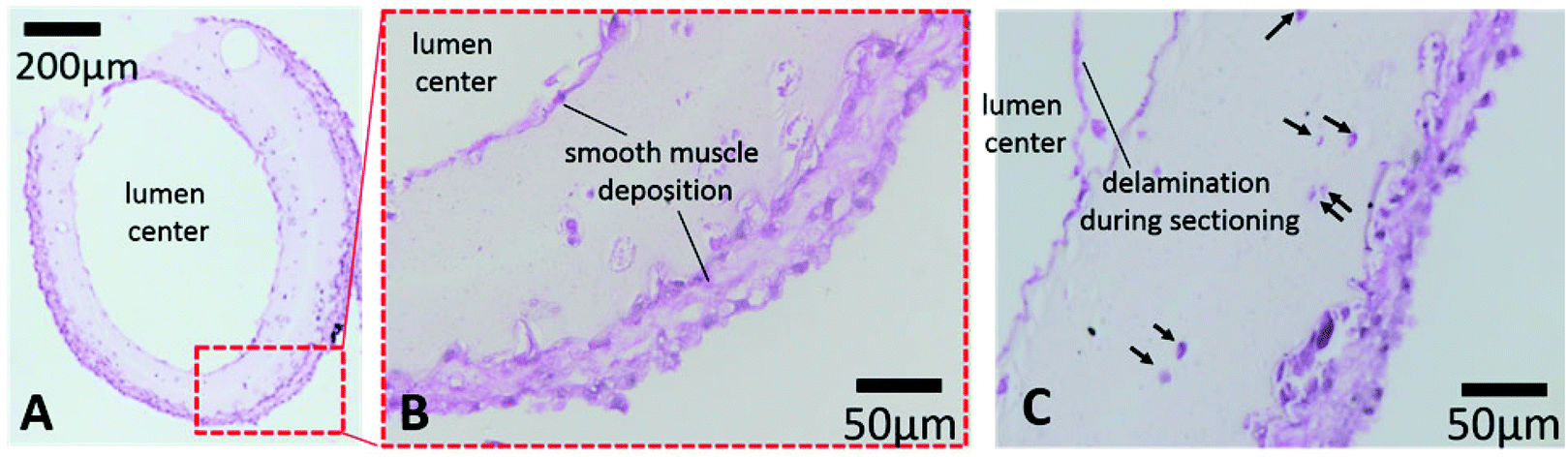
A histology study was performed to evaluate long-term cultured conduits for cell morphology and tissue-specific ECM formation. Printed conduits maintained their structural integrity with a well-defined lumen and conduit wall and ECM deposition in the inner and outer boundaries after six weeks in vitro culture (see Fig. 8A). Verhoeff–Van Gieson staining shows smooth muscle matrix deposition around cells and throughout the conduit wall (light pink color). Interestingly, thick cell sheets were formed on the peripheral and luminal surfaces with multiple layers of cells (see Fig. 8B and C), smooth muscle deposition stained with a purple-pink color. Cell sheets were closely attached on the conduit walls. While encapsulated cells were uniformly distributed in the conduit after bioprinting and do not attach on the surface of alginate, it is possible that cells migrated from their original lacunae towards the gradient of culture media to both the lumen side and the peripheral side, where there were greater oxygen and nutrient supplies. Upon migrating towards oxygen and growth factor gradients, cells started to grow and synthesized smooth muscle forming ECM close to the peripheral and luminal surfaces. This may suggest that continuous perfusion of culture media through the lumen might facilitate further cell migration and proliferation toward the lumen side in long-term-cultured conduits, potentially increasing smooth muscle formation. Some of encapsulated cells resided in their original lacunae and were largely intact, with a rounded stained nucleus and lighter stained cytoplasm (see Fig. 8C for longitudinal sectioning). For future attempts, uniformity of ECM distribution across the conduit can be obtained by increasing cell density and applying continuous perfusion in culture.
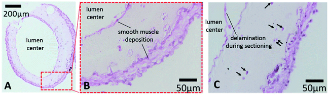 |
| | Fig. 8 Histology test for six-week-cultured conduits: (A) reasonable collagen deposition can be observed on long-term cultured vasculatures, and (B–C) thick cell sheets were formed on the conduit walls, where arrowheads show intact cells. | |
4. Conclusions
In this work, HUVSMCs encapsulated conduits were bioprinted in a practical way, which can be integrated into thick tissue fabrication or organ printing processes in the near future. The presented system offered several advantages, including that it had no post-fabrication procedure, and enabling direct bioprinting of complex media exchange networks. A functional branched network was also demonstrated. We investigated the dehydration, swelling and degradation characteristics of conduits along with their perfusability, mechanical strength and permeability capabilities because these properties are crucial for long-term function in perfusing and delivering media for thick tissues. Cell viability was affected by the bioprinting process; however, it was able to increase during incubation and later exceed original cell viability. In prolonged culture, cells within cellular conduits maintained their integrity and were able to carry out their functions. Reasonable extra-cellular matrix deposition was observed on both the peripheral and luminal surfaces. Conduits fabricated by a higher alginate concentration had lower cell viability, slower degradation process, less porosity and lower permeability capacity, as well as higher mechanical properties and bioprintability. In general, 4% works well for the application due to its bioprintability and mechanical and biological properties. For future work, we will develop vasculature conduits with reinforced native biomaterials, such as collagen or fibrin, and integrate vasculature networks with the rest of the tissue using the Multi-Arm Bioprinter developed in our recent work.33
Acknowledgements
This research has been supported by the National Institutes of Health (NIH) and the Institute for Clinical and Translational Science (ICTS) grant number ULIRR024979, and NSF CAREER award #1349716. The authors thank Dr Edward Sander and Aribet De Jesus from The University of Iowa's Biomedical Engineering Department for the mechanical testing experiments.
Notes and references
- M. Chen, M. Przyborowski and F. Berthiaume, Crit. Rev. Biomed. Eng., 2009, 37, 399–421 CrossRef PubMed.
- S. MacNeil, Mater. Today, 2008, 11, 26–35 CrossRef CAS.
- R. Tuli, W. J. Li and R. S. Tuancorresponding, Arthritis Res. Ther., 2003, 5, 235–238 CAS.
- H. Tian, S. Bharadwaj, Y. Liu, H. Ma, P. X. Ma, A. Atala and Y. Zhang, Biomaterials, 2010, 31, 870–877 CrossRef CAS PubMed.
- A. Atala, Br. Med. Bull., 2011, 97, 81–104 CrossRef PubMed.
- N. W. Choi, M. Cabodi, B. Held, J. P. Gleghorn, L. J. Bonassar and A. D. Stroock, Nat. Med., 2007, 6, 908–915 CrossRef CAS PubMed.
- W. S. Sheridan, G. P. Duffy and B. P. Murphy, J. Mech. Behav. Biomed. Mater., 2012, 8, 58–70 CrossRef CAS PubMed.
- J. P. Stegemann and R. M. Nerem, Ann. Biomed. Eng., 2003, 31, 391–402 CrossRef.
- S. L. Dahl, J. Koh, V. Prabhakar and L. E. Niklason, Cell Transplant., 2003, 12, 659–666 Search PubMed.
- A. Bader, T. Schilling, O. E. Teebken, G. Brandes, T. Herden, G. Steinhoff and A. Haverich, Eur. J. Cardio-Thorac. Surg., 1998, 14, 279–284 CrossRef CAS.
- P. B. Canham, E. A. Talman, H. M. Finlay and J. G. Dixon, Connect. Tissue Res., 1991, 26, 121–134 CrossRef CAS.
- N. L'Heureux, S. Pâquet, R. Labbé, L. Germain and F. A. Auger, FASEB J., 1998, 12, 47–56 Search PubMed.
- J. M. Caves, V. A. Kumar, A. W. Martinez, J. Kim, C. M. Ripberger, C. A. Haller and E. L. Chaikof, Biomaterials, 2010, 31, 7175–7182 CrossRef CAS PubMed.
- A. Salerno, S. Zeppetelli, E. Di Maio, S. Lannace and P. A. Netti, Biotechnol. Bioeng., 2011, 108, 963–976 CrossRef CAS PubMed.
- C. Norotte, F. S. Marga, L. E. Niklason and G. Forgacs, Biomaterials, 2009, 30, 5910–5917 CrossRef CAS PubMed.
- C. Xu, W. Chai, Y. Huang and R. R. Markwald, Biotechnol. Bioeng., 2012, 109, 3152–3160 CrossRef CAS PubMed.
- D. W. Courtman, C. A. Pereira, V. Kashef, D. McComb, J. M. Lee and G. J. Wilson, J. Biomed. Mater. Res., 1994, 28, 655–666 CrossRef CAS PubMed.
- H. M. Sung, C. S. Hsu, H. C. Chen, H. L. Hsu, Y. Chang, J. H. Lu and P. C. Yang, Artif. Organs, 1997, 21, 50–58 CrossRef CAS PubMed.
- N. L'Heureux, S. Pâquet, R. Labbé, L. Germain and F. A. Auger, FASEB J., 1998, 12, 47–56 Search PubMed.
- B. C. Isenberg, D. E. Backman, M. E. Kinahan, R. Jesudason, B. Suki, P. J. Stone, E. C. Davis and J. Y. Wong, J. Biomech., 2012, 45, 756–761 CrossRef PubMed.
- S. P. Hoerstrup, G. Zünd, R. Sodian, A. M. Schnell, J. Grünenfelder and M. I. Turina, Eur. J. Cardio-Thorac. Surg., 2001, 20, 164–169 CrossRef CAS.
- B. Tschoeke, T. C. Flanagan, S. Koch, M. S. Harwoko, T. Deichmann, V. Ellå, J. S. Sachweh, M. Kellomåki, T. Gries, T. Schmitz-Rode and S. Jockenhoevel, Tissue Eng., 2009, 15, 1909–1918 CrossRef CAS PubMed.
-
J. O. Hollinger, An Introduction to Biomaterial, CRC Press, Taylor & Francis Group, 2011 Search PubMed.
- D. Seliktar, D. Dikovsky and E. Napadensky, Isr. J. Chem., 2013, 53, 795–804 CAS.
- I. T. Ozbolat and Y. Yu, IEEE Trans. Biomed. Eng., 2013, 60, 691–699 CrossRef PubMed.
-
S. Khalil, Phd. Thesis, Drexel University, 2006.
- R. Gauvin, M. Guillemette, T. Galbraith, J. M. Bourget, D. Larouche, H. Marcoux, D. Aubé, C. Hayward, F. A. Auger and L. Germain, Tissue Eng., 2011, 17, 2049–2059 CrossRef PubMed.
- F. Zhang, J. Chang, J. Lu, K. Lin and C. Ning, Acta Biomater., 2007, 3, 896–904 CrossRef CAS PubMed.
- S. Sarkar, C. Hillery, A. Seifalian and G. Hamilton, J. Vasc. Surg., 2006, 44, 846852 CrossRef PubMed.
-
D. L. Wise, D. J. Trantolo, K. Lewandrowski, J. Gresser and M. V. Cattaneo, Biomaterials Engineering and Devices: Human Applications: Volume 1: Fundamentals and Vascular and Carrier Applications, Springer-Verlag, 2010 Search PubMed.
- G. Konig, T. N. McAllister, N. Dusserre, S. A. Garrido, C. Iyican, A. Marini, A. Fiorillo, H. Avila, W. Wystrychowski, K. Zagalski, M. Maruszewski, A. L. Jones, L. Cierpka, L. M. de la Fuente and N. L'Heureux, Biomaterials, 2009, 30, 1542–1550 CrossRef CAS PubMed.
- Y. Yu, Y. Zhang, J. Martin and I. T. Ozbolat, J. Biomech. Eng., 2013, 135(9), 091011 CrossRef PubMed.
- I. T. Ozbolat, H. Chen and Y. Yu, Rob. Comput.-Integr. Manuf., 2014, 30, 295–304 CrossRef PubMed.
|
| This journal is © The Royal Society of Chemistry 2015 |
Click here to see how this site uses Cookies. View our privacy policy here.