 Open Access Article
Creative Commons Attribution 3.0 Unported Licence
4-Methylresorcinol based bent-core liquid crystals with azobenzene wings – a new class of compounds with dark conglomerate phases†
Mohamed
Alaasar
*ab,
Marko
Prehm
a,
Marcel
Brautzsch
a and
Carsten
Tschierske
*a
aInstitute of Chemistry, Martin Luther University Halle-Wittenberg, Kurt Mothes Str. 2, D-06120 Halle (Saale), Germany. E-mail: carsten.tschierske@chemie.uni-halle.de
bDepartment of Chemistry, Faculty of Science, Cairo University, Giza, Egypt. E-mail: malaasar@sci.cu.edu.eg
First published on 9th June 2014
Abstract
Stochastic achiral symmetry breaking in soft matter systems, leading to conglomerates of macroscopically chiral domains (so-called dark conglomerate = DC phases) is of contemporary interest from a fundamental scientific point of view as well as for numerous potential applications in chirality sensing and non-centrosymmetric materials. Herein we report the synthesis and investigation of first azobenzene containing bent-core mesogens derived from 4-methylresorcinol forming DC phases with a new structure, distinct from the known fluid sponge-like distorted smectic phases as well as from the helical nano-filament phases (HNF phases, B4 phases). The effects of chain length and other structural modifications on achiral symmetry breaking were investigated. Homologues with relatively short alkyl chains form achiral intercalated lamellar LC phases (B6 phases), but on increasing the chains, these are replaced by the chiral and optically isotropic DC phases. Compounds with the longest alkyl chains form low birefringent crystalline conglomerates which represent less distorted versions of the optically isotropic DC-phases. Introducing additional peripheral substituents at both outer rings removes the DC phases. The DC phases were also removed and replaced by modulated smectic phases if the azo groups were replaced by ester units, showing that azo groups favour DC phase formation with new nanostructures, distinct from the previously known types.
1. Introduction
Since the discovery of polar order and chirality in the liquid crystalline (LC) phases of compounds with a bent aromatic core (bent-core liquid crystals = BCLCs)1 this field has become a thrust area of liquid crystal research by providing a significant impact on the general understanding of molecular self-assembly in soft condensed matter.2,3 Moreover, these materials are also of significant interest for numerous practical applications, as ferroelectrica, flexoelectrica and pyroelectrica,4 for command surfaces and sensors,5 non linear optical applications6 and in fast switching electrooptical devices.7 A great fraction of contemporary interest is focussed on the so-called dark conglomerate phases (DC phases).8–18 The common feature of these DC phases is the absence of birefringence due to a local distortion of long range periodicity and the inherent phase chirality indicated by stochastic achiral symmetry breaking, leading to conglomerates of macroscopically chiral domains. These DC phases can be subdivided into the liquid crystalline smectic phases (sponge phases)8–15 and the soft crystalline helical nanofilament phases (HNF phases, also assigned as B4 phases).16–19 In the sponge type DC phases, layers without in-plane order are strongly deformed in a nonregular way, so that uniformly oriented regions become smaller than the wavelength of light. In contrast, the HNF phases are composed of helical filaments with a crystalline packing of the aromatic cores in twisted ribbons, here only the chains are in a disordered state. As there is no preferred direction for these filaments these phases appear optically isotropic. The major tool for distinguishing these two structures is XRD, where the wide angle scattering around d = 0.45 nm is completely diffuse for the LC sponge phases whereas for the soft crystalline HNF phases a series of relatively sharp scattering could be found in this region.16a,20,21 The reduced symmetry as a result of the tilted organization of molecules in polar layers (layer chirality),3,16 the collective segregation of chiral molecular conformations and a combination of both are considered as possible origins of the remarkable chirality and mirror symmetry breaking in these soft matter structures.2a,b,8,17a,22 HNF phases might become interesting materials for a number of applications, such as organic semiconductors for thin-film transistors and solar cells,23 as thin-film polarizers,22 as nonlinear optical materials24 as well as for the detection and amplification of chirality.25Interestingly, almost all of the known BCLCs with HNF phases incorporate the hydrolytically unstable benzylideneaniline (Schiff base) moiety with the exception of only very few recent examples.26–28 This calls for new materials with DC phases, showing enhanced chemical stability and providing new phase sequences involving the HNF phases. A broader variety of different molecular structures could also lead to an improved understanding of the molecular structural factors governing the formation of distinct subtypes of DC phases, thus providing rules for the directed design of such materials.
BCLCs incorporating azo (–N![[double bond, length as m-dash]](https://www.rsc.org/images/entities/char_e001.gif) N–) linkages represent versatile materials due to their photochromic effects in addition to high birefringence and high polarizability, leading to significant nonlinear optical activity.6,29,30 The cis–trans isomerisation of the azo linkage in the presence of UV light could be used, for example, in high-density data storage systems, for sensors, photonic switches and molecular logic gates.31 Though a variety of azobenzene based BCLCs with interesting properties have been reported,29,32–34 until recently no such BCLCs with DC phases have been available; only bent dimesogens combining two rod-like azobenzene units via an odd-numbered alkylene spacer were reported.27 We have found that iodine28 or bromine34a substitution in 4-position at the bent central resorcinol unit of azobenzene based BCLCs leads to a new type of DC-phases (Scheme 1).28 Hence, it appears that the size of the halogens is of importance. Bulky halogen atoms like bromine (cv = 0.33 nm3)35 or iodine (cv = 0.45 nm3),35 seem to be favourable for formation of DC phases, whereas no DC phases were found for BCLC with hydrogen32e or smaller halogens in the same position (see Scheme 1; F: cv = 0.13 nm3; Cl: cv = 0.27 nm3).34,35 Hence, the question arose if azobenzene BCLCs with other bulky groups at the bent core, having a size comparable to iodine/bromine, could also lead to azobenzene based BCLCs showing DC phases. The methyl group has a size (cv = 0.32 nm3)35 comparable to bromine but it is almost non-polar in contrast to the C-halogen bonds which introduce a significant dipole moment.
N–) linkages represent versatile materials due to their photochromic effects in addition to high birefringence and high polarizability, leading to significant nonlinear optical activity.6,29,30 The cis–trans isomerisation of the azo linkage in the presence of UV light could be used, for example, in high-density data storage systems, for sensors, photonic switches and molecular logic gates.31 Though a variety of azobenzene based BCLCs with interesting properties have been reported,29,32–34 until recently no such BCLCs with DC phases have been available; only bent dimesogens combining two rod-like azobenzene units via an odd-numbered alkylene spacer were reported.27 We have found that iodine28 or bromine34a substitution in 4-position at the bent central resorcinol unit of azobenzene based BCLCs leads to a new type of DC-phases (Scheme 1).28 Hence, it appears that the size of the halogens is of importance. Bulky halogen atoms like bromine (cv = 0.33 nm3)35 or iodine (cv = 0.45 nm3),35 seem to be favourable for formation of DC phases, whereas no DC phases were found for BCLC with hydrogen32e or smaller halogens in the same position (see Scheme 1; F: cv = 0.13 nm3; Cl: cv = 0.27 nm3).34,35 Hence, the question arose if azobenzene BCLCs with other bulky groups at the bent core, having a size comparable to iodine/bromine, could also lead to azobenzene based BCLCs showing DC phases. The methyl group has a size (cv = 0.32 nm3)35 comparable to bromine but it is almost non-polar in contrast to the C-halogen bonds which introduce a significant dipole moment.
 | ||
| Scheme 1 LC phases found for 4-halogenoresorcinol based bent-core mesogens with azobenzene wings (abbreviations: Cr = crystalline solid, USmC = undulated smectic phase; N = nematic phase, B6 = intercalated smectic phase formed by ribbons with only short range register; DC = dark conglomerate phase; phases in brackets were observed only for one homologue in a small temperature range).28,34a | ||
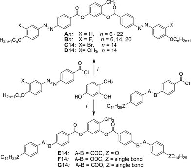
Here we report a series of new BCLCs derived from 4-methylresorcinol36,37 possessing two azobenzene side arms (An, see Scheme 2). These compounds show B6 phases if the terminal chains are short and a new type of dark conglomerate phases if the chains are sufficiently long. Besides these isotropic DC phases also a birefringent crystalline conglomerate was observed for a long chain compound. The formation of this phase depends on the applied cooling rates and the transition between the isotropic and birefringent types of conglomerate phases was studied. In addition, the effect of lateral groups X (see Scheme 2, X = F, Br, CH3) at the outer rings of these BCLCs (compounds Bn, C14 and D14, respectively) has been investigated. The phase behaviour of these new compounds is compared with related compounds incorporating terephthalate or benzoate based wing groups instead of the azobenzenes, either reported in the literature36 or synthesized herein (E14, F14 and G14 see Section 3.6).
2. Experimental
Synthesis
The synthesis of the target BCLCs A/n–D/n with azobenzene wings was performed as shown in Scheme 2 by acylation of 4-methylresorcinol with 4-(4-n-alkoxyphenylazo)benzoyl chlorides (X = H) or their 3-substituted derivatives with X = F, CH3, Br (see Scheme S1†). For the synthesis of compounds E/14–G/14 appropriately substituted benzoyl chlorides (see Scheme S2†) were used for the acylation reactions.37 Details of the synthesis of the intermediates and final compounds as well as analytical data are reported in the ESI.†Methods
The mesophase behaviour and transition temperatures were measured using a Mettler FP-82 HT hot stage and a control unit in conjunction with a Nikon Optiphot-2 polarizing microscope. The associated enthalpies were obtained from DSC-thermograms which were recorded on a Perkin-Elmer DSC-7, the heating and cooling rate was 10 K min−1. Electro-optical switching characteristics were examined in 6 μm polyimide coated ITO cells (EHC Japan) using the triangular-wave method. XRD patterns were recorded with a 2D detector (Vantec-500, Bruker). Ni filtered and pin hole collimated CuKα radiation was used. The exposure time was 15 min and the sample to detector distance was 8.95 and 26.7 cm for small angle and wide angle scattering experiments, respectively. Samples were aligned by slow cooling (rate: 1–0.1 K min−1) of a small droplet of the compound on a glass plate and takes place at the sample–air interface. The samples were held on a temperature-controlled heating stage.DFT computation was carried out with the Gaussian 09 package.38 Geometry optimization was performed with the B3LYP functional and the LAN L2 DZ basis set. The solvation model was IEFPCM with solvent chlorobenzene.
3. Results and discussion
3.1 Overview over the LC phases formed by compounds An–Dn
The thermal behaviour of all synthesized compounds was studied by polarizing optical microscopy (POM) and differential scanning calorimetry (DSC). The transition temperatures (°C), the associated phase transition enthalpies (kJ mol−1) and the phase sequences of compounds An, Bn, C14 and D14 are given in Table 1. All compounds are thermally stable as confirmed by the reproducibility of thermograms in several heating and cooling cycles. Related compounds E/14–G/14 with phenylbenzoate wing groups instead of the azobenzenes, synthesized for comparison purposes, are described and discussed in Section 3.6.| Comp. | n | X | Heating | Cooling |
|---|---|---|---|---|
| a Before measurement the compounds were melted and heated to 150 °C to remove traces of enclosed solvent, afterwards they were cooled with 10 K min−1 to room temperature; the phase transition temperatures (peak temperatures) were taken from the following heating and cooling scans at 10 K min−1, if not otherwise specified; abbreviations: SmC = synclinic tilted birefringent smectic phase; SmCaPA = anticlinic tilted antiferroelectric SmC phase; Iso = isotropic liquid; Cr[*] = crystalline phase composed of a conglomerate of chiral domains, for other explanations, see Scheme 1. b Obtained on heating after previous cooling to 75 °C with 10 K min−1. c Obtained on heating after previous cooling to 80 °C with 20 K min−1. d Total enthalpy for both transitions. e Obtained on heating after previous cooling to 80 °C with 2 K min−1. f The actual phase sequence strongly depending on conditions, see DSC traces in Fig. 2b; transition enthalpy value could not be determined for the B6-DC transition (see Section 3.3). g Cooling with 2 K min−1. h Partial crystallization. | ||||
| A6 | 6 | H | Cr 124 [41.0] B6 131 [11.9] Iso | Iso 129 [12.3] B6 |
| A8 | 8 | H | Cr 111 [35.9] Iso | Iso 96 [11.1] B6 62 [9.1] Cr |
| A9 | 9 | H | Cr 110 [37.4] Iso DC 100 [22.7] Isob | Iso 87 [9.4] B6 67 [16.5] Crf Iso 87 [9.4] B6 ∼ 85 DC [≥9.1] 67 Crf |
| A10 | 10 | H | Cr 107 [37.4] Iso DC 100 [25.5] Isoc | Iso 87 [24.1] DC |
| A12 | 12 | H | Cr 109 [38.1] Iso DC 102 [27.3] Isob | Iso 87 [26.8] DC |
| A14 | 14 | H | DC 101 [31.4] Iso | Iso 88 [33.9] DC |
| A16 | 16 | H | DC 102 [40.8] Iso | Iso 90 [43.9] DC |
| A18 | 18 | H | DC 103 [49.6] Iso | Iso 93 [51.7] DC |
| A20 | 20 | H | Cr[*] 99 DC 104 [68.0]d Iso DC 104 [56.7] Isoe | Iso 92 [70.8] Cr[*] Iso 95 [59.0] DCg |
| A22 | 22 | H | Cr[*] 105 [73.2] Iso | Iso 96 [76.5] Cr[*] |
| B6 | 6 | F | Cr 112 [41.3] Iso | Iso 88 [8.6] SmCaPA 67 [10.5] Crh |
| B14 | 14 | F | Cr 90 [32.9] SmCaPA 95 [12.8] Iso | Iso 90 [15.2] SmCaPA 74 [39.8] Cr |
| B20 | 20 | F | Cr 95 [93.0] Iso | Iso 92 [16.0] SmCaPA 82 [77.7] Cr |
| C14 | 14 | Br | Cr 78 [77.2] Iso | Iso 30 [53.2] Cr |
| D14 | 14 | CH3 | Cr 79 [47.9] Iso | Iso 33 [0.9] SmC < 20 Cr |
3.2 B6-type intercalated smectic phases of the short chain compounds A6 and A8
Compounds An without lateral substituents at the outer rings of the bent-core structure exhibit two different types of mesophases. On heating the shortest homologue (A6, with n = 6) a transition from the crystalline state to a focal-conic fan-shaped texture is observed at T = 124 °C (Fig. 1a). The dark extinctions are parallel to a polarizer and an analyzer, indicating an average orthogonal or anticlinic tilted smectic phase. No homeotropic alignment with pseudoisotropic areas or with birefringent Schlieren texture, as typical for SmA or SmC phases, respectively, could be achieved by shearing the sample. Instead, a fine fan-texture is immediately reformed after releasing shear stress (see Fig. S2†), as typical for intercalated smectic phases of bent-core mesogens, assigned as B6 phases.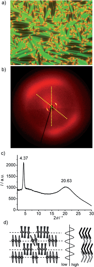 | ||
| Fig. 1 Compound A6. (a) Texture (crossed polarizers) as observed for the B6 phase at T = 120 °C (on cooling, textures observed after applying shear stress are shown in Fig. S2†); (b) XRD pattern of an aligned sample of the B6-phase at 80 °C; (c) 2θ-scan over this pattern and (d) the proposed model of the molecular organization in the B6 phase, left: view along the bending direction, right: side view perpendicular to the molecular bending plane (in this direction the ribbons are quasi infinite) and the assumed electron density modulation profile in the middle.41 | ||
The XRD pattern (Fig. 1b and c) shows only one sharp peak in the small angle region corresponding to a d-value of 2.0 nm (T = 80 °C), which is smaller than half of the molecular length (Lmol) in a conformation with a 120° bent aromatic unit and the alkyl chains in the most stretched all-trans conformation. For compound A6Lmol is between 4.3 and 4.5 nm, depending on the assumed conformation shown in Fig. S1.† This confirms the intercalated B6-type smectic phase deduced from optical investigations. According to the present understanding, this is a frustrated smectic phase with layers broken into ribbons and adopting a staggered organization with only short range periodicity between the ribbons (see Fig. 1d); the layer frustration takes place in the direction perpendicular to the molecular bending plane (Fig. 1d).39,40
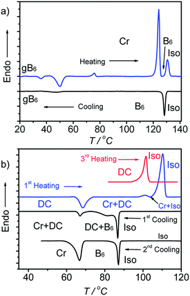
The wide angle scattering is diffuse and has a maximum at 0.43 nm, in line with the LC state of this phase. For an aligned sample this scattering is split into four maxima indicating the presence of a tilt of about 26° (Fig. 1b and S12†). This tilt could arise either from a tilt of the molecular bending planes, or alternatively, from the inherently tilted orientation of the individual rod-like wings of the bent-core mesogens, similar to anticlinic SmC phases.41 The latter would be in line with recent microbeam XRD results obtained for B6 phases of Schiff base compounds.39a In this case the orientation of the molecules would be on average orthogonal and the splitting is related to the angle of the molecular bent of 128° which is in good agreement with the geometry provided by the molecular structure. This would also be in line with the optical textures which have the extinction brushes strictly parallel to the polarizers (see Fig. 1a). However, the measured d value is a bit shorter than half the molecular length (2d/Lmol ∼ 0.9) which in this case must be attributed to partial intercalation and conformational disorder of the alkyl chains. On cooling A6 from the isotropic state the B6 phase appears at T = 129 °C and remains on cooling down to room temperature without visible crystallization of the sample (for DSC traces, see Fig. 2a), but the sample becomes glass-like solid without any change of the texture at ∼40 °C. This might indicate a transition to a glassy state of the B6 phase or an isomorphous crystallization. As no clear DSC peak (only a small hump between 40 and 50 °C, see Fig. 2a) was observed in the cooling traces and crystallization is observed >35 °C on heating, a glassy B6 phase (gB6) appears more likely.
In electrooptical investigations using a triangular wave voltage no current peak could be observed in the whole temperature range of this mesophase up to a voltage of 200 Vpp in a 6 μm ITO cell. These observations, together with the relatively high transition enthalpy value of ΔH = 12.3 kJ mol−1 for the Iso–LC transition at T = 129 °C are in line with the suggested B6 phase. With increasing chain length (n = 8 and 9) the B6 phase is retained but the Iso–B6 transition temperature decreases to 96 °C for A8 and to 87 °C for A9, and the B6 phase becomes monotropic (metastable) for these two compounds.
3.3 Competition between B6 and DC phases in A9
On cooling the B6 phase of A9 a highly viscous, almost solid-like optically isotropic mesophase starts to grow at T = 85 °C (Fig. 3a and b). Uncrossing the polarizers by a small angle leads to the appearance of dark and bright domains. Uncrossing the polarizer in the opposite direction reverses the dark and bright domains (Fig. 3c and d). Rotating the sample between crossed polarizers does not lead to any change and this indicates that the distinct regions represent chiral domains with opposite handedness, as typical for dark conglomerate phases (DC phases). The distribution of the areas of domains with opposite chirality is on average 1![[thin space (1/6-em)]](https://www.rsc.org/images/entities/char_2009.gif) :
:![[thin space (1/6-em)]](https://www.rsc.org/images/entities/char_2009.gif) 1. The formation of the DC phase is slow and on further cooling the remaining B6 phase rapidly crystallizes with formation of a birefringent crystalline phase (see Fig. 3b) at T = 67 °C, while the DC phase only very slowly crystallizes. On heating the areas of the DC phase go to the isotropic liquid state at T = 100 °C, while the birefringent crystalline regions of the sample melt to a clear liquid at T = 110 °C. This indicates that the B6-phase, formed first, is thermodynamically unstable and upon annealing is replaced by the isotropic DC phase and a birefringent crystalline phase. Formation of the DC phase is in competition with fast crystallization, but the DC phase once formed crystallizes only slowly (see Fig. S3†). However, after slow cooling (2 K min−1) to ∼70 °C, followed by immediate heating, a uniform DC phase can be obtained (see 3rd heating curve in Fig. 2b).42
1. The formation of the DC phase is slow and on further cooling the remaining B6 phase rapidly crystallizes with formation of a birefringent crystalline phase (see Fig. 3b) at T = 67 °C, while the DC phase only very slowly crystallizes. On heating the areas of the DC phase go to the isotropic liquid state at T = 100 °C, while the birefringent crystalline regions of the sample melt to a clear liquid at T = 110 °C. This indicates that the B6-phase, formed first, is thermodynamically unstable and upon annealing is replaced by the isotropic DC phase and a birefringent crystalline phase. Formation of the DC phase is in competition with fast crystallization, but the DC phase once formed crystallizes only slowly (see Fig. S3†). However, after slow cooling (2 K min−1) to ∼70 °C, followed by immediate heating, a uniform DC phase can be obtained (see 3rd heating curve in Fig. 2b).42
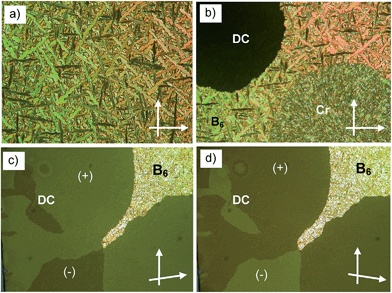 | ||
| Fig. 3 Optical micrographs observed for A9 between crossed polarizers: (a) B6 phase at T = 86 °C; (b) growth of the DC phase and the birefringent crystalline phase from the B6 phase; (c) DC phase as grown from B6 (T = 83 °C, different region) after rotating one polarizer by 10° from the crossed position in the anticlockwise direction and (d) in the clockwise direction, showing the chiral domains (on a larger field of view the stochastically distributed chiral domains occupy equal areas); the texture related to (c), (d), but between 90° crossed polarizers is shown in Fig. S3b†; additional textures are shown in Fig. S3a, c and d.† | ||
3.4 DC phases of the long chain compounds A10–A22
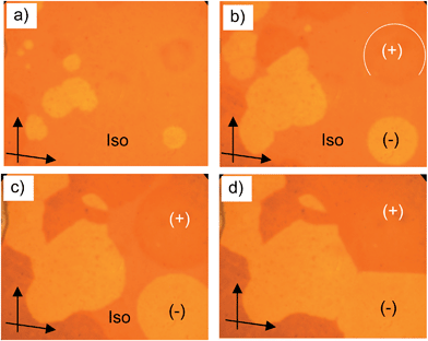 | ||
| Fig. 4 a–d) Growth of the circular chiral domains of the DC phase of A10 upon cooling from the isotropic liquid state at T = 87 °C as observed between slightly uncrossed polarizers (see arrows); the textures of the DC phase of A14 are shown in Fig. S4.† | ||
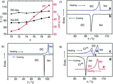
The melting of the DC phases (DC–Iso-transition) takes place around 100–104 °C and the crystallization of the DC phase (Iso–DC transition) is found between 87 and 95 °C for all compounds A10–A20 and both transition temperatures increase slightly with rising alkyl chain length (see Table 1 and Fig. 5a). Hence, there is a supercooling of this phase transition by about 10 K (peak temperatures at scanning rates of 10 K min−1). The formation of the DC phases is associated with relatively high transition enthalpies, ranging between ΔH ∼ 24 and 59 kJ mol−1 (measured in cooling scans), strongly rising with growing alkyl chain length from A10 to A20 (see Table 1 and Fig. 5a).
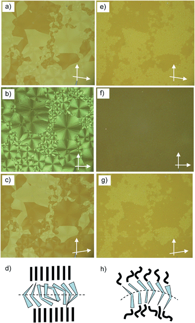
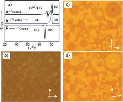
Compounds A10 and A12 easily crystallize on cooling or on reheating, but the DC phases of compounds with longer chains (n = 14–20) do not crystallize, once the DC phase is formed, as shown in Fig. 5b for compound A18 as an example (for additional DSC curves, see Fig. S7 and S8). In the case of the long chain compound A20 a different behaviour is observed which is discussed here in some more detail. For this compound there is a strong effect of the cooling rate on the phase sequence and the phase structure (see Fig. 5c and d). On cooling from the isotropic liquid phase with a low rate of ≤2 K min−1 (Fig. 5c, curve b) the DC phase is formed at T = 95 °C and it does not crystallize on further cooling, and on heating only a single peak is observed at T = 104 °C (Fig. 5c, curve a), similar to compounds A14–A18 (Fig. 5b). The transition enthalpy is ∼57 kJ mol−1 on heating and ∼59 kJ mol−1 on cooling. However, on cooling with a faster rate of ≥5 K min−1 (Fig. 5d, curve d) a crystalline phase with a weakly birefringent spherulitic texture (see Fig. 6b) is formed at T = 92 °C and the transition enthalpy is now significantly larger, around ∼71 kJ mol−1 on cooling.44 The spherulitic texture (Fig. 6b) is similar to those found for columnar or (modulated) smectic LC phases, however, this phase is solid-like and does not flow on applying shear forces, and therefore, this is a crystalline phase.
Interestingly, also this crystalline phase is chiral and composed of domains with opposite handedness, i.e. dark and bright domains become visible if the polarizers are slightly uncrossed (see Fig. 6a and c), hence, this birefringent conglomerate phase is assigned as Cr[*]. Each of the spherulites appears to have uniform chirality, so it seems that the chirality is determined by each nucleus and is preserved through the growth process.45 On further cooling the Cr[*] phase is retained and does not change down to room temperature, but on heating to T = 99 °C it transforms into the DC phase. At this transition the spherulitic texture becomes uniformly isotropic and the chirality as well as the sign of chirality in the distinct domains is retained (see Fig. 6e–g). This temperature corresponds to the position of the exotherm II in the heating curve c in Fig. 5d. The unusual shape of the DSC heating curve c is characterized by a significant tailing which rises up to a local maximum I, before it abruptly goes through an exothem II, and finally the peak maximum III is reached. This kind of DCS curve is always found for the heating curves after cooling the sample with rates ≥5 K min−1, independent of the used heating rates (see Fig. S9†). The endothermic tailing I, starting at T ∼ 85 °C, is interpreted as a result of a chain melting process which leads to a softening of the Cr[*] phase. This obviously allows a denser packing (crystallization) of other molecular parts, giving rise to the exotherm II in the heating curve. At this temperature the Cr[*] phase transforms into the DC phase, i.e. this transition is accompanied by a layer deformation which leads to the formation of the optically isotropic DC phase at T = 99 °C. On further heating this DC phase melts into the isotropic liquid at the endothermic peak III at T = 104 °C. Once formed (either on cooling the preformed DC phase or on slow cooling from the isotropic liquid sate), the DC phase is stable and it is retained down to room temperature; only a single peak at T = 104 °C is observed on heating (curve e in Fig. 5d). Even after storage at room temperature for more than 8 weeks the same transition temperatures and enthalpies were obtained. The persistence of the DC phases might be the result of the freezing of disordered alkyl chain segments into an immobilized, probably a glassy state, which, once formed, inhibits the transformation into the chiral Cr[*] phase or any other crystalline phase.
Compound A22 with the longest chains is a crystalline solid with a melting point at T = 105 °C. No formation of a DC phase could be detected at any cooling rate. Also in this case the crystalline phase formed on cooling consists of a conglomerate of chiral crystals (see Fig. S5†), though the chiral domains cannot be observed with the same clarity as for A20, because the birefringence is higher and no uniform texture is obtained. In the following focus is on the DC phases of compounds A10–A20.
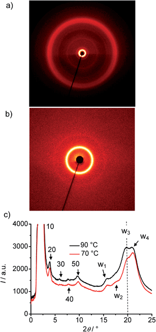 | ||
| Fig. 7 XRD pattern of the DC phase of compound A14 at T = 70 °C, (a) complete diffraction pattern, (b) small angle region and (c) 2θ-scans at T = 70 °C and T = 90 °C. | ||
In all cases the d-value is significantly larger than Lmol/2, but also smaller than the single molecular length, indicating a tilted monolayer-like organization of the molecules in the DC phases. The d-value of the layer reflection grows, as expected, with rising molecular length (Fig. 9a). The ratio d/Lmol is ∼0.73–0.75 for all investigated compounds which would, according to d/Lmol = cos![[thin space (1/6-em)]](https://www.rsc.org/images/entities/char_2009.gif) β, lead to a tilt angle around 40°.46 This relatively large difference between d and Lmol distinguishes these DC phases from the previously reported HNF phases where d is usually close to the molecular length.16,17
β, lead to a tilt angle around 40°.46 This relatively large difference between d and Lmol distinguishes these DC phases from the previously reported HNF phases where d is usually close to the molecular length.16,17
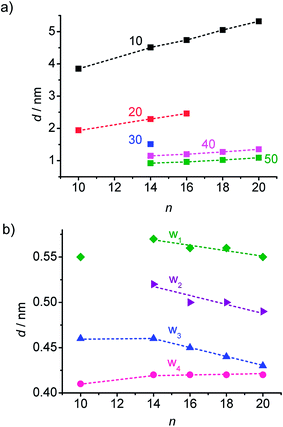 | ||
| Fig. 9 Dependence of the XRD reflex position in the DC phases of compounds A10–A20 on chain length, (a) d-values of the layer reflections with the observed higher harmonics and (b) wide angle scattering maxima, the assignment of the reflections is shown in Fig. 7c, see also Fig. S13–S17.† | ||
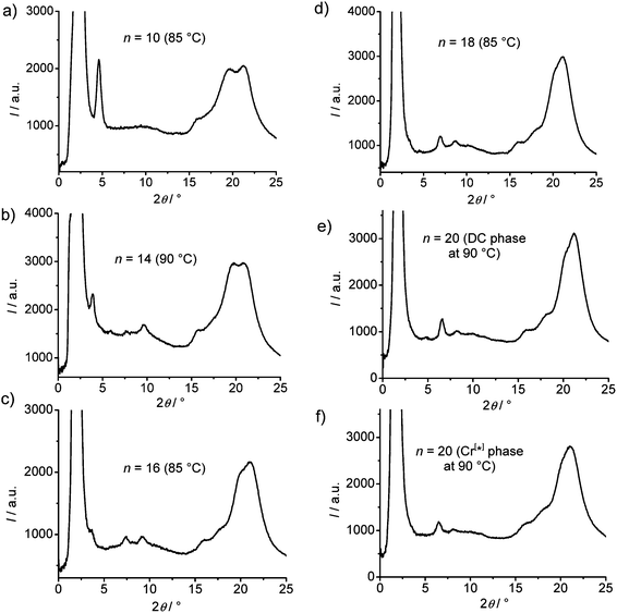
In the medium angle region of the diffraction patterns of compounds A14–A20 there are additional distinct scattering maxima on top of a broad diffuse scattering covering the range between 2θ = 5° and 2θ = 15° (see Fig. 8), only for A10 exclusively the diffuse scattering could be observed. These reflections can be indexed as higher harmonics of the layer reflection (see Fig. 7c), as also found for the HNF phases. In the wide angle range there is a broad feature which could be fitted to 4 maxima (w1–w4) in the 2θ range between 19 and 21° (see Fig. 7c). This pattern excludes fluid sponge phases, showing exclusively a very diffuse wide angle scattering besides the layer reflection. However, it is also distinct from the typical patterns of HNF phases (B4 phases), where the wide angle reflections have other positions and appear as significantly sharper separate peaks.9,20,21
With growing chain length the intensity of the second harmonics of the small angle scattering decreases and it has completely disappeared for compound A18 (Fig. 8), whereas the (50) and (40) reflections increase in intensity, most probably due to the changing electron density modulation resulting from the changing thickness of the aliphatic layers and other structural modifications. There is also a nearly continuous change of the positions of the wide angle scattering (Fig. 8 and 9), indicating continuous structural transformations depending on the chain lengths. An indexing of the wide angle diffraction patterns was not attempted, because of the limited number and the diffuse character of the reflections. Due to the overlapping of several scattering maxima the precise assignment of the positions of the maxima is difficult and the presence of additional scattering in this region cannot be excluded. In any case, the scattering in this region should result from the packing of the crystallized (mainly aromatic) segments on a 2D in-plane lattice. The significant line broadening is thought to be due to the limited correlation length of the crystalline micro-domains.
Major changes can be observed for the scattering w3 occurring around 2θ ∼ 19–20° which decreases in intensity (compare Fig. 8a–e) and is shifted to smaller d-values (see Fig. 9b) from A14 to A20. Based on its d-value in the range between 0.46 and 0.43 nm and its strong intensity dependence on temperature (see discussions below) it is thought that this scattering is most likely due to the mean distance between less ordered (not crystallized) segments of the alkyl chains. The observation that with increasing chain length the position of w3 is shifted to smaller d-values would be in line with a denser chain packing for longer chains.
The temperature effect on the XRD pattern of compound A14 in the DC phase is shown in Fig. 7c. There is no significant influence on the intensities and positions of the scattering maxima with exception of w3 which is strongly reduced at decreased temperature, though its position is retained. Reducing the temperature has obviously a similar effect on the intensity of this scattering like increasing the alkyl chain length. This supports the assumption that this scattering maximum does not belong to the 2D in-plane lattice and could be attributed to the mean distance between the disordered alkyl chain segments. The fraction of the more disordered alkyl chain segments becomes smaller as temperature is reduced and as the alkyl chain length is increased, because longer chains provide a higher tendency for chain crystallization, as mentioned above. This corresponds with the observed strong rise of the DC-Iso transition enthalpy from 24.1 kJ mol−1 for A/10 to 59 kJ mol−1 for A/20 (see Table 1 and Fig. 5a; values on heating). In line with increasing chain crystallization by chain elongation, the optically isotropic DC phase of compound A20 is in competition with a low birefringent crystalline conglomerate phase Cr[*] and exclusively a Cr[*] phase is formed by A22 with the longest chains.
For compound A20 the XRD patterns were recorded at the same temperature (T = 90 °C) after slow cooling (0.5 K min−1Fig. 8e) in the DC phase as well as after fast cooling (10 K min−1Fig. 8f) in the Cr[*] phase. Surprisingly, the two XRD patterns look very similar, only all scattering appear to be a bit broader and have slightly lower intensity in the birefringent Cr[*] phase, though the sample and exposure time were identical. This is reproducibly observed and would suggest a reduced local order in the Cr[*] phase compared to the DC phase. This is in line with the suggested core crystallization as origin of the exotherm (II) occurring on heating at the transition from the birefringent Cr[*] phase to the optically isotropic DC phase (see curve c in Fig. 5d). Because chirality is observed in the birefringent Cr[*] phase as well as in the isotropic DC phase, the aromatic cores should in both phases adopt chiral helical conformations with uniform helix sense, which is opposite in the distinct chiral domains. At the Cr[*]–DC transition the contrast between the dark and bright domains decreases (compare Fig. 6a, e and c, g). This reduced optical activity indicates a reduction of the helical twist of the molecular conformations at the transition from the crystalline to the DC phase. Molecular entities with uniform helix sense cannot be densely packed in nondistorted layers and thus induce twist and curvature. This distortion increases with growing packing density of the helical entities, and therefore the denser core packing leads to a stronger layer deformation force, giving rise to the formation of the optically isotropic DC phase. The birefringent Cr[*] phase, formed on rapid cooling appears to be dominated by optimized alkyl chain packing (chain crystallization), which allows a non-twisted lamellar or modulated lamellar organization of the molecules, but without optimized core-packing. The aromatic cores remain in a strongly twisted helical conformation, leading to a high optical activity, but the strong molecular twist also leads to a disruption of the aromatic layers into smaller domains (see Fig. 6d). Upon heating the Cr[*] phase, the alkyl chain order decreases and a growing fraction of these chains becomes disordered. This allows a denser core packing, simultaneously leading to a reduced helicity of the molecular conformations (reduced optical activity) and, giving rise to a strong layer distortion and formation of the DC phase with an increased alkyl chain disorder. This means that the isotropic DC phases are the result of the optimization of core packing and represent disordered versions of the birefringent crystalline conglomerates (Cr[*] phases), providing improved alkyl chain packing. With rising alkyl chain length the chain crystallization becomes increasingly more important. For compound A20 formation of the optical isotropic DC phase can still be achieved by using sufficiently slow cooling rates, so that the slow core crystallization can take place and determine the structure, leading to the DC phase. On fast cooling, however, densest core packing obviously cannot be achieved and the fast chain crystallization leads to a non-twisted lamellar organization, giving rise to the birefringent conglomerate phase Cr[*] with reduced core order and enhanced optical activity. For compound A22 chain crystallization dominates at all cooling rates, and hence, exclusively a crystalline phase is formed.
Low birefringent crystalline conglomerate phases were also observed for compounds A14–A18, but for these compounds very high cooling rates (≫20 K min−1) are required for their formation and there is apparently always a coexistence of these birefringent Cr[*] phases with the isotropic DC phases, which makes the investigations difficult. Fig. 10 shows representative textures and DSC curves as obtained for compound A16 after rapid cooling (30 K min−1 for the texture and 50 K min−1 before recording the DSC trace a). For these compounds core crystallization is sufficiently fast compared to alkyl chain crystallization and therefore DC phases can be observed for moderate cooling rates. The Cr[*] phases are absent for all shorter homologues starting with A12, which have the smallest contribution of alkyl chain crystallization to the total transition enthalpy value (Fig. 5a); here self-assembly is dominated by optimized core packing, which leads to DC phase formation.
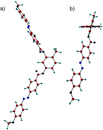
![[double bond, length as m-dash]](https://www.rsc.org/images/entities/char_e001.gif) O groups are nearly coplanar. However, the methyl group at the 4-position at the resorcinol core induces a significant twist of the adjacent carboxyl group together with the coplanar azobenzene wing out of the plane of the resorcinol unit by 72.4°, which is much larger than that of the azobenzene wings adjacent to H-6 (53.6°). This strong twist leads to an overall helical molecular conformation and this is assumed to be responsible for a high tendency for chiral segregation and distorted packing in layers. Though the understanding of the general structure property relations with respect to formation of DC phases is still at the infancy it appears that the presence of relatively flat and rigid aromatic π-systems, as provided by azobenzenes and to some extent also by Schiff base units is favorable for formation of soft crystalline DC phases. So, it appears that π-stacking favours DC phase formation. In the case of the azobenzenes the presence of an additional relatively bulky substituent, such as I, Br or CH3 seems to be required, probably by providing a stronger molecular twist. In contrast, formation of LC sponge type DC phases is favoured for bent-core compounds with more flexible phenylbenzoate wings and having long and flexible or bulky end groups at the termini.8 However, final conclusions cannot be drawn here and require further investigations.
O groups are nearly coplanar. However, the methyl group at the 4-position at the resorcinol core induces a significant twist of the adjacent carboxyl group together with the coplanar azobenzene wing out of the plane of the resorcinol unit by 72.4°, which is much larger than that of the azobenzene wings adjacent to H-6 (53.6°). This strong twist leads to an overall helical molecular conformation and this is assumed to be responsible for a high tendency for chiral segregation and distorted packing in layers. Though the understanding of the general structure property relations with respect to formation of DC phases is still at the infancy it appears that the presence of relatively flat and rigid aromatic π-systems, as provided by azobenzenes and to some extent also by Schiff base units is favorable for formation of soft crystalline DC phases. So, it appears that π-stacking favours DC phase formation. In the case of the azobenzenes the presence of an additional relatively bulky substituent, such as I, Br or CH3 seems to be required, probably by providing a stronger molecular twist. In contrast, formation of LC sponge type DC phases is favoured for bent-core compounds with more flexible phenylbenzoate wings and having long and flexible or bulky end groups at the termini.8 However, final conclusions cannot be drawn here and require further investigations.
![[thin space (1/6-em)]](https://www.rsc.org/images/entities/char_2009.gif) :
:![[thin space (1/6-em)]](https://www.rsc.org/images/entities/char_2009.gif) 1 mixture of A14 with 4′-n-pentyl-4-cyanobiphenyl (5-CB) does not show any DC phase. On heating this mixture only a direct transition from the crystalline material to the isotropic liquid state occurs at 85 °C which is below the DC–Iso transition temperature of pure A14 (T = 101 °C). On cooling this mixture a transition from the isotropic liquid to the nematic phase takes place at T ∼ 54 °C, but no chiral domains can be observed. The nematic phase rapidly crystallizes with formation of a highly birefringent crystalline phase at T ∼ 53 °C (see Table 2 and Fig. S19†).
1 mixture of A14 with 4′-n-pentyl-4-cyanobiphenyl (5-CB) does not show any DC phase. On heating this mixture only a direct transition from the crystalline material to the isotropic liquid state occurs at 85 °C which is below the DC–Iso transition temperature of pure A14 (T = 101 °C). On cooling this mixture a transition from the isotropic liquid to the nematic phase takes place at T ∼ 54 °C, but no chiral domains can be observed. The nematic phase rapidly crystallizes with formation of a highly birefringent crystalline phase at T ∼ 53 °C (see Table 2 and Fig. S19†).
![[thin space (1/6-em)]](https://www.rsc.org/images/entities/char_2009.gif) :
:![[thin space (1/6-em)]](https://www.rsc.org/images/entities/char_2009.gif) 1 mixtures of 5-CB and compounds A14–A22 and B14a
1 mixtures of 5-CB and compounds A14–A22 and B14a
| Mixture | Heating T/°C | Cooling T/°C |
|---|---|---|
| a Transition temperatures were taken from the observed textures using polarized optical microscopy; abbreviations: N = nematic phase, for other abbreviations please see Table 1. | ||
| A14–5-CB | Cr1 39 Cr2 85 Iso | Iso 54 N 53 Cr |
| A16–5-CB | Cr 64 DC 73 Iso | Iso 66 DC |
| A18–5-CB | DC 77 Iso | Iso 72 DC |
| A20–5-CB | DC 80 Iso | Iso 78 DC |
| A22–5-CB | Cr[*] 59 DC 87 Iso | Iso 80 DC 37 Cr[*] |
| B14–5-CB | Cr 63 Iso | Iso 61 Cr |
The longer compounds A16–A20 behave differently; for the 1![[thin space (1/6-em)]](https://www.rsc.org/images/entities/char_2009.gif) :
:![[thin space (1/6-em)]](https://www.rsc.org/images/entities/char_2009.gif) 1 mixtures the DC phases were retained and their temperature ranges increase with growing chain length (Table 2 and Fig. S20†). However, at only slightly higher 5-CB concentration, as for example, in the 4
1 mixtures the DC phases were retained and their temperature ranges increase with growing chain length (Table 2 and Fig. S20†). However, at only slightly higher 5-CB concentration, as for example, in the 4![[thin space (1/6-em)]](https://www.rsc.org/images/entities/char_2009.gif) :
:![[thin space (1/6-em)]](https://www.rsc.org/images/entities/char_2009.gif) 6 mixtures of compounds A16–A20 with 5-CB the chiral DC phase is lost and instead a heterogenous mixture is obtained indicating that the amount of 5-CB which can be mixed into the DC phases of compounds An is strongly limited. So, compared with the HNF phases, the DC phases of compounds An can only be retained if the alkyl chains are sufficiently long, but also in this case much less 5-CB is tolerated. These observations, in conjunction with the XRD studies, confirm that the DC phases of compounds An should be different from the classical HNF phases. It appears that these phases are formed by smaller nano-domains instead of long helical filaments, in line with the results discussed in the previous sections. Because no extended filaments are formed, no gel-like networks of these fibers are possible and therefore these compounds can take up only a limited amount of 5-CB, which is directly incorporated between the bent-core molecules thus reducing the stability of the DC phases.
6 mixtures of compounds A16–A20 with 5-CB the chiral DC phase is lost and instead a heterogenous mixture is obtained indicating that the amount of 5-CB which can be mixed into the DC phases of compounds An is strongly limited. So, compared with the HNF phases, the DC phases of compounds An can only be retained if the alkyl chains are sufficiently long, but also in this case much less 5-CB is tolerated. These observations, in conjunction with the XRD studies, confirm that the DC phases of compounds An should be different from the classical HNF phases. It appears that these phases are formed by smaller nano-domains instead of long helical filaments, in line with the results discussed in the previous sections. Because no extended filaments are formed, no gel-like networks of these fibers are possible and therefore these compounds can take up only a limited amount of 5-CB, which is directly incorporated between the bent-core molecules thus reducing the stability of the DC phases.
Mixing the longest homologue A22, which does not show any DC phase, with 5-CB in 1![[thin space (1/6-em)]](https://www.rsc.org/images/entities/char_2009.gif) :
:![[thin space (1/6-em)]](https://www.rsc.org/images/entities/char_2009.gif) 1 ratio induces a DC phase as an enantiotropic phase between T = 59 °C and 87 °C (see Fig. S21†). This shows that 5-CB can reduce the chain crystallization and thus allow the formation of the DC phase even if the pure compound itself does not show any DC phase. However, no DC phase can be induced in the fluorinated compounds Bn (X = F, 1
1 ratio induces a DC phase as an enantiotropic phase between T = 59 °C and 87 °C (see Fig. S21†). This shows that 5-CB can reduce the chain crystallization and thus allow the formation of the DC phase even if the pure compound itself does not show any DC phase. However, no DC phase can be induced in the fluorinated compounds Bn (X = F, 1![[thin space (1/6-em)]](https://www.rsc.org/images/entities/char_2009.gif) :
:![[thin space (1/6-em)]](https://www.rsc.org/images/entities/char_2009.gif) 1 mixtures with 5-CB) that show polar smectic phases and are discussed in Section 3.5.
1 mixtures with 5-CB) that show polar smectic phases and are discussed in Section 3.5.
3.5 Polar and non-polar smectic phases formed by compounds Bn–Dn with additional peripheral substituents
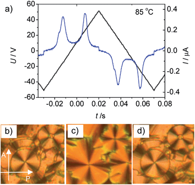
In order to investigate the effect of introducing a lateral substitution on the outer two benzene rings in the periphery of the aromatic core of the bent-core liquid crystals An, related molecules Bn, C14 and D14 were synthesized (Scheme 2). In the series of compounds Bn with X = F all compounds show the same type of mesophase, irrespective of the chain length (see Table 1). As an example, on heating B14 in a homeotropic cell a schlieren texture is observed at T = 90 °C (see Fig. S6a†) indicating the presence of a SmC phase. The relatively high transition enthalpy (ΔH ∼ 12.8 kJ mol−1) is in the range as usually found for polar SmC phases (for representative DSC traces, see Fig. S10†). The presence of two polarization reversal peaks in each half period of an applied triangular wave voltage (160 Vpp, see Fig. 12a) indicate an antiferroelectric switching process. The spontaneous polarization value was calculated to be Ps = 650 nC cm−2 at 85 °C. On cooling the compound in a 6 μm ITO coated cell under an external applied field circular domains are formed (Fig. 12c). At 0 V the position of the extinction crosses is parallel to the polarizers, indicating an anticlinic tilted SmCaPA phase. Under an applied electric field the extinction crosses in the circular domains become inclined to the directions of the polarizers, indicating a field induced synclinic SmCsPF phase. By changing the direction of the applied electric field three distinct states (see Fig. 12b–d) can be clearly observed confirming a tristable switching process by rotation on a cone. Based on these results it is concluded that this is a B2-type polar SmC phase with an anticlinic antiferroelectric SmCaPA ground state structure.Replacing the fluorine substituents in Bn by methyl groups (D14) leads to a monotropic SmC phase (for texture see Fig. S6b†) without polar order, also indicated by the much smaller SmC–Iso transition enthalpy values (0.9 kJ mol−1) and the observation that no current peak could be observed up to a voltage of 200 Vpp in a 6 μm ITO cell. It appears that increasing the size of the peripheral substituents X reduces the packing density significantly, thus leading to strong reduction of mesophase stability in the order H ∼ F > CH3 > Br, at first leading to a loss of polar order for X = CH3 and finally to a complete suppression of all mesophases for X = Br. As the electronegative F atoms increase the polarity of the core region, and hence increase the segregation of the core from the lipophilic alkyl chains, there is no significant mesophase destabilization or a slight stabilization if H is replaced by F (compare A14 and B14 in Table 1). But nevertheless, chiral segregation is removed. The dominance of steric effects of Br and CH3 leads to the loss of polar order and to the lowest LC phase stability for these compounds.
3.6 Effects of replacing the azo groups by ester groups
Aiming to investigate the effects of replacing the azo linking groups in compounds A14 by ester groups, compounds E14, F14 and G14 were synthesized. As shown in Scheme 3, the mesophase exhibited by E14 is enantiotropic with a relatively wide LC range and much higher transition temperatures than found for A14. The texture of the LC phase (Fig. S6c†) is similar to those observed for modulated smectic phases of bent-core mesogens.48 On applying a triangular wave electric field of 160 Vpp to E14 in a 6 μm ITO cell, two polarization reversal peaks can be clearly observed in the switching current response curve (see Fig. S22†) indicating antiferroelectric switching. The spontaneous polarization value, Ps = 310 nC cm−2 at 120 °C is only about one half of that usually observed for SmCPA phases (∼600–800 in the B2 phases) and is in the typical range as observed for modulated SmCPA phases. By changing the direction of the applied electric field (Fig. S23†), no change in the texture could be observed, confirming that the switching process in this mesophase takes place by collective rotation around the long axis of the molecules. This mode of switching is also in line with a modulated structure of this SmCPA phase (Sm![[C with combining tilde]](https://www.rsc.org/images/entities/char_0043_0303.gif) aPA); for a nondistorted flat SmCaPA phase a switching on a cone would be more likely.
aPA); for a nondistorted flat SmCaPA phase a switching on a cone would be more likely.
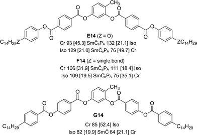 | ||
Scheme 3 Chemical structures of the synthesized 4-methylresorcinol based terephthalates E14, F14 and benzoate G14 with transition temperatures (T/°C) and corresponding enthalpies (ΔH/kJ mol−1, given in square brackets) on heating (top lines) and cooling (bottom lines, both recorded at a rate of 10 K min−1); abbreviations: Sm![[C with combining tilde]](https://www.rsc.org/images/entities/char_0043_0303.gif) aPA = modulated antiferroelectric switching anticlinic SmC phase; Sm aPA = modulated antiferroelectric switching anticlinic SmC phase; Sm![[C with combining tilde]](https://www.rsc.org/images/entities/char_0043_0303.gif) = non-switchable modulated SmC phase with synclinic tilt correlation, for other abbreviations, see Scheme 1 and Table 1; for DSC traces, see Fig. S11.† = non-switchable modulated SmC phase with synclinic tilt correlation, for other abbreviations, see Scheme 1 and Table 1; for DSC traces, see Fig. S11.† | ||
In XRD measurements of compound E14 (Fig. S18†) several equally spaced sharp reflections can be found in the small angle region, indicating a lamellar structure with a d-value of 4.83 nm. The diffuse scattering in the wide angle region shows four intensity maxima beside the equator, from which a tilt angle of the molecules of ∼28° could be calculated. As the extinction crosses are approximately parallel to the polarizers (Fig. S6c†) and an equal intensity of the wide angle scattering is found (Fig. S18a and b†) the tilt correlation should be anticlinic. Though there are indications of layer modulations or undulations from other experimental data, these are not visible in the XRD patterns. Either the modulation wavelength is very long, so that the layer reflections are not resolved into separate reflections, or the reflections with h and k ≠ 0 are too weak to be detected with the used XRD setup.
Replacing the terminal alkoxy chains in E14 by alkyl chains in compound F14 (see Scheme 3, for DSC traces see Fig. S11a†) leads to a compound with about 20 K lower clearing temperature which can also be assigned as Sm![[C with combining tilde]](https://www.rsc.org/images/entities/char_0043_0303.gif) aPA based on the observed textures and measured Ps values (Ps = 300 nC cm−2 at 95 °C, see Fig. S24†). The major difference between the two compounds is the inclination of the dark extinctions upon applying an electric field (Fig. S25†), indicating that the switching process in this case takes place on a cone; so probably the modulation wavelength of F14 is larger than for E14.
aPA based on the observed textures and measured Ps values (Ps = 300 nC cm−2 at 95 °C, see Fig. S24†). The major difference between the two compounds is the inclination of the dark extinctions upon applying an electric field (Fig. S25†), indicating that the switching process in this case takes place on a cone; so probably the modulation wavelength of F14 is larger than for E14.
Inverting the direction of the terminal ester group in compound G14 (see Scheme 3) further reduces the transition temperatures, which are now similar to those of the azobenzene derivative A14 (for DSC traces see Fig. S11b†). Also in this case the texture is similar to those of some modulated smectic phases (Fig. S6d†). The position of the extinction crosses is inclined with the orientation of the polarizers and thus indicates a synclinic tilted organization of the molecules. In electrooptic studies (160 Vpp in a 6 μm ITO cell) no current response can be detected. This might be due to a shorter modulation wavelength than in the case of E14, which is known to suppress polar switching or would require very high voltages. Also the observation of a uniform synclinic tilt would be in line with a B1rev-like modulated SmC phase with an oblique lattice. However, it was not possible to further confirm the proposed phase structure by XRD due to the rapid crystallization. Overall, replacing the azobenzene wings by terephthalates (E14, F14) or benzoates (G14) removes the DC phases and leads to polar and apolar smectic phases with a significant tendency for layer modulation or undulation.
4. Conclusions and summary
New bent-core liquid crystalline materials combining 4-methylresorcinol with azobenzene wings were synthesized and investigated. The short homologues (n = 6–8) exhibit intercalated smectic phases (B6 phases) which upon increasing the chain length (n = 9–20) convert to DC phases and for the longest homologue (n = 22) only a crystalline phase was observed. For compound A20 formation of the optically isotropic DC phase is in competition with formation of a low birefringent crystalline conglomerate (Cr[*]) and the observed phase type is strongly dependent on the cooling rate. It appears that formation of the Cr[*] phase is favored by chain crystallization, whereas in the isotropic DC phases core crystallization is dominating. Based on the XRD patterns and high viscosity the DC phases of compounds An belong to the soft crystalline DC phases, but they are distinct from the previously reported B4-type HNF phases by the absence of extended filaments as indicated by the results of their mixtures with 5-CB.Introduction of additional substituents at the outer rings of the bent-core molecules An removes the DC phases and replaces them first by polar smectic phases (X = F, SmCaPA). Upon further enlargement of these substituents (X = CH3) also polar order is removed, yielding a non-polar SmC phase which is then removed for the compound with the largest substituent X = Br. Replacing the azo groups by ester groups in the related terephthalates or benzoates also removes the DC phases and leads to different types of modulated SmC phases which in most cases show polar switching.
Overall, new modifications of isotropic as well as birefringent conglomerate phases were observed and the relationship between molecular structure and formation of these phases was identified. It appears that the azobenzene unit is a specially powerful tool for introducing new types of chiral conglomerate phases, distinct from the typical B4 type phases found for benzylidene imines. There seems to be a whole zoo of different types of these DC phases, ranging from the fluid B2-like sponge phases to several distinct types of soft crystalline phases, including modulated subtypes;49–51 obviously only a small fraction of the potential structures has been explored yet. Moreover, the possibilities provided by introduction of the photoisomerizable azobenzene units into BCLC forming DC phases could lead to interesting perspectives for chirality switching and phase modulation, leading to unique and potentially useful multifunctional chiral materials for application in chiral discrimination of chiral physical forces and molecular species22 and as non-centrosymmetric materials.
Acknowledgements
M. Alaasar is grateful to the Alexander von Humboldt Foundation for the research fellowship at the Martin-Luther University Halle-Wittenberg, Germany.References
- T. Sekine, T. Niori, J. Watanabe, T. Furukawa, S. W. Choi and H. Takezoe, J. Mater. Chem., 1997, 7, 1307 RSC.
- (a) R. A. Reddy and C. Tschierske, J. Mater. Chem., 2006, 16, 907 RSC; (b) H. Takezoe and Y. Takanishi, Jpn. J. Appl. Phys., Part 1, 2006, 45, 597 CrossRef CAS; (c) G. Pelzl, S. Diele and W. Weissflog, Adv. Mater., 1999, 11, 707 CrossRef CAS; (d) C. Tschierske, Angew. Chem., Int. Ed., 2013, 52, 8828 CrossRef CAS PubMed; (e) V. Görtz and J. W. Goodby, Chem. Commun., 2005, 3262 RSC; (f) G. Pelzl and W. Weissflog, in Thermotropic Liquid Crystals, ed. A. Ramamoorthy, Springer, The Netherlands, 2007, pp. 58–83 Search PubMed; (g) I. Dierking, Angew. Chem., Int. Ed., 2010, 49, 29 CrossRef CAS PubMed; (h) A. Eremin and A. Jákli, Soft Matter, 2013, 9, 615 RSC.
- D. R. Link, G. Natale, R. Shao, J. E. Maclennan, N. A. Clark, E. Körblova and D. M. Walba, Science, 1997, 278, 1924 CrossRef CAS.
- (a) J. Harden, B. Mbanga, N. Eber, K. Fodor-Csorba, S. Sprunt, J. T. Gleeson and A. Jákli, Phys. Rev. Lett., 2006, 97, 157802 CrossRef CAS; (b) A. C. Charif, N. Diorio, K. Fodor-Csorba, J. E. Puskásad and A. Jákli, RSC Adv., 2013, 3, 17446 RSC.
- (a) W. Iglesias, T. J. Smith, P. B. Basnet, S. R. Stefanovic, C. Tschierske, D. J. Lacks, A. Jákli and E. K. Mann, Soft Matter, 2011, 7, 9043 RSC; (b) W. Iglesias, N. L. Abbott, E. K. Mann and A. Jákli, ACS Appl. Mater. Interfaces, 2012, 4, 6884 CrossRef CAS PubMed.
- J. Etxebarria and M. B. Ros, J. Mater. Chem., 2008, 28, 2919 RSC.
- M. Nagaraj, Y. P. Panarin, J. K. Vij, C. Keith and C. Tschierske, Appl. Phys. Lett., 2010, 97, 213505 CrossRef PubMed.
- (a) G. Dantlgraber, A. Eremin, S. Diele, A. Hauser, H. Kresse, G. Pelzl and C. Tschierske, Angew. Chem., Int. Ed., 2002, 41, 2408 CrossRef CAS; (b) G. Dantlgraber, S. Diele and C. Tschierske, Chem. Commun., 2002, 2768 RSC; (c) C. Tschierske and G. Dantlgraber, Pramana, 2003, 61, 455 CrossRef CAS; (d) C. Keith, R. A. Reddy, A. Hauser, U. Baumeister and C. Tschierske, J. Am. Chem. Soc., 2006, 128, 3051 CrossRef CAS PubMed; (e) C. Keith, R. A. Reddy, U. Baumeister, H. Hahn, H. Lang and C. Tschierske, J. Mater. Chem., 2006, 16, 3444 RSC; (f) H. Hahn, C. Keith, H. Lang, R. A. Reddy and C. Tschierske, Adv. Mater., 2006, 18, 2629 CrossRef CAS; (g) C. Keith, G. Dantlgraber, R. A. Reddy, U. Baumeister, M. Prehm, H. Hahn, H. Lag and C. Tschierske, J. Mater. Chem., 2007, 17, 3796 RSC; (h) C. Keith, G. Dantlgraber, R. A. Reddy, U. Baumeister and C. Tschierske, Chem. Mater., 2007, 19, 694 CrossRef CAS; (i) Y. Zhang, U. Baumeister, C. Tschierske, M. O'Callaghan and C. Walker, Chem. Mater., 2010, 2869 CrossRef CAS; (j) H. Ocak, B. Bilgin-Eran, M. Prehm and C. Tschierske, Soft Matter, 2012, 8, 7773 RSC.
- L. E. Hough, M. Spannuth, M. Nakata, D. A. Coleman, C. D. Jones, G. Dantlgraber, C. Tschierske, J. Watanabe, E. Körblova, D. M. Walba, J. E. Maclennan, M. A. Glaser and N. A. Clark, Science, 2009, 325, 452 CrossRef CAS PubMed.
- G. Heppke, D. D. Parghi and H. Sawade, Liq. Cryst., 2000, 27, 313 CrossRef CAS.
- J. Thisayukta, Y. Nakayama, S. Kawauchi, H. Takezoe and J. Watanabe, J. Am. Chem. Soc., 2000, 122, 7441 CrossRef CAS.
- (a) R. A. Reddy and B. K. Sadashiva, Liq. Cryst., 2003, 30, 1031 CrossRef; (b) A. Roy, M. Gupta, S. Radhika, B. K. Sadashiva and R. Pratibha, Soft Matter, 2012, 8, 7207 RSC.
- (a) J. Ortega, C. L. Folcia, J. Etxebarria, N. Gimeno and M. B. Ros, Phys. Rev. E: Stat., Nonlinear, Soft Matter Phys., 2003, 68, 11707 CrossRef CAS; (b) N. Gimeno, A. Sanchez-Ferrer, N. Sebastian, R. Mezzenga and M. B. Ros, Macromolecules, 2011, 44, 9586 CrossRef CAS.
- M. Nagaraj, K. Usami, Z. Zhang, V. Görtz, J. W. Goodby and H. F. Gleeson, Liq. Cryst., 2014, 41, 800 CrossRef CAS.
- (a) A. Jákli, Y.-M. Huang, K. Fodor-Csorba, A. Vajda, G. Galli, S. Diele and G. Pelzl, Adv. Mater., 2003, 15, 1606 CrossRef; (b) W. Weissflog, M. W. Schröder, S. Diele and G. Pelzl, Adv. Mater., 2003, 15, 630 CrossRef CAS.
- (a) L. E. Hough, H. T. Jung, D. Krüerke, M. S. Heberling, M. Nakata, C. D. Jones, D. Chen, D. R. Link, J. Zasadzinski, G. Heppke, J. P. Rabe, W. Stocker, E. Körblova, D. M. Walba, M. A. Glaser and N. A. Clark, Science, 2009, 325, 456 CrossRef CAS PubMed; (b) D. M. Walba, L. Eshat, E. Körblova and R. K. Shoemaker, Cryst. Growth Des., 2005, 5, 2091 CrossRef CAS; (c) D. Chen, J. E. Maclennan, R. Shao, D. K. Yoon, H. Wang, E. Körblova, D. M. Walba, M. A. Glaser and N. A. Clark, J. Am. Chem. Soc., 2011, 133, 12656 CrossRef CAS PubMed.
- (a) J. Thisayukta, H. Takezoe and J. Watanabe, Jpn. J. Appl. Phys., Part 1, 2001, 40, 3277 CrossRef CAS; (b) H. Niwano, M. Nakata, J. Thisayukta, D. R. Link, H. Takezoe and J. Watanabe, J. Phys. Chem. B, 2004, 108, 14889 CrossRef CAS; (c) H. Kurosu, M. Kawasaki, M. Hirose, M. Yamada, S. Kang, J. Thisayukta, M. Sone, H. Takezoe and J. Watanabe, J. Phys. Chem. A, 2004, 108, 4674 CrossRef CAS.
- H. Kresse, J. Saltetnokova, H. Nadasi, W. Weissflog and A. Hauser, Liq. Cryst., 2001, 28, 1017 CrossRef CAS.
- V. Prasad, Liq. Cryst., 2001, 28, 1115 CrossRef CAS.
- H. Nadasi, C. Lischka, W. Weissflog, I. Wirth, S. Diele, G. Pelzl and H. Kresse, Mol. Cryst. Liq. Cryst., 2003, 399, 69 CrossRef CAS.
- J. Martinez-Perdiguero, I. Alonso, C. L. Folcia, J. Etxebarria and J. Ortega, J. Mater. Chem., 2009, 15, 5161 RSC.
- H. Takezoe, Top. Curr. Chem., 2012, 318, 303 CrossRef CAS.
- D. K. Yoon, Y. Yi, Y. Shen, E. D. Körblova, D. M. Walba, I. I. Smalyukh and N. A. Clark, Adv. Mater., 2011, 23, 1962 CrossRef CAS PubMed.
- J. Ortega, N. Pereda, C. L. Folcia, J. Etxebarria and M. B. Ros, Phys. Rev. E: Stat. Phys., Plasmas, Fluids, Relat. Interdiscip. Top., 2000, 63, 011702 CrossRef.
- G. Lee, R. J. Carlton, F. Araoka, N. L. Abbott and H. Takezoe, Adv. Mater., 2013, 25, 245 CrossRef CAS PubMed.
- E. Bialecka-Florjanczyk, I. Sledzinska, E. Górecka and J. Przedmojski, Liq. Cryst., 2008, 35, 401 CrossRef CAS.
- (a) S.-W. Choi, T. Izumi, Y. Hoshino, Y. Takanishi, K. Ishikawa, J. Watanabe and H. Takezoe, Angew. Chem., Int. Ed., 2006, 45, 1382 CrossRef CAS PubMed; (b) G. Lee, R. J. Carlton, F. Araoka, N. L. Abbott and H. Takezoe, Adv. Mater., 2013, 25, 245 CrossRef CAS PubMed.
- M. Alaasar, M. Prehm and C. Tschierske, Chem. Commun., 2013, 49, 11062 RSC.
- I. C. Pintre, J. L. Serrano, M. B. Ros, J. M.Perdiguero, I. Alonso, J. Ortega, C. Folcia, J. Etxebarria, R. Alicantee and B. Villacampa, J. Mater. Chem., 2010, 20, 2965 RSC.
- Y. Zang, J. Martinez-Perdiguero, U. Baumeister, C. Walker, J. Etxebirra, M. Prehm, J. Ortega, C. Tschierske, M. O'Calleghan, A. Harant and M. Handschy, J. Am. Chem. Soc., 2009, 131, 18366 CrossRef PubMed.
- (a) H. G. Heller and J. R. Langan, J. Chem. Soc., Perkin Trans. 1, 1981, 2, 341 RSC; (b) P. Schmitz, H. Gruler and M. Eberhardt, Mol. Cryst. Liq. Cryst., 1995, 262, 129 CrossRef.
- (a) V. Prasad, S.-W. Kang and S. Kumar, J. Mater. Chem., 2003, 13, 1259 RSC; (b) V. Prasad and A. Jákli, Liq. Cryst., 2004, 31, 473 CrossRef CAS; (c) V. Prasad, S.-W. Kang, X. Qi and S. Kumar, J. Mater. Chem., 2004, 14, 1495 RSC; (d) A. Jákli, V. Prasad, D. S. S. Rao, G. Liao and I. Janossy, Phys. Rev. E: Stat., Nonlinear, Soft Matter Phys., 2005, 71, 02170911 CrossRef; (e) N. G. Nagaveni, A. Roy and V. Prasad, J. Mater. Chem., 2012, 22, 8948 RSC; (f) C. L. Folcia, I. Alonso, J. Ortega, J. Etxebarria, I. Pintre and M. B. Ros, Chem. Mater., 2006, 18, 4617 CrossRef CAS; (g) I. C. Pintre, N. Gimeno, J. L. Serrano, M. B. Ros, I. Alonso, C. L. Folcia, J. Ortega and J. Etxebarria, J. Mater. Chem., 2007, 17, 2219 RSC; (h) J. Etxebarria and M. B. Ros, J. Mater. Chem., 2008, 18, 2919 RSC; (i) I. C. Pintre, J. L. Serrano, M. B. Ros, J. M. Perdiguero, I. Alonso, J. Ortega, C. L. Folcia, J. Etxebarria, R. Alicante and B. Villacampa, J. Mater. Chem., 2010, 20, 2965 RSC; (j) M. Vijaysrinivasan, P. Kannan and A. Roy, Liq. Cryst., 2012, 39, 1465 CrossRef CAS.
- (a) M. Alaasar, M. Prehm, M. Nagaraj, J. K. Vij and C. Tschierske, Adv. Mater., 2013, 25, 2186 CrossRef CAS PubMed; (b) M. Alaasar, M. Prehm, K. May, A. Eremin and C. Tschierske, Adv. Funct. Mater., 2013, 24, 1703 CrossRef.
- (a) M. Alaasar, M. Prehm and C. Tschierske, Liq. Cryst., 2013, 40, 656 CrossRef CAS; (b) M. Alaasar, M. Prehm and C. Tschierske, Liq. Cryst., 2014, 41, 126 CrossRef CAS.
- cv = crystal volumes, calculated using the increments of A. Immirzi: A. Immirzi and B. Perini, Acta Crystallogr., Sect. A: Cryst. Phys., Diffr., Theor. Gen. Crystallogr., 1977, 33, 216 CrossRef.
- Very few examples of BCLCs based on 4-methylresorcinol have been reported previously: (a) U. Dunemann, M. W. Schröder, R. A. Reddy, G. Pelzl, S. Diele and W. Weissflog, J. Mater. Chem., 2005, 15, 4051 RSC; (b) W. Weissflog, G. Pelzl, H. Kresse, U. Baumeister, K. Brand, M. W. Schröder, M. G. Tamba, S. Findeisen-Tandel, U. Kornek, S. Stern, A. Eremin, R. Stannarius and J. Svoboda, J. Mater. Chem., 2010, 20, 6057 RSC.
- C. Keith, A. Lehmann, U. Baumeister, M. Prehm and C. Tschierske, Soft Matter, 2010, 6, 1704 RSC.
- M. J. Frisch, et al., Gaussian 09, Revision A.1, Gaussian Inc., Wallingford CT, 2009 Search PubMed.
- (a) S. Kang, M. Tokita, Y. Takanishi, H. Takezoe and J. Watanabe, Phys. Rev. E: Stat., Nonlinear, Soft Matter Phys., 2007, 76, 042701 CrossRef; (b) S. Kang, S. K. Lee, M. Tokita and J. Watanabe, Phys. Rev. E: Stat., Nonlinear, Soft Matter Phys., 2009, 80, 042703 CrossRef.
- Also dielectric studies confirm the similarity of the B6 phases having short-range ordered ribbons with the B1 phases formed by a long range 2D lattice of ribbons: H. Kresse, H. Schmalfuss and W. Weissflog, Liq. Cryst., 2001, 28, 799 CrossRef CAS.
- The electron density modulation occurs between the regions where alkyl chains are mixed with the central units of the bent cores (low electron density) and the regions with overlapping parts of the rod-like wings (high electron density).
- Due to this overlapping of phase transition and crystallization the transition enthalpy values could not be determined for the B6–DC transition.
- I. Dierking, Liq. Cryst. Today, 2003, 12, 1 CrossRef CAS.
- The difference of the transition temperatures in the cooling curves b and d in Fig. 5c and d is mainly due to the very different cooling rate used.
- A similar texture was recently described for mixtures of B4 phases with nematic LC and was interpreted as an alignment of the helical nanofilaments by the nematic director, we think that in our case this texture has different origin and indicates a crystalline conglomerate phase: F. Araoka, G. Sugiyamam, K. Ishikawa and H. Takezoe, Adv. Funct. Mater., 2013, 23, 2701 CrossRef CAS.
- The molecular length in the Chevron shaped conformation (see Fig. S1†) was used for calculations; a partial intercalation of the alkyl chains, leading to a reduced tilt angle, cannot be excluded.
- T. Otani, F. Araoka, K. Ishikawa and H. Takezoe, J. Am. Chem. Soc., 2009, 131, 12368 CrossRef CAS PubMed.
- R. A. Reddy, U. Baumeister, C. Keith and C. Tschierske, J. Mater. Chem., 2007, 17, 62 RSC.
- H. Ocak, B. Bilgin-Eran, M. Prehm and C. Tschierske, Soft Matter, 2013, 9, 4590 RSC.
- I. Miyake, Y. Takanishi, N. V. S. Rao, M. K. Paul, K. Ishikawa and H. Takezoe, J. Mater. Chem., 2005, 15, 4688 RSC.
- E. Tsai, J. M. Richardson, E. Körblova, M. Nakata, D. Chen, Y. Shen, R. Shao, N. A. Clark and D. M. Walba, Angew. Chem., Int. Ed., 2013, 52, 5254 CrossRef CAS PubMed.
Footnote |
| † Electronic supplementary information (ESI) available. See DOI: 10.1039/c4tc00533c |
| This journal is © The Royal Society of Chemistry 2014 |

