On the interplay of shell structure with low- and high-frequency mechanics of multifunctional magnetic microbubbles†
Melanie
Poehlmann
a,
Dmitry
Grishenkov
bc,
Satya V. V. N.
Kothapalli
b,
Johan
Härmark
de,
Hans
Hebert
de,
Alexandra
Philipp
a,
Roland
Hoeller
a,
Maximilian
Seuss
a,
Christian
Kuttner
a,
Silvia
Margheritelli
f,
Gaio
Paradossi
f and
Andreas
Fery
*a
aDepartment of Physical Chemistry II, University of Bayreuth, Universitätsstraße 30, DE-95440 Bayreuth, Germany. E-mail: andreas.fery@uni-bayreuth.de; Fax: +49 (0)921 552059; Tel: +49 (0)921 552751
bDivision of Medical Engineering, School of Technology and Health, KTH, Royal Institute of Technology, Sweden
cKarolinska Institutet, Department of Clinical Science, Intervention and Technology, Huddinge, Sweden
dDivision of Structural Biotechnology, School of Technology and Health, KTH, Royal Institute of Technology, Sweden
eKarolinska Institutet, Department of Biosciences and Nutrition, Huddinge, Sweden
fDepartment of Chemical Sciences and Technologies, University of Rome Tor Vergata, Rome, Italy
First published on 11th October 2013
Abstract
Polymer-shelled magnetic microbubbles have great potential as hybrid contrast agents for ultrasound and magnetic resonance imaging. In this work, we studied US/MRI contrast agents based on air-filled poly(vinyl alcohol)-shelled microbubbles combined with superparamagnetic iron oxide nanoparticles (SPIONs). The SPIONs are integrated either physically or chemically into the polymeric shell of the microbubbles (MBs). As a result, two different designs of a hybrid contrast agent are obtained. With the physical approach, SPIONs are embedded inside the polymeric shell and with the chemical approach SPIONs are covalently linked to the shell surface. The structural design of hybrid probes is important, because it strongly determines the contrast agent's response in the considered imaging methods. In particular, we were interested how structural differences affect the shell’s mechanical properties, which play a key role for the MBs' US imaging performance. Therefore, we thoroughly characterized the MBs' geometric features and investigated low-frequency mechanics by using atomic force microscopy (AFM) and high-frequency mechanics by using acoustic tests. Thus, we were able to quantify the impact of the used SPIONs integration method on the shell’s elastic modulus, shear modulus and shear viscosity. In summary, the suggested approach contributes to an improved understanding of structure–property relations in US-active hybrid contrast agents and thus provides the basis for their sustainable development and optimization.
1 Introduction
Hybrid imaging offers new diagnostic and therapeutic procedures and pushes the development of novel multifunctional contrast agents.1–10 The successive use of ultrasound (US) and magnetic resonance imaging (MRI) is standard in today's clinical routine, because they provide complementary information and operate without ionizing radiation.Hence, it is not surprising that a combination of both modalities for hybrid imaging is in sight.11–14 However, there exist difficult and specific imaging situations where conventional US and/or MRI imaging is limited and enhanced contrast is required.15 Therefore, contrast agents are used such as gas-filled microbubbles (MBs) to enhance the US signal15–17 and paramagnetic complexes or superparamagnetic nanoparticles to enhance the MRI signal.18–20 Novel emerging diagnostics and therapies plus well-established imaging procedures give good reasons for the growing interest in producing adequate hybrid contrast agents visible in both modalities.21–26 The major challenges in developing new US/MRI contrast agents are the different functional requirements that hybrid probes need to match. For US/MRI imaging, hybrid probes need sufficient stability during the circulation in the cardiovascular system,27 an adequate US echo signal,28 and a reasonable reduced relaxation time of nearby located protons.29 All these requirements have a direct impact on the structural design of the probes. For example, the upper size is limited to about 7 μm,27 because the contrast agent needs to pass capillary beds within the cardiovascular system. As a lower size limit, 100 nm is recommended to avoid any leakage through the endothelium and a response from the immune system.30–33 However, the particle diameter or more precisely the gas volume trapped inside the particles also matters for the acoustic response.27 For basic applications like Doppler imaging, a backscatter signal value of about 20 dB is needed.34 Moreover, the contrast agent requires enough stability to cross the pulmonary capillary bed and facilitate adequate imaging times. A common solution to increase the MBs' stability is the use of low water solubility gases that are encapsulated by shells made of lipids, proteins or polymers.35–37 On the one hand, the shell provides the platform for further functionalizations of ultrasound responsive MBs to hybrid probes and thus is a crucial design element. For US/MRI contrast, the shell is used for the integration of magnetic complexes or nanoparticles.10,38–40 On the other hand, the shell is also a well-known drawback for the acoustic response, because it decreases the backscatter signal, depending on the shell material and shell thickness.28,41 With regard to the final imaging performance of multimodal contrast agents all these different structural elements need to be considered and adjusted during the production of probes. Therefore, we believe that a straightforward analysis of structure–property relationships is essential when hybrid contrast agents are developed or optimized.
In the focus of this study are recently presented23 US/MRI contrast agents, which have a 3 μm sized air-bubble stabilized by a shell made of poly(vinyl alcohol) (PVA) as a common feature.42,43 In this article, a microbubble without any magnetic nanoparticles is referred to as plain MB as sketched in Fig. 1. Plain MBs are already well characterized regarding the option to carry therapeutic gases43,44 and the possibility of introducing molecules relevant for targeting or drug delivery.45 Moreover, for plain MBs the echogenicity,46–49 biocompatibility50 and cytotoxicity51 were studied. Magnetic MBs were obtained either by physical or chemical integration of superparamagnetic iron oxide nanoparticles (SPIONs) to the plain MBs. The physical method52 yields MBs with SPIONs embedded inside the shell, which are referred to as MBs-phys. The chemical approach23 yields MBs with SPIONs attached covalently to the shell surface, referred to as MBs-chem. Recently, we reported on the synthesis process, weight percent of integrated SPIONs and US- and MR-imaging properties of these particles.23 The magnetic properties of the particles were studied in vitro using a SQUID system showing a higher net magnetization for MBs-phys compared to MBs-chem. The change in magnetization was attributed to different aggregation states of the SPIONs in the two samples. In vivo, magnetic properties were tested in rats for proof of concept by using clinical MRI equipment. These experiments were analyzed regarding spin–spin relaxation times and rates for different tissues.
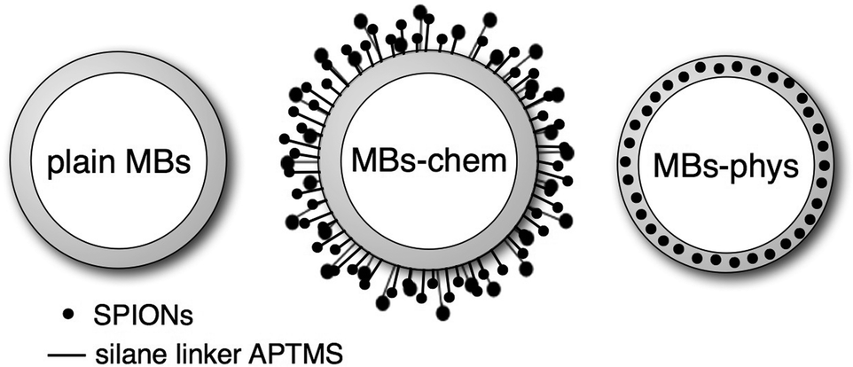 | ||
| Fig. 1 Schematic of plain MBs (MBs without SPIONs), MBs-chem with SPIONs covalently attached to the shell surface and MBs-phys with SPIONs physically embedded inside the shell. | ||
This work focuses on the MBs’ mechanical properties, which play a key role for the US imaging performance. In particular, we were interested if the SPION-integration method has an impact on the MB's low- and high-frequency mechanics. To bridge the gap between the contrast agents' synthesis and their final performance, a straightforward analysis of structure–property relationships is crucial. Therefore, we first studied the influence of the manufacturing process on basic geometric properties, such as MB diameter and shell thickness. In the next step, the mechanical properties in the low- and high-frequency regime (low: 2 Hz, high: 2–14 MHz) were studied. Low-frequency experiments were performed with quasi-static force measurements of single microbubbles using atomic force microscopy (AFM). Sboros and co-workers53–56 already showed that AFM is a useful tool to study the mechanical properties of hard-shelled ultrasound contrast agents with a bilayer shell made of albumin and polylactide. Recently, AFM force spectroscopy experiments have been successfully used for the characterization of phospholipid-shelled MBs.57–59 High frequency mechanics of the US/MRI contrast agent were investigated by exposure of an ensemble of MBs to an acoustic field.60,61 As a result, we obtained the elastic modulus of the shell material from low-frequency mechanics and the shear modulus of the shell material from high-frequency mechanics. This straightforward characterization of ultrasound contrast agents contributes to an improved understanding of structure–property relationships and offers the possibility for a sustainable design of hybrid contrast agents.
2 Materials and methods
Materials
Iron chloride hexahydrate (FeCl3·6H2O, purity > 99%), iron chloride tetrahydrate (FeCl2·4H2O, purity > 99%), rhodamine B isothiocyanate (RBITC), (3-aminopropyl) trimethoxysilane (APTMS), sodium cyanoborohydride (NaBH3CN), and sodium (meta)periodate (NaIO4) were products from Sigma Aldrich, Milan, Italy. Low molecular weight chitosan (CHIT), with a Brookfield viscosity of 20![[thin space (1/6-em)]](https://www.rsc.org/images/entities/char_2009.gif) 000 cP, number-averaged molecular weight of 50 ± 5 kg mol−1, and poly(vinyl alcohol) (PVA) with a number-averaged molecular weight of 30 ± 5 kg mol−1 determined by membrane osmometry and mass-averaged molecular weight of 70 ± 10 kg mol−1 determined by static light scattering were purchased from Sigma Aldrich, Milan, Italy. An acetylation degree of chitosan of 15% (mol/mol repeating units) was determined by 1H NMR at 300 MHz (Bruker Advance, Germany). Inorganic acids and bases were reagent grade products from Carlo Erba, Milan, Italy. Milli-Q water with purity grade 18.2 MΩ cm−1 was produced with a deionization apparatus (PureLab, Steroglass, PG, Italy).
000 cP, number-averaged molecular weight of 50 ± 5 kg mol−1, and poly(vinyl alcohol) (PVA) with a number-averaged molecular weight of 30 ± 5 kg mol−1 determined by membrane osmometry and mass-averaged molecular weight of 70 ± 10 kg mol−1 determined by static light scattering were purchased from Sigma Aldrich, Milan, Italy. An acetylation degree of chitosan of 15% (mol/mol repeating units) was determined by 1H NMR at 300 MHz (Bruker Advance, Germany). Inorganic acids and bases were reagent grade products from Carlo Erba, Milan, Italy. Milli-Q water with purity grade 18.2 MΩ cm−1 was produced with a deionization apparatus (PureLab, Steroglass, PG, Italy).
Synthesis of SPIONs
SPIONs (Fe3O4) with an average particle diameter of 8–10 nm were prepared using controlled co-precipitation described previously.23 Briefly, 5 mL of an aqueous solution of 1 M FeCl3·6H2O, 0.5 M FeCl2·4H2O, and 0.4 M HCl were added under vigorous mechanical stirring (2000 rpm) to 50 mL of 0.5 M NaOH. After heating the alkaline solution to 80 °C, the reaction was carried out for 30 min under a N2 atmosphere to prevent oxidation. The particles were collected by sedimentation with the help of a large magnetic stirring bar, washed with degassed water and ethanol, and dried in vacuum. For the coupling of SPIONs to non-reacted aldehyde groups available on the MB surface, amino groups were introduced to the SPIONs' surface via silanization. Therefore, 100 mg of SPIONs were washed with methanol (20 mL), then with a mixture of methanol and toluene (20 mL; 1:1, v/v), and finally with toluene alone (20 mL). SPIONs were then dispersed into 20 mL toluene. APTMS [0.5 mL, 3 mM, in a methanol–toluene (1:1, v/v) mixture] was added to the SPION suspension, followed by a further reflux of the suspension at 110 °C for 24 h under a N2 flow and vigorous stirring. The modified particles were magnetically collected, washed three times with methanol, and vacuum dried.
Synthesis of plain MBs
The synthesis has already been previously reported by Cavalieri et al.42 Briefly, sodium metaperiodate was added to an aqueous PVA solution (2% w/v) to selectively split vicinal hydroxyl groups. Shorter chains of PVA with aldehydes as terminal groups were obtained. An acetalization reaction between aldehyde and hydroxyl groups present in the PVA chains was carried out at a pH of 5.5 and room temperature under high shear stirring, using an Ultra-Turrax T-25 (IKA, Germany) equipped with a Teflon tip, at 8000 rpm for 2 h. The master concentration received for evaluation is 1.4 × 108 MB per mL.Synthesis of magnetic MBs-chem
For the coupling of SPIONs to the plain MBs' shell, a weight ratio between plain MBs and silanized SPIONs of 1:2 (w/w) was used. First SPIONs were sonicated for 90 min in an US bath (Ultrasound cleaner CP104, CEIA, Italy). Then 20 mg mL−1 SPIONs were added to 10 mg of plain MBs. The reductive amination was carried out at a pH of 5.0 with NaBH3CN. The suspension was gently shaken for 5 days and washed with Milli-Q water. Chitosan oxidation was carried out by dissolving the polymer in water at a concentration of 1% (w/v) at pH 5.5, oxidizing the C2 and C3 carbons of the chitosan-repeating unit for 1 day with NaIO4 (feed molar ratio GlcN/NaIO4 1:0.5, where GlcN indicates the glucosamine-repeating unit in the chitosan chain). Following conjugation with silanized SPIONs, the oxidized-repeating units of chitosan are coupled to hydroxyl groups of the PVA shells by mixing a dispersion of 5 mg of MBs with 13 mL of the chitosan solution. The master concentration received for evaluation is 1.75 × 108 MB per mL. The amount of SPIONs was analyzed by thermogravimetric analysis (TGA) and found to be 29 %w/w for MBs-chem.23
Synthesis of magnetic MBs-phys
Unmodified SPIONs were physically embedded in the shell by exploiting the favourable interaction between iron oxide nanoparticles and PVA.52 Briefly, SPIONs were suspended in water at a concentration of 5 mg mL−1 and sonicated for 90 min in an ultrasonic bath (see above). 20 mg mL−1 SPIONs were added during the PVA shell formation. The rest of the synthesis is according to the synthesis of plain MBs. The master concentration received for evaluation is 4 × 108 MB per mL. The amount of SPIONs was analyzed by TGA and found to be 15 %w/w for MBs-phys.23Optical microscopy
A sample of MBs was inserted into a Neubauer Chamber improved (Carl Roth, Germany). Images of the floating MBs were obtained under Koehler illumination with an Axiovert 200 (Plan Neofluar Objective, 20×/0.50 Ph2) using a high-resolution monochrome camera (AxioCam HRm) from Carl Zeiss AG, Germany. The resolution of the pictures was 1300 × 1030 pixels (1.935 pixel per μm). To determine the size distribution the images were further analyzed with ImageJ software.62 First, the brightness and contrast of the images were automatically corrected and then a binary with automated threshold was made. The particles considered for analysis were particles with a minimum area of 3.41 μm2 (diameter 1 μm) and a maximum area of 25 μm2 (diameter 8 μm), to exclude small and larger residues from the polymerization reaction. The edges were excluded from the image analysis.Transmission electron microscopy
Using TEM (CEM 902, Carl Zeiss AG, Germany) thin sections of about 50 nm to 60 nm, produced using an ultracut microtome (EM UC7, Leica Mikrosysteme Vertrieb GmbH, Germany), were imaged at 80 kV. The shell thickness was obtained from TEM images by extracting cross-sectional gray-value profiles that were analyzed with ImageJ software.62 The start/end of the shell was determined at 50% decrease/increase of the gray-value intensity. TEM samples were prepared by mixing the capsule solution in a 1:1 ratio with 2% aqueous solution of agar (Agar Noble, Difco, USA). After curing, the flexible gel was cut with a scalpel into small cubes. Next, the agar-embedded capsules were solidified by 1 h incubation with a 2% glutaraldehyde solution (Serva Electrophoresis GmbH, Germany) in phosphate buffer (0.05 M phosphate buffer, pH 7.4 Merck KGaA, Germany). Afterwards three washing steps with phosphate buffer were used to remove the excess of glutaraldehyde. Then the samples were dehydrated in ethanol–water mixtures with increasing ethanol content (30%/50%/70%/95%) and three times in plain ethanol (VWR International GmbH, Germany). The dehydration exposure time was 15 min for each step. The dried samples were then mixed with Epon 812 (Serva Electrophoresis GmbH, Germany): Epon 812/ethanol mixture (1:1) for 12 h, followed by an Epon 812/ethanol mixture (3:1) for 3–4 h and finished with three immersion steps (3–4 h) in 100% Epon 812.
Atomic force microscopy – imaging
Gas-filled polymeric MBs were imaged with an AFM Nanowizard I (JPK Instruments AG, Germany) mounted on a transmission microscope (Axiovert 200, Carl Zeiss AG, Germany). Prior to the measurement, MBs were exposed for 20 min to an ultrasonic bath at room temperature. This treatment leads to a replacement of the gas-filled core by the surrounding water. Water-filled particles will fold flat upon drying on a substrate. MBs were dried for 15 min in a vacuum at 60 °C. After the sample preparation, MBs were directly imaged by AFM. Dried MBs were imaged in intermittent modulus with rectangular cantilevers purchased from Atomic Force, Germany (Olympus, OMCL-AC160TS (OTESPA), f = 300 kHz, k = 42 N m−1). To determine the shell thickness of hydrated MBs, the dried and imaged MBs were immersed for 30 min in purified water (Millipore Advantage, Merck AG, Germany). 30 min were enough to ensure a hydration state and constant heights of the measured MBs. Hydrated MBs were imaged in aqueous solution and in contact mode (CSC17, Mikromasch, Estonia, f = 12 kHz, k = 0.15 N m−1). The height images were used to extract four cross-section profiles by a standardized analysis with the commercially available AFM software JPK Data Processing.Atomic force microscopy – force spectroscopy
The deformation behaviour of MBs was measured in force spectroscopy experiments with the same AFM used for imaging (Nanowizard I, JPK Instruments AG, Germany). Prior to calibration, tipless cantilevers (CSC12, MikroMasch, Estonia, f = 75 kHz, k = 0.60 N m−1) were cleaned in air plasma (5 min, Mini Flecto, Plasma Technology GmbH, Germany). Then, the inverse optical lever sensitivity (InvOLS) was determined on a hard substrate at least at three different spots with a reasonable displacement of the cantilever (∼1 μm), which is needed to fit the linear regime and read out the InvOLS in V nm−1. With thermal noise63 the spring constant of the cantilevers was determined. Colloidal probes64 (∼40 μm, glass beads, Polyscience Europe GmbH, Germany) were attached with the help of a micromanipulator (MP-285, Sutter Instrument Co., CA, USA) to the cantilever tip with an epoxy glue (UHU plus endfest 300, UHU GmbH & Co KG, Germany). Prior to the MB deformation experiments, the colloidal probe cantilevers were cleaned for 5 min in air plasma.Acoustic characterization
The experimental setup used to assess the acoustic properties of the MB suspension has already been described elsewhere.47 In brief, a flat transducer with nominal frequency f = 10 MHz and −20 dB bandwidth ranging between 2.55 MHz and 14.5 MHz is used. An aluminium block, which is positioned 1 cm away from the sample container, is used as a reflector. Within the near-field length (D2/(4λ) = 280 mm, where D is the diameter of the transducer crystal and λ is the ultrasound wavelength in the medium of propagation), this transducer produced a pressure field with a peak negative pressure not larger than 20 kPa. The peak negative pressure was assessed by using a PVdF 75 μm needle hydrophone (Precision Acoustics Ltd., Dorchester, Dorset, UK). More information on the determination of the attenuation coefficient can be found in the ESI.†Microbubble concentration
It has been previously reported23 that the acoustic efficiency, i.e. backscattered power, is proportional to the number of scatterers (here MBs) in the suspension if the excitation is performed below the resonance frequency and multiple scattering is disregarded. As a result, we propose to evaluate all types of MBs at three different concentrations: low, intermediate and high concentration. For plain MBs the concentrations were 1.75 × 105 MB per mL, 8.75 × 105 MB per mL, and 1.75 × 106 MB per mL. For MBs-chem, concentrations of 4.37 × 105 MB per mL, 8.75 × 105 MB per mL, and 1.75 × 106 MB per mL were used. And for MBs-phys, concentrations of 5 × 105 MB per mL, 1 × 106 MB per mL, and 2 × 106 MB per mL were considered. Minor discrepancies between the number of bubbles taken for each investigation is attributed to the fact that the dilution rate was kept constant among all tests while the master solution arrived at different initial concentrations.Differential scanning calorimetry
The crystallinity of PVA was investigated using a TAQ200 (Waters, Milan, Italy) differential scanning calorimeter (DSC). A known amount of 2–3 mg of lyophilized MBs was sealed in an aluminum pan. The scans were performed from 50 °C to 250 °C at heating and cooling rates of 10 °C min−1 under a flux of 50 mL min−1 of dry N2. Data were collected after the first reference thermal cycle.3 Results and discussion
Geometrical dimensions of magnetic MBs
PVA-shelled MBs have a diameter of about 3 μm as shown in the optical micrograph and the corresponding size distribution in Fig. 2. Optical micrographs are useful for quality control and to estimate roughly the average diameter of the MBs.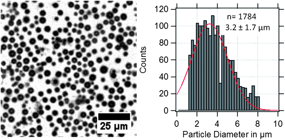 | ||
| Fig. 2 Optical micrograph of US/MRI contrast agents (MBs-phys) dispersed in water with the corresponding size distribution. | ||
However, the obtained size distributions do not only represent the MBs' size dispersity but also include a deviation caused by the error of the method. In the case of gas-filled MBs, the particles are floating at the water–air interface and can move in x, y, and z-directions. Thus, the obtained standard deviation broadens due to MBs that appear smaller by moving out of the focusing plane or appear bigger by overlapping with other MBs in different planes.
To model low- and high-frequency mechanics the MBs' diameter, shell thickness, and the corresponding standard deviations are of paramount importance. Therefore, a method is required that provides precise information about the dispersity of both parameters. By AFM imaging the simultaneous characterization of the diameter and shell thickness is possible, with a sufficiently high resolution in the relevant micrometer and nanometer range.
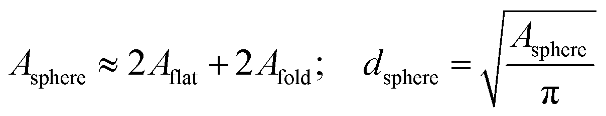
In Fig. 3, typical AFM height images of dried magnetic MBs are shown. Important for the determination of the shell thickness is a flat folded topography of the MB. This is realized by removal of the gas-core through a vacuum drying process, which is described in detail in the Experimental section. For flat folded MBs, we expect the shell thickness H to refer to half of the measured height y, as depicted in the cross-sectional profiles in Fig. 3. The diameter dsphere of the spherical MBs was estimated from the surface area Aflat of the flat folded MBs by assuming that the surface area of the spherical MB Asphere is approximately twice the surface area of the flat folded MB Aflat and twice the area of the folds Afold
 | (1) |
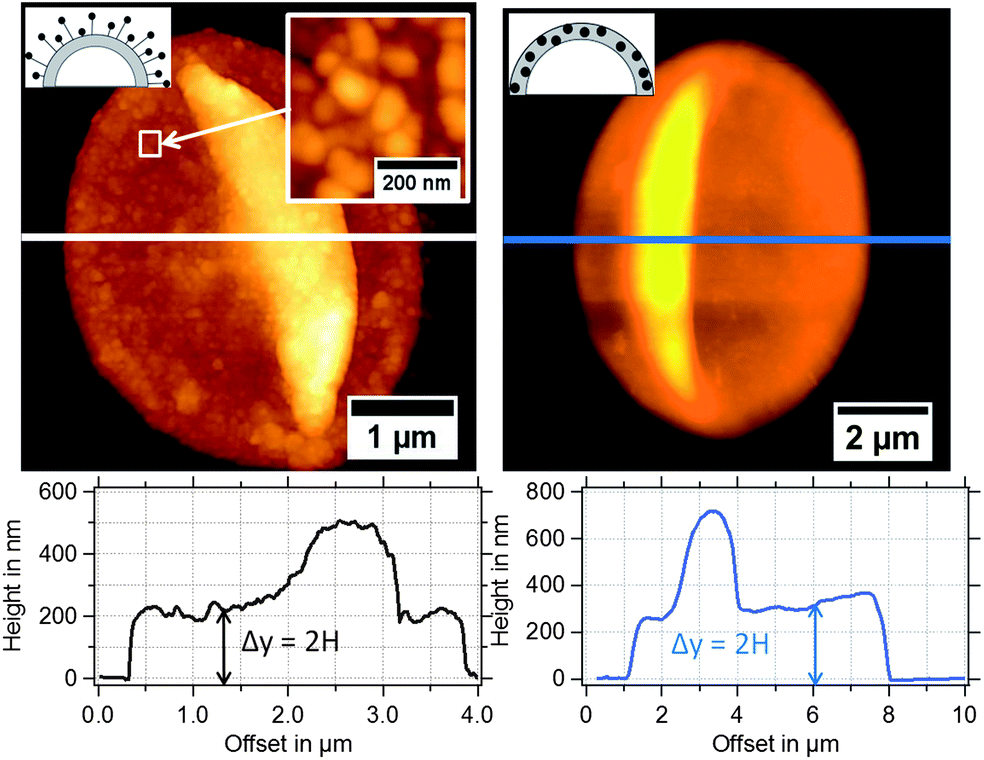 | ||
| Fig. 3 AFM height images of magnetic MBs with the corresponding extracted height profiles: (left) MBs-chem with SPIONs on the shell surface and (right) MBs-phys with SPIONs inside the shell. | ||
In Fig. 4, the shell thickness of the individually studied MBs is plotted against their corresponding diameter. The scatter plot illustrates that the thickness does not depend on the MB diameter. The obtained shell thicknesses scatter around a mean value. Based on this result we conclude that the geometric dimensions of the magnetic MBs did not change through the modification with magnetic nanoparticles and are the same for all three samples. Thus, plain MBs, MBs-chem, and MBs-phys were summarized for the statistical analysis of the shell thickness and the diameter, shown in the histogram in Fig. 5. The average diameter of the MBs is about 3.5 μm ± 0.8 μm and the average shell thickness is about 150 nm ± 60 nm for the dried shell. Detailed values for the statistical median and the peak value of the Gaussian distribution with their corresponding standard deviations are given in Table S1 in the ESI.† An important result from the analysis of the geometrical parameters is that both shell thickness and diameter have a certain polydispersity. To interpret force spectroscopy results and minimize uncertainties the in situ determination of the MBs diameter on the single-particle-level using optical microscopy is essential. However, the shell thickness is not accessible in situ and an average value needs to be considered. In addition to geometric parameters, the AFM images contain information about the MBs' surface structure. The inset in Fig. 3 indicates an increased roughness of the shell surface for MBs-chem compared to MBs-phys, caused by the SPIONs and SPION aggregates on the shell surface.
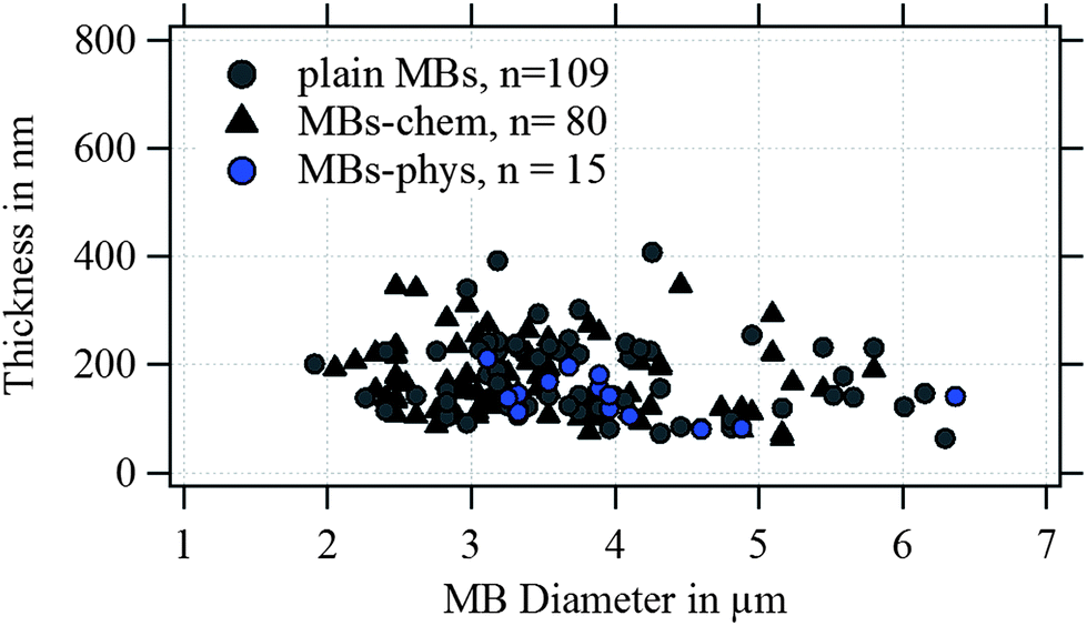 | ||
| Fig. 4 Thickness plotted versus the diameter of the MBs imaged by AFM under dried conditions. | ||
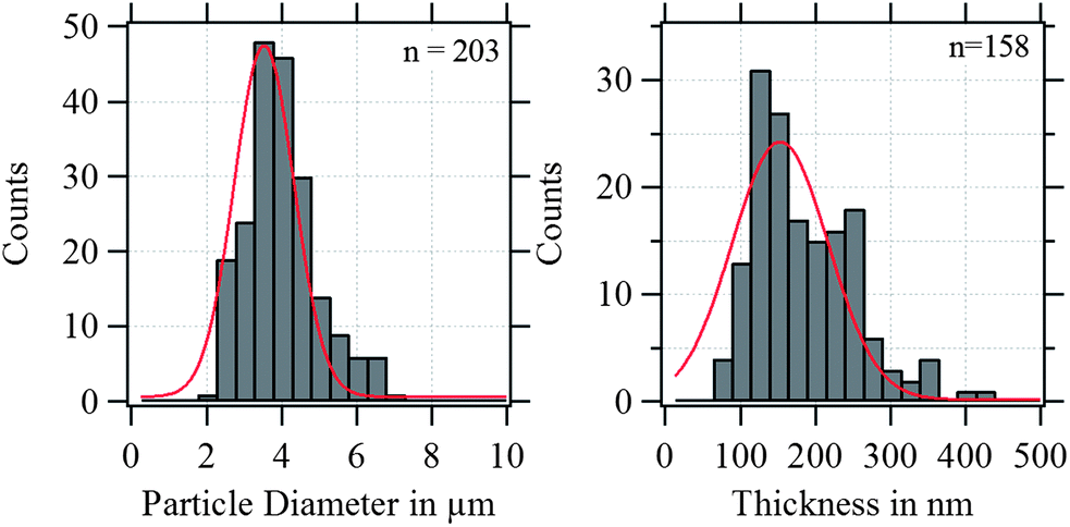 | ||
| Fig. 5 Diameter and shell thickness distribution of plain MBs, MBs-chem, and MBs-phys. | ||
Shells made of telechelic PVA are known to be responsive towards water and are described as a hydrogel-like material. Previous studies by Scanning Transmission X-ray Microscopy (STXM) indicate a shell composition of 20% PVA and 80% water.65,66 STXM images were also used to estimate the shell thicknesses of three individual MBs in water. As a result, the authors found thickness values of 380 nm, 560 nm, and 630 nm.67,68 Tzvetkov et al.69 showed that both thickness and shell composition were maintained after the MBs experienced a drying step. In this study, we analyzed the change of the MBs' shell thickness from dried to hydrated condition. Therefore, dried MBs were exposed to aqueous solution and subsequently imaged by AFM in solution as described in the Experimental section.
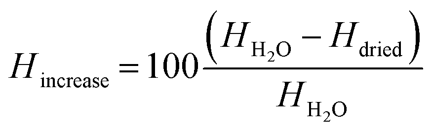
A percental increase of the shell thickness Hincrease of about 45% was observed, which refers to a shell thickness of about 250 nm ± 127 nm calculated from eqn (2):
 | (2) |
This result is in very good agreement with previously reported STXM68 and cryo-TEM69,70 results. A summary of diameter and shell thickness values measured using different methods in this study and in previous work is reported in Table 1.
| Diameter d | |||
|---|---|---|---|
| Method | AFM | Optical | Confocal |
| Dried-state (μm) | 3.5 ± 1.1 | — | — |
| In solution (μm) | 3.6 ± 1.3 | 3.2 ± 1.7 | 4.1 ± 0.6 |
Because the shell thickness is a very important parameter for the MBs' mechanical properties and the acoustic behaviour, we used TEM as a complementary method to validate the results obtained from AFM. In our previous work,23 TEM was successfully used to localize the SPIONs within the thin sections of magnetic MBs. SPIONs can be easily recognized as dark spots in the TEM images, because iron atoms have a high electron density. In Fig. 6, SPIONs are located around the shell surface of MBs-chem and inside the polymer shell for MBs-phys. In addition, the spherical PVA shell can be clearly differentiated from the surrounding resinous matrix (EPON) in which MBs were embedded.
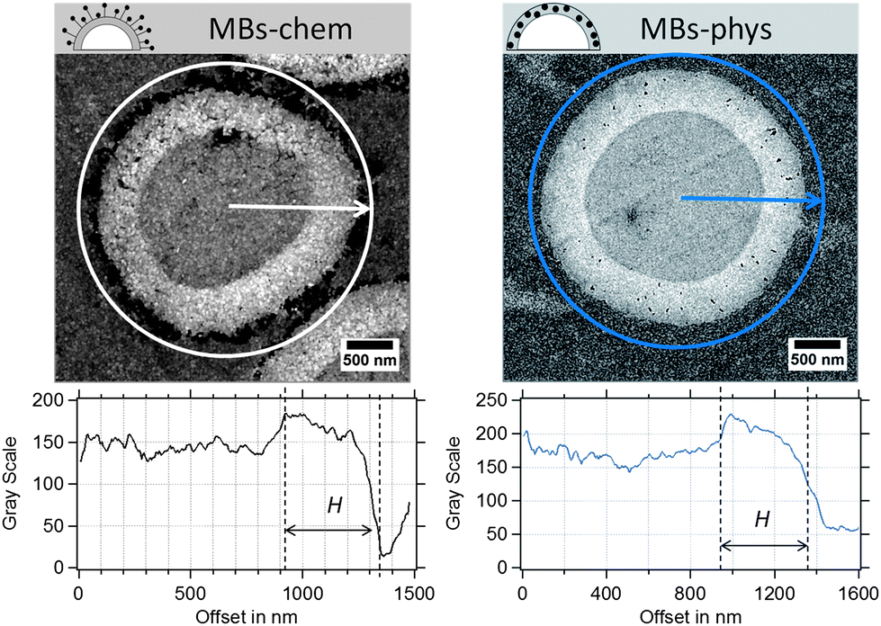 | ||
| Fig. 6 Ultrathin sections of magnetic MBs, MBs-chem and MBs-phys imaged by TEM and the corresponding radial profiles of the gray value intensity. | ||
From contrast-corrected images, as described in Fig. S2,† cross-sectional radial profiles of the gray value intensity were used to determine the shell thickness (see Fig. 6). The edges of the shell are assumed to be at ±50% change of the gray-scale value of the PVA/EPON interface. However, the random slicing process will affect the measured shell thickness Hi and the measured radii Ri. Hence, the sections, which are derived from an increasing distance from the MB's equatorial center, will provide larger shell thicknesses and smaller radii compared to the true values. A modified model based on Smith's correction approach71 was used to derive a correction factor for the measured shell thickness. The correction considers the diameter and thickness distributions obtained from the TEM images and the probability of the slicing at different distances to the capsule's equator within a limiting slicing angle. Further details on the modification can be found in the ESI.†
MBs with a plain PVA shell indicated a mean thickness of about 300 nm. For the magnetic MBs, similar thickness distributions were obtained that did not significantly differ from plain MBs. As a correction factor, we calculated a value of 0.72 for the investigated samples. Based on the found correction factor the true shell thickness is expected to be about 190 nm to 230 nm, which is in good agreement with the results obtained in the AFM experiments and the results reported in the literature. In conclusion, we know that the shell thickness ranges between 120 nm and 230 nm and that we have to expect certain dispersity in the shell thickness.
Mechanical characterization by AFM
Sboros and co-workers53–56 have already made clear that the geometric dimensions and mechanical properties of MBs are crucial for the prediction of the MBs' acoustic behaviour, and that AFM is a useful tool to study the mechanical properties of ultrasound contrast agents (UCAs) in force-deformation experiments. Their focus was mainly on hard-shelled UCAs with a shell made of a bilayer of albumin and polylactide. Recently, AFM force spectroscopy experiments have been successfully used for the characterization of phospholipid-shelled MBs.57–59 One distinctive feature compared to previous mechanical studies on UCAs is the detailed characterization of our investigated system regarding the mechanical key parameters: diameter, shell thickness, and size dispersity. Furthermore, the probe used for the quasi-static deformation of UCAs in the low-frequency regime differs. Instead of a sharp tip, we used a colloidal probe setup,64 which is well-established for mechanical tests on artificial microcapsules.72–75One practical advantage of a colloidal probe setup for mechanical tests of core/shell particles is an easy and optimal alignment of the probe and sample. In addition, a defined contact area is obtained and local probing or indentation is avoided. In Fig. 7, the inset sketches the used setup. The colloidal probe diameter is about 30 μm and thus one order of magnitude larger than the investigated MBs. To test the mechanical response of the MB's shell material, we carried out small deformations on the order of the hydrated shell thickness, referring to deformations smaller than 250 nm. For larger deformations, we expect stretching and thinning of the shell due to an increasing gas volume within the gas-tight MBs, which will lead to additional restoring forces.73,76 To identify the relative deformation ε, where volume forces start to dominate the MB deformation behavior Fery et al.73 suggested a simple scaling argument for capsules that considers the shell thickness H and the radius R:
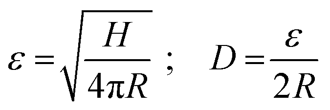 | (3) |
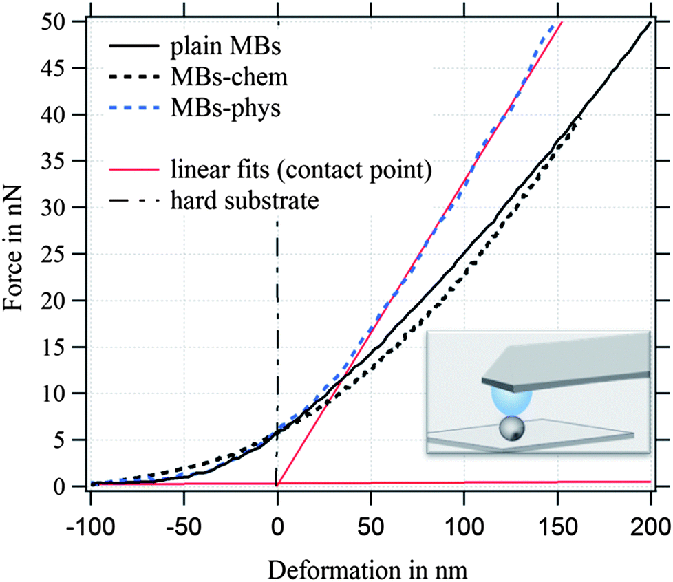 | ||
| Fig. 7 Force-deformation curves of plain MBs, MBs-chem, and MBs-phys. | ||
For the investigated MBs with a radius of ∼1.75 μm and an average hydrated shell thickness of 215 nm, we expect the crossover of these two regimes for a deformation D of about 350 nm. Fig. 7 shows typical force deformation curves of plain MBs, MBs-chem, and MBs-phys. The maximum applied force load was 50 nN that resulting in deformations of up to 250 nm. The curve progression is similar for all three samples and shows after a small non-linear onset a characteristic linear elastic deformation behavior. We believe that the onset observed in the force deformation curves is caused by various surface interactions such as steric repulsion of the PVA chains.
The interface between the gas core and the aqueous solution is the PVA shell, which is described as a hydrogel-like material of 20% polymer and 80% water. From previous published freeze fracture images,69 we distinguished the shell in a polymer-rich zone around the core and a polymer-poor zone close to the aqueous phase, where PVA chains can also penetrate the aqueous phase. Differences in the MBs' deformation behavior are observed when we compare the force load needed for a deformation of 200 nm. MBs with comparable diameter were chosen for Fig. 7 to exclude size effects. The force load needed for a 200 nm deformation of MBs-chem was 26 nN which is much lower compared to a force of 41 nN needed for MBs-phys. The corresponding stiffness F/D of the MBs is given in N m−1, shown as red linear fit in the force–deformation curve.
AFM is combined with optical microscopy to obtain the diameter of each deformed MB. In Fig. 8, the statistical analysis of the observed diameter and the stiffness of the studied particles are displayed. All MBs had a diameter between 1 μm and 3 μm. MBs-chem showed average stiffness values of about 0.03 N m−1 which were smaller than the stiffness values of 0.08 N m−1 for plain MBs. Much larger stiffness values with much broader distributions were observed for MBs-phys with an average stiffness value of about 0.26 N m−1. Thus we can conclude that MBs-chem are much softer than MBs-phys.
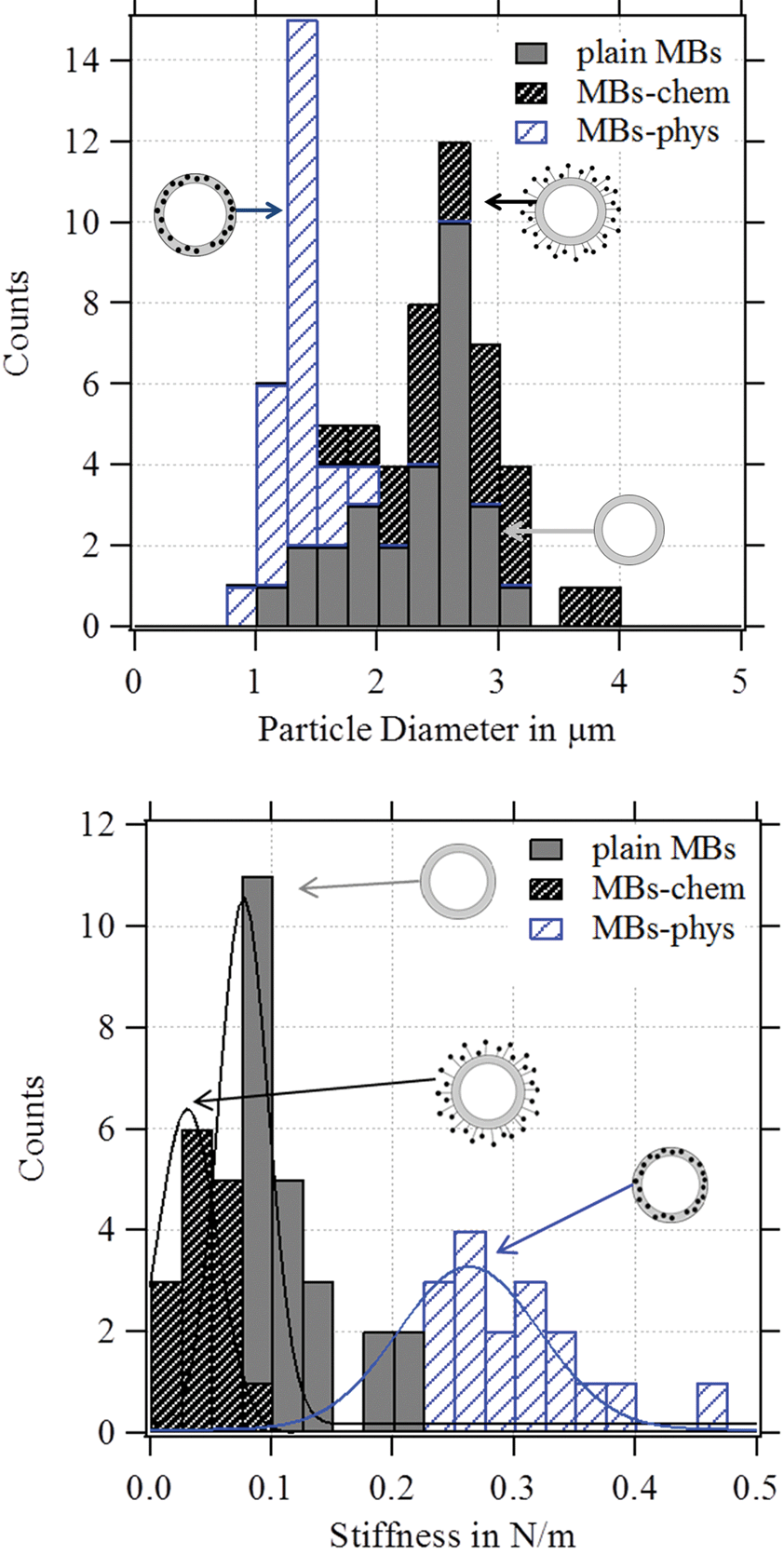 | ||
| Fig. 8 Histogram of the MB stiffness and the particle diameter of the measured MBs. | ||
Whether the observed change in the stiffness is a result of changed material properties of the shell was further analyzed with a model proposed by Reissner.77,78 With this model, the deformation behavior of single MBs can be related to their geometry properties and the shell's material properties can be estimated. The stiffness F/D depends on shell thickness H, radius R, elastic modulus E and the Poisson's ratio ν as described in eqn (4):
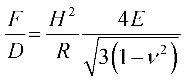 | (4) |
As expected from the Reissner model, we observe an increase of the measured stiffness values for MBs with smaller radius as shown in Fig. 9. The scattering of the stiffness around the proposed linear trend can be attributed to the dispersity that we expect for the shell thickness. MBs-chem are softer compared to plain MBs and surface-modified MBs-phys. To estimate the elastic modulus of the shell's material, we used an approximated average shell thickness of 249 nm for the hydrated state.
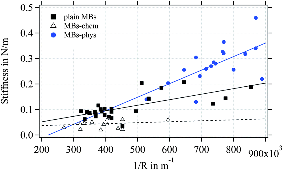 | ||
| Fig. 9 Scattering plot of the stiffness in N m−1versus the inverse of the MB radius. | ||
The Poisson's ratio ranges for materials between 0.49 for rubber-like materials and 0.33 for solid materials. For the calculation of the elastic modulus of the rather soft polymeric shell, we used a reasonable Poisson's ratio of 0.49. As a result, we obtained an elastic modulus of 230 kPa for MBs-chem, 1.3 MPa for plain MBs, and about 3.2 MPa for MBs-phys. These results clearly indicate that the material properties have changed through the modification by SPIONs. As shown by eqn (4), the value of the Poisson's ratio has a minor effect on the elastic modulus compared to the direct measured parameters such as the shell thickness and the radius. Here, the change of the stiffness results in an increase of the elastic modulus.
Internal shell structure
For the MBs' mechanical properties, the shell structure and in particular the density of crosslinks inside the polymeric network are crucial. Both types of crosslinks – chemical and physical – need to be considered for a shell made of poly(vinyl alcohol).79 For the MBs' polymeric shell, chemical crosslinks originate from the acetalization reaction carried out during the MB synthesis, where aldehyde groups of the telechelic PVA react with hydroxyl groups. Non-covalent or physical cross-links refer to crystalline domains within the polymeric network, which are typical for the semicrystalline polymer PVA.80,81The degree of crystallinity, referring to the crystalline domains present in the polymeric network, was determined by differential scanning calorimetry (DSC). Endothermic and exothermic peaks in the DSC diagram refer to the melting and recrystallization of the crystalline domains in the polymeric network. Thus, the degree of crystallinity is accessible, which is an indicator of the number of physical crosslinks inside the PVA shell. Recently,23 we observed differences in the degree of crystallinity between plain MBs, MBs-chem, and MBs-phys as shown in Fig. 10, which is adapted from Brismar et al.23 Plain MBs showed the highest degree of crystallinity with typical endothermic and exothermic peaks. A major change of the number of physical crosslinks was found for SPIONs conjugated to the shell surface (MBs-chem). The typical peak profile is lost indicating the absence of crystalline domains in the PVA network and a complete loss of the physical crosslinks, which is reducing the overall crosslinking density. In contrast, the embedding of SPIONs (MB-phys) resulted in slight changes of the shell structure. Here, a decrease of peak signals was observed, referring to a lower degree of crystallinity and a reduced number of physical crosslinks.
Further experiments were performed in this study to understand the reason for the change of the shell structure and the MBs' mechanical stability. Therefore, we analyzed the degree of crystallinity of plain MBs before and after the chemical treatment. SPIONs were excluded from the chemical treatment; in other words, MBs were solely exposed to the corresponding chemicals and reaction conditions without using any nanoparticles. As Fig. 11 shows, plain MBs indicate the typical peaks referring to the crystalline domains in the network. After exposing the MBs to the reaction conditions and corresponding chemicals the peaks (crystalline domains) are lost. Plain MBs with APTMS attached to the surface show the same internal shell structure as MBs-chem. Thus, we can conclude from these experiments that the chemical treatment is the crucial factor for changes in the internal shell structure.
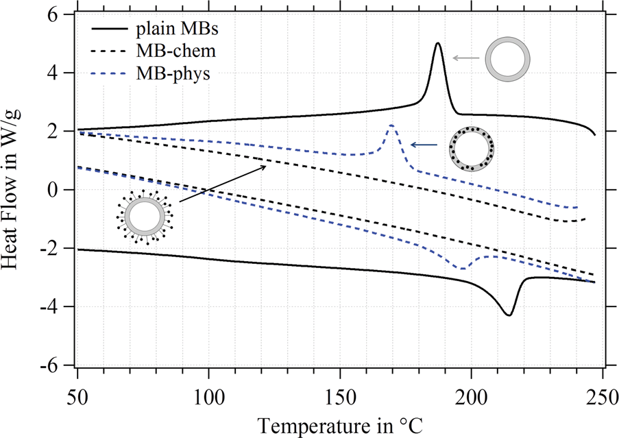 | ||
| Fig. 10 Differential scanning calorimetry of plain MBs (full line), MBs-chem (dashed black line) and MBs-phys (dashed blue line). The diagram was adapted with permission from Brismar et al. Magnetic Nanoparticles can be coupled to Support Multimodal Imaging, Biomacromolecules 13(5), 1390. Copyright (2012) American Chemical Society. | ||
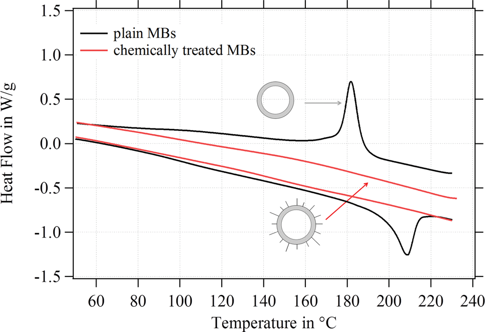 | ||
| Fig. 11 DSC results for plain MBs before and after chemical treatment without attaching SPIONs. | ||
In view of the mechanical properties of MBs-chem, the reduced number of physical crosslinks in the PVA shell is an explanation for the reduced elastic modulus of the shell.79 However, the DSC result for MBs-phys, indicating a reduced number of physical crosslinks, cannot explain the shell's increased elastic modulus. MBs-phys showed the highest elastic modulus of all three MB types. Here, the impact of nanoparticle embedment inside a polymeric network needs to be considered as well. For polymeric nanocomposites, reinforcement upon nanoparticle integration is well-known.82–85 For PVA hydrogels reinforcement was observed for the addition of graphene,86 silver nanoparticles86 and silica particles,87 which all resulted in an increase of the elastic modulus. For other capsule systems, the reinforcement of e.g. polyelectrolyte multilayer shells after incorporation of gold nanoparticles88 or yttrium fluoride89 nanoparticles was reported.
Acoustical characterization – experiments and modeling
The acoustical characterization of MBs in vitro is crucial to bridge the gap between structure–property relationships obtained from AFM studies and the application-relevant performance of the MBs during ultrasound imaging. While we concentrated in the AFM experiments on low-frequency mechanics of single MBs, we focused on the acoustic tests on high-frequency mechanics of an ensemble of MBs. In particular, we were interested whether the MB's mechanical properties observed during quasi-static AFM deformation experiments set the trend for the MB's dynamic oscillation during ultrasound exposure. As already previously reported on plain MBs47 and magnetic MBs,23 both demonstrate a backscatter enhancement of about 20 dB at concentrations approved for commercially available UCAs.90An interesting outcome of the previous study was the finding that MBs-chem reach the 20 dB backscatter enhancement already for a lower concentration (4.4 × 105 MB mL−1) compared to MBs-phys (2 × 106 MB mL−1). Moreover, the attenuation coefficient was smaller for MBs-chem than for MBs-phys. Based on the results of the structural characterization and low-frequency mechanics, we expect that the different mechanical properties of the shell are decisive for the changes in the MBs' acoustic behaviour. In other words, we think that the different SPION integration methods used for the production of MBs-chem and MBs-phys alter shell mechanics and the corresponding acoustic behaviour.
To understand the impact of the low-frequency mechanics on the MB behaviour in the high-frequency regime, we performed further acoustic studies. Moreover, we used the acoustic experiments to estimate the viscoelastic properties of the polymeric shell. In particular, we were interested in the shell's shear modulus Geq and the shear viscosity μ0. The ultrasound experiments were carried out in vitro and under controlled conditions as explained in the Experimental section. First, we measured the frequency dependence of the attenuation coefficient. Fig. 12 shows the observed results for plain MBs, MBs-chem, and MBs-phys. For each MB sample, we acquired data for a low, intermediate, and high MB concentration. As expected, the attenuation coefficient shifts to higher values with an increasing MB concentration, because the number of scatterers is increased in the suspension.23,47 In general, a monotonic increase of the attenuation coefficient is expected when the frequency is raised from 3 MHz to 14 MHz. We identified the following changes in the curve progression with regard to the slope and the maximum absolute value of the attenuation coefficient.
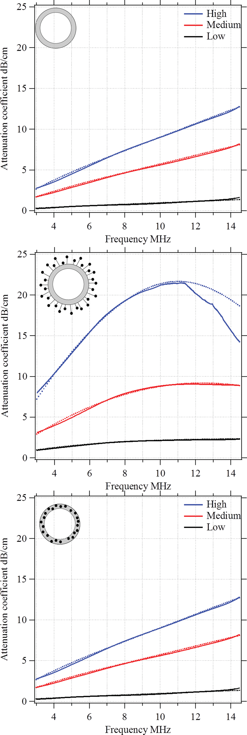 | ||
| Fig. 12 Attenuation coefficient versus frequency for three types of MBs: (a) plain, (b) MBs-chem and (c) MBs-phys, at three different concentrations. Solid lines in each plot indicate the experimental data, while dotted lines show the theoretical predictions according to the modified Church model. | ||
Plain MBs show an almost linear frequency dependency of the attenuation coefficient for all studied concentrations. The incremental growth is about 4 dB cm−1 at 10 MHz and we observe a maximum value of about 12 dB cm−1 for the highest MB concentration. MBs-chem showed a sigmoid-like frequency dependency of the attenuation coefficient, with an incremental growth of about 6 dB cm−1 to 12 dB cm−1 at 10 MHz. The highest absolute value for MBs-chem was about 22 dB cm−1 for the highest MB concentration. In contrast, MBs-phys showed an exponential-growth-like frequency dependency of the attenuation coefficient.
The incremental growth is about 1 dB cm−1 to 2 dB cm−1 at 10 MHz and the MBs-phys lowest absolute value is about 6 dB cm−1. Based on these results, we expect the lowest resonance frequency for MBs-chem and the highest value for the resonance frequency for MBs-phys.
By using a mathematical description, which not only considers the size distribution and density but also the viscoelastic properties of the shell material, we were able to model the MBs' response in the high frequency regime. The acoustic tests are performed in the MHz frequency range where MBs are exposed to a dynamic load. Thus, the viscoelastic material properties should be seen as dynamic or time dependent characteristics.91 In general, the mechanism of the MB oscillation during ultrasound exposure is described by a nonlinear Rayleigh–Plesset-like equation.60,61,92–94 At low incident pressure, typically below 100 kPa, the equation is simplified to the description of a harmonic oscillator (eqn (5)) with a resonance frequency ω0(ω) and a damping factor δ(ω), which depends on the viscoelastic properties of the MB shell. All parameters used in the following equations are explained in Table 2.
 | (5) |
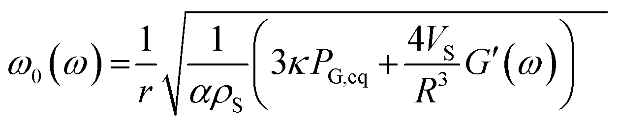 | (6) |
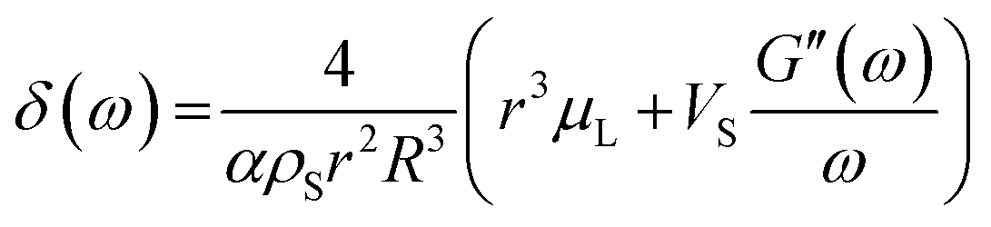 | (7) |
| x | Radial displacement |
| r | Internal shell radius |
| R | External shell radius |
| μ L | Viscosity of the surrounding liquid |
| ρ S | Density of the shell |
| ρ L | Density of surrounding liquid |
| κ | Polytropic exponent of a gas |
| P G,eq | Equilibrium pressure gas in the MB core |
| P ∞(t) | Equilibrium pressure far from the bubble surface |
| G(t) | Relaxation function |
| G′(ω) | Storage modulus |
| G′′(ω) | Loss modulus |
| α | 1 + (ρL − ρS)r/ρSR |
| Vs | R 3 − r3 |
The total loss of energy, including absorption and scattering, from the acoustic wave propagating through the suspension of the MBs can be assessed using the extinction cross-section, σe given in eqn (8).61,92
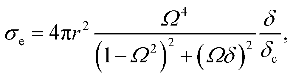 | (8) |
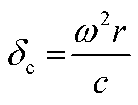 , damping from radiation resistance,61,92
 , damping from viscosity in the embedding liquid60
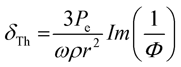 , thermal damping61,92
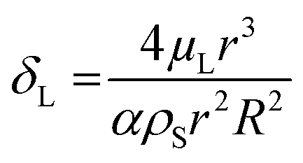
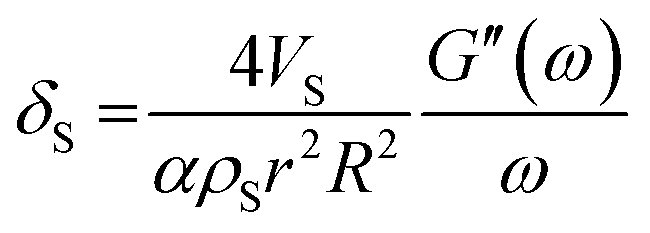 , damping from the shell.47
Two extra terms, namely damping from radiation resistance and thermal damping, are added to the Church model to its original formulation in eqn (7). The attenuation coefficient, α(ω) in dB per unit length, can now be recalculated from the extinction cross-section:
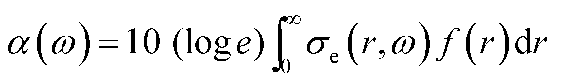 | (9) |
| G′(ω) = Geq + G1ω3/4 | (10) |
| G′′(ω) = ω(μ0 − μ1ω) | (11) |
Additional parameters used for the modelling are the speed of sound in pure water at 24 °C, c = 1493 m s−1; the viscosity of the surrounding liquid, μL = 1 × 10⁻³ Pa s; the density of the surrounding liquid ρL = 1000 kg m−3; and the atmospheric pressure P0 = 105 Pa.
With the above-described modified Church model that accommodates the frequency dependence of the dynamic viscoelastic module, we were able to fit the experimental data of the frequency-dependent attenuation coefficient. Dotted lines in Fig. 12 demonstrate the results of the theoretical modelling for each type of MB.
The main idea of the fitting procedure is the variation of four coefficients: the storage G′(ω) and loss modulus G′′(ω), the resonance frequency, and the damping of the harmonic oscillator. As a result, the extinction cross-section σe for each bubble will alter. Taking into account the distribution and concentration of the bubbles in a suspension one obtains the attenuation profile with respect to the driving frequency. Based on the diameter and shell thickness that were determined in the MBs' structural characterization in the first part of this paper, we were able to reconstruct the viscoelastic modulus of the shell. In Table 3, the four coefficients are indicated, which were used to determine the storage G′(ω) and loss modulus G′′(ω). A comparison between the two magnetic MBs shows that lower values for the static terms of both viscoelastic moduli, Geq and μ0, were observed for MBs-chem. In addition, MBs-chem have a lower resonance frequency of about 10 MHz than MBs-phys which have a resonance frequency of about 25 MHz. From these results, we conclude that MBs-chem are less rigid, are driven easier to oscillation, and are more echogenic than MBs-phys. Thus, the trend observed for the mechanical shell properties in the high-frequency regime and the acoustic tests are in agreement with the shells' mechanical properties measured in the low-frequency regime. For both frequency regimes, MBs-chem showed a significant lower stiffness than MBs-phys.
| Type of MBs | Plain | MBs-chem | MBs-phys | ||
|---|---|---|---|---|---|
| c, 106 MB mL−1 | 0.2; 0.9; 1.8 | 0.4 | 0.9 | 2 | 0.5; 1; 2 |
| G eq, MPa | 10.5 | 4.0 | 3.8 | 4.0 | 28.0 |
| G 1, Pa (rad−1 s−1)3/4 | 5.5 | 10.7 | 4.2 | 0.1 | 10.0 |
| μ 0, Pa s | 0.6 | 0.3 | 0.2 | 0.2 | 0.7 |
| μ 1, 10−9 Pa s2 per rad | 3.2 | 0.01 | 0.9 | 2.0 | 2.0 |
| F resonance, MHz | 12–14 | 11–16 | 10–12 | 9–10 | 18–20 |
4. Conclusions
In this interdisciplinary work, we presented strategies for a rational design of multimodality contrast agents. In particular, we provided a quantitative characterization of polymeric US/MRI contrast agents and their mechanical properties in the low- and high-frequency regime. The presented hybrid probes were produced using two different manufacturing processes leading to structurally different types of magnetic MBs. In the first process, a one-pot synthesis, SPIONs were physically embedded inside the polymeric network of the PVA shell (MBs-phys). In the second process, a two-step synthesis, SPIONs were covalently attached to the shell surface (MBs-chem). Both SPION integration methods did not alter the diameter or the shell thickness of the magnetic MBs compared to plain MBs. However, we observed significant differences in the mechanical properties of the polymeric shell. The elastic modulus of MBs-chem, studied using quasi-static force measurements, was reduced from 1.3 MPa (plain MBs) to 0.23 MPa (MBs-chem). For plain MBs, the polymeric shell is stabilized by chemical and physical cross-links within the PVA network. Through the chemical treatment physical cross-links are lost, which leads to softening of the shell. In particular, crystalline domains in the PVA shell that serve as physical cross-links were lost by the postproduction treatment as demonstrated by DSC measurements. For MBs-phys that contain SPIONs embedded inside the polymer shell, we observed a reinforcement of the PVA shell. This is reflected in an increase of the elastic modulus from 1.3 MPa (plain MBs) to 3.2 MPa (MBs-phys). Further acoustic experiments showed that the mechanical properties characterized in the quasi-static deformation experiments (AFM) set the trend for the MB behaviour during ultrasound exposure. In the acoustic experiments, the frequency-dependency of the attenuation coefficient was analyzed with Church's modified model, which not only considers the size distribution and density but also the viscoelastic properties of the shell material. Thus, we were able to reconstruct the dynamic viscoelastic modulus of the PVA shell. The trend of the results is in agreement with the AFM experiments and provided evidence that the shell of MBs-chem is characterized by a much softer shell compared to MBs-phys. Thus, we can conclude that shell properties analyzed on the single particle level were crucial to understand the more complex behaviour of an ensemble of MBs exposed to an acoustic field. In summary, the presented work contributes to understand basic structure–property relations relevant for the performance of UCAs and provides a fundamental approach for the sustainable design and optimization of US/MRI contrast agents.Acknowledgements
M.P. thanks Dr. habil Lars Dähne and Dr. Gabriella Egri from Surflay Nanotec GmbH, Berlin, for fruitful discussions and helpful criticism on the characterization of MB dimensions. M.P. and R.H. thank Carmen Kunert for her help with the sample preparation and acquisition of TEM images. C.K. appreciates discussions with Dr. Wolfgang Häfner. The authors want to acknowledge the financial support from the European Commission within the 7th framework program of the FP7 Project 245572 3MICRON-Three modality contrast imaging using multi-functionalized microballoons.Notes and references
- J. R. Lindner, Nat. Rev. Drug Discovery, 2004, 3, 527–532 CrossRef CAS PubMed.
- T. F. Massoud and S. S. Gambhir, Genes Dev., 2003, 17, 545–580 CrossRef CAS PubMed.
- R. Weissleder, Science, 2006, 312, 1168–1171 CrossRef CAS PubMed.
- M. A. Pysz, S. S. Gambhir and J. K. Willmann, Clin. Radiol., 2010, 65, 500–516 CrossRef CAS PubMed.
- S. R. Cherry, Semin. Nucl. Med., 2009, 39, 348–353 CrossRef PubMed.
- M. S. Judenhofer, H. F. Wehrl, D. F. Newport, C. Catana, S. B. Siegel, M. Becker, A. Thielscher, M. Kneilling, M. P. Lichy, M. Eichner, K. Klingel, G. Reischl, S. Widmaier, M. Rocken, R. E. Nutt, H.-J. Machulla, K. Uludag, S. R. Cherry, C. D. Claussen and B. J. Pichler, Nat. Med., 2008, 14, 459–465 CrossRef CAS PubMed.
- T. Beyer, D. W. Townsend, T. Brun, P. E. Kinahan, M. Charron, R. Roddy, J. Jerin, J. Young, L. Byars and R. Nutt, J. Nucl. Med., 2000, 41, 1369–1379 CAS.
- H. Hricak, B. I. Choi, A. M. Scott, K. Sugimura, A. Muellner, G. K. von Schulthess, M. F. Reiser, M. M. Graham, N. R. Dunnick and S. M. Larson, Radiology, 2010, 257, 498–506 CrossRef PubMed.
- A. Cuocolo and É. Breatnach, Eur. J. Nucl. Med. Mol. Imaging, 2009, 37, 163–167 CrossRef PubMed.
- A. Y. Louie, Chem. Rev., 2009, 110, 3146–3195 CrossRef PubMed.
- L. Curiel, R. Chopra and K. Hynyne, IEEE Trans. Med. Imaging, 2007, 26, 1740–1746 CrossRef PubMed.
- D. A. Feinberg, D. Giese, D. A. Bongers, S. Ramanna, M. Zaitsev, M. Markl and M. Gunther, Magn. Reson. Med., 2010, 63, 290–296 CrossRef PubMed.
- C. Chandrana, P. Bevan, J. Hudson, I. Pang, P. Burns, D. Plewes and R. Chopra, Phys. Med. Biol., 2011, 56, 861–877 CrossRef PubMed.
- H. Mehrabian, C. Chandrana, I. Pang, R. Chopra and A. L. Martel, Eur. Radiol., 2012, 22, 1735–1747 CrossRef PubMed.
- M. Claudon, D. Cosgrove, T. Albrecht, L. Bolondi, M. Bosio, F. Calliada, J. M. Correas, K. Darge, C. Dietrich, M. D'Onofrio, D. H. Evans, C. Filice, L. Greiner, K. Jager, N. de Jong, E. Leen, R. Lencioni, D. Lindsell, A. Martegani, S. Meairs, C. Nolsoe, F. Piscaglia, P. Ricci, G. Seidel, B. Skjoldbye, L. Solbiati, L. Thorelius, F. Tranquart, H. P. Weskott and T. Whittingham, Ultraschall Med., 2008, 29, 28–44 CrossRef CAS PubMed.
- F. Piscaglia, C. Nolsoe, C. F. Dietrich, D. O. Cosgrove, O. H. Gilja, M. Bachmann Nielsen, T. Albrecht, L. Barozzi, M. Bertolotto, O. Catalano, M. Claudon, D. A. Clevert, J. M. Correas, M. D'Onofrio, F. M. Drudi, J. Eyding, M. Giovannini, M. Hocke, A. Ignee, E. M. Jung, A. S. Klauser, N. Lassau, E. Leen, G. Mathis, A. Saftoiu, G. Seidel, P. S. Sidhu, G. t. Haar, D. Timmerman and H. P. Weskott, Ultraschall Med., 2012, 33, 33–59 CrossRef CAS PubMed.
- D. Cosgrove and C. Harvey, Med. Biol. Eng. Comput., 2009, 47, 813–826 Search PubMed.
- J. Kim, Y. Piao and T. Hyeon, Chem. Soc. Rev., 2009, 38, 372–390 RSC.
- Y.-X. Wang, S. Hussain and G. Krestin, Eur. Radiol., 2001, 11, 2319–2331 CrossRef CAS PubMed.
- B. Bonnemain, J. Drug Targeting, 1998, 6, 167–174 CrossRef CAS PubMed.
- M. A. Malvindi, A. Greco, F. Conversano, A. Figuerola, M. Corti, M. Bonora, A. Lascialfari, H. A. Doumari, M. Moscardini, R. Cingolani, G. Gigli, S. Casciaro, T. Pellegrino and A. Ragusa, Adv. Funct. Mater., 2011, 21, 2548–2555 CrossRef CAS.
- Z. Liu, T. Lammers, J. Ehling, S. Fokong, J. Bornemann, F. Kiessling and J. Gatjens, Biomaterials, 2011, 32, 6155–6163 CrossRef CAS PubMed.
- T. B. Brismar, D. Grishenkov, B. Gustafsson, J. Harmark, A. Barrefelt, S. V. V. N. Kothapalli, S. Margheritelli, L. Oddo, K. Caidahl, H. Hebert and G. Paradossi, Biomacromolecules, 2012, 13, 1390–1399 CrossRef CAS PubMed.
- A. M. Chow, K. W. Y. Chan, J. S. Cheung and E. X. Wu, Magn. Reson. Med., 2010, 63, 224–229 CAS.
- R. Lu, B. Xu, K. Tao, H. J. Dou, Y. Y. Qiu, K. Sun, Y. Q. Zhang, L. P. Wu and K. Sun, Colloid Polym. Sci., 2012, 290, 63–71 CAS.
- F. Yang, Y. X. Li, Z. P. Chen, Y. Zhang, J. R. Wu and N. Gu, Biomaterials, 2009, 30, 3882–3890 CrossRef CAS PubMed.
- E. G. Schutt, D. H. Klein, R. M. Mattrey and J. G. Riess, Angew. Chem., Int. Ed., 2003, 42, 3218–3235 CrossRef CAS PubMed.
- N. de Jong, A. Bouakaz and P. Frinking, Echocardiography: J. Cardiovasc. Ultrasound. Allied Tech., 2002, 19, 229–240 Search PubMed.
- R. R. Qiao, C. H. Yang and M. Y. Gao, J. Mater. Chem., 2009, 19, 6274–6293 RSC.
- B. S. Zolnik, À. González-Fernández, N. Sadrieh and M. A. Dobrovolskaia, Endocrinology, 2010, 151, 458–465 CrossRef CAS PubMed.
- P. Baluk, A. Hirata, G. Thurston, T. Fujiwara, C. R. Neal, C. C. Michel and D. M. McDonald, Am. J. Physiol.: Lung Cell. Mol. Physiol., 1997, 272, L155–L170 CAS.
- S. T. Reddy, A. J. van der Vlies, E. Simeoni, V. Angeli, G. J. Randolph, C. P. O'Neil, L. K. Lee, M. A. Swartz and J. A. Hubbell, Nat. Biotechnol., 2007, 25, 1159–1164 CrossRef CAS PubMed.
- M. P. Desai, V. Labhasetwar, G. L. Amidon and R. J. Levy, Pharm. Res., 1996, 13, 1838–1845 CrossRef CAS.
- J. D. Lathia, L. Leodore and M. A. Wheatley, Ultrasonics, 2004, 42, 763–768 CrossRef CAS PubMed.
- E. Stride and M. Edirisinghe, Soft Matter, 2008, 4, 2350–2359 RSC.
- K. Ferrara, R. Pollard and M. Borden, Annu. Rev. Biomed. Eng., 2007, 9, 415–447 CrossRef CAS PubMed.
- S. Feinstein, B. Coll, D. Staub, D. Adam, A. Schinkel, F. ten Cate and K. Thomenius, J. Nucl. Cardiol., 2010, 17, 106–115 CrossRef PubMed.
- X. W. Cai, F. Yang and N. Gu, Theranostics, 2012, 2, 103–112 CrossRef CAS PubMed.
- F. Yang, Y. Li, Z. Chen, Y. Zhang, J. Wu and N. Gu, Biomaterials, 2009, 30, 3882–3890 CrossRef CAS PubMed.
- J. I. Park, D. Jagadeesan, R. Williams, W. Oakden, S. Chung, G. J. Stanisz and E. Kumacheva, ACS Nano, 2010, 4, 6579–6586 CrossRef CAS PubMed.
- M. Postema and G. Schmitz, Ultrason. Sonochem., 2007, 14, 438–444 CrossRef CAS PubMed.
- F. Cavalieri, A. El Hamassi, E. Chiessi and G. Paradossi, Langmuir, 2005, 21, 8758–8764 CrossRef CAS PubMed.
- WO Pat., PCT/EP2007/006886, 2008.
- WO Pat., PCT/IB2009/005215, 2009.
- F. Cavalieri, A. El Hamassi, E. Chiessi, G. Paradossi, R. Villa and N. Zaffaroni, Biomacromolecules, 2006, 7, 604–611 CrossRef CAS PubMed.
- D. Grishenkov, L. Kari, L.-A. Brodin, T. B. Brismar and G. Paradossi, Ultrasonics, 2010, 51, 40–48 CrossRef PubMed.
- D. Grishenkov, C. Pecorari, T. B. Brismar and G. Paradossi, Ultrasound Med. Biol., 2009, 35, 1127–1138 CrossRef PubMed.
- D. Grishenkov, C. Pecorari, T. B. Brismar and G. Paradossi, Ultrasound Med. Biol., 2009, 35, 1139–1147 CrossRef PubMed.
- C. Pecorari and D. Grishenkov, J. Acoust. Soc. Am., 2007, 122, 2425–2430 CrossRef CAS PubMed.
- G. Paradossi, P. Pellegretti and A. Trucco, Ultrasound contrast agents – Targeting and processing methods for theranostics, Springer, 2010 Search PubMed.
- B. Cerroni, E. Chiessi, S. Margheritelli, L. Oddo and G. Paradossi, Biomacromolecules, 2011, 12, 593–601 CrossRef CAS PubMed.
- DE Pat., 10 2011 000 264.2–43, 2011.
- E. Glynos, V. Koutsos, W. N. McDicken, C. M. Moran, S. D. Pye, J. A. Ross and V. Sboros, Langmuir, 2009, 25, 7514–7522 CrossRef CAS PubMed.
- E. Glynos, V. Sboros and V. Koutsos, Mater. Sci. Eng., B, 2009, 165, 231–234 CrossRef CAS.
- V. Sboros, E. Glynos, S. D. Pye, C. M. Moran, M. Butler, J. Ross, R. Short, W. N. McDicken and V. Koutsos, Ultrasound Med. Biol., 2006, 32, 579–585 CrossRef CAS PubMed.
- V. Sboros, E. Glynos, S. D. Pye, C. M. Moran, M. Butler, J. A. Ross, W. N. McDicken and V. Koutsos, Ultrasonics, 2007, 46, 349–354 CrossRef CAS PubMed.
- E. Buchner Santos, J. K. Morris, E. Glynos, V. Sboros and V. Koutsos, Langmuir, 2012, 28, 5753–5760 CrossRef CAS PubMed.
- C. A. Grant, J. E. McKendry and S. D. Evans, Soft Matter, 2012, 8, 1321–1326 RSC.
- J. E. McKendry, C. A. Grant, B. R. G. Johnson, P. L. Coletta, J. A. Evans and S. D. Evans, Bubble Sci., Eng., Technol., 2010, 2, 48–54 CrossRef CAS.
- C. C. Church, J. Acoust. Soc. Am., 1995, 97, 1510–1521 CrossRef.
- L. Hoff, P. C. Sontum and J. M. Hovem, J. Acoust. Soc. Am., 2000, 107, 2272–2280 CrossRef PubMed.
- C. A. Schneider, W. S. Rasband and K. W. Eliceiri, Nat. Methods, 2012, 9, 671–675 CrossRef CAS PubMed.
- J. L. Hutter and J. Bechhoefer, Rev. Sci. Instrum., 1993, 64, 1868–1873 CrossRef CAS.
- W. A. Ducker, T. J. Senden and R. M. Pashley, Nature, 1991, 353, 239–241 CrossRef CAS.
- P. A. L. Fernandes, G. Tzvetkov, R. H. Fink, G. Paradossi and A. Fery, Langmuir, 2008, 24, 13677–13682 CrossRef CAS PubMed.
- B. Graf-Zeiler, R. H. Fink and G. Tzvetkov, ChemPhysChem, 2011, 12, 3503–3509 CrossRef CAS PubMed.
- G. Tzvetkov, P. Fernandes, S. Wenzel, A. Fery, G. Paradossi and R. H. Fink, Phys. Chem. Chem. Phys., 2009, 11, 1098–1104 RSC.
- G. Tzvetkov, B. Graf, P. Fernandes, A. Fery, F. Cavalieri, G. Paradossi and R. H. Fink, Soft Matter, 2008, 4, 510–514 RSC.
- G. Tzvetkov, G. Paradossi, M. Tortora, P. Fernandes, A. Fery, B. Graf-Zeiler and R. H. Fink, Mater. Sci. Eng., C, 2010, 30, 412–416 CrossRef CAS.
- F. Cavalieri, I. Finelli, M. Tortora, P. Mozetic, E. Chiessi, F. Polizio, T. B. Brismar and G. Paradossi, Chem. Mater., 2008, 20, 3254–3258 CrossRef CAS.
- A. E. Smith, Z. Zhang and C. R. Thomas, Chem. Eng. Sci., 2000, 55, 2031–2041 CrossRef CAS.
- F. Dubreuil, N. Elsner and A. Fery, Eur. Phys. J. E, 2003, 12, 215–221 CrossRef CAS PubMed.
- A. Fery, F. Dubreuil and H. Mohwald, New J. Phys., 2004, 6, 13 CrossRef.
- M. Pretzl, M. Neubauer, M. Tekaat, C. Kunert, C. Kuttner, G. Leon, D. Berthier, P. Erni, L. Ouali and A. Fery, ACS Appl. Mater. Interfaces, 2012, 4, 2940–2948 CAS.
- N. Elsner, F. Dubreuil, R. Weinkamer, F. D. Fischer, F. Wasicek and A. Fery, Prog. Colloid Polym. Sci., 2006, 132, 117–132 CAS.
- A. Fery and R. Weinkamer, Polymer, 2007, 48, 7221–7235 CrossRef CAS.
- E. Reissner, J. Math. Phys., 1946, 25, 80–85 CrossRef.
- E. Reissner, J. Math. Phys., 1946, 25, 279–300 CrossRef.
- M. Krumova, D. López, R. Benavente, C. Mijangos and J. M. Pereña, Polymer, 2000, 41, 9265–9272 CrossRef CAS.
- C. M. Hassan and N. A. Peppas, Macromolecules, 2000, 33, 2472–2479 CrossRef CAS.
- J. M. Morancho, J. M. Salla, A. Cadenato, X. Fernández-Francos, P. Colomer, Y. Calventus, X. Ramis and R. Ruíz, J. Appl. Polym. Sci., 2012, 124, E57–E65 CrossRef CAS.
- C.-M. Chan, J. Wu, J.-X. Li and Y.-K. Cheung, Polymer, 2002, 43, 2981–2992 CrossRef CAS.
- X.-L. Xie, Q.-X. Liu, R. K.-Y. Li, X.-P. Zhou, Q.-X. Zhang, Z.-Z. Yu and Y.-W. Mai, Polymer, 2004, 45, 6665–6673 CrossRef CAS.
- M. J. Solomon, A. S. Almusallam, K. F. Seefeldt, A. Somwangthanaroj and P. Varadan, Macromolecules, 2001, 34, 1864–1872 CrossRef CAS.
- H. Liu and L. C. Brinson, Compos. Sci. Technol., 2008, 68, 1502–1512 CrossRef CAS.
- J. Liang, Y. Huang, L. Zhang, Y. Wang, Y. Ma, T. Guo and Y. Chen, Adv. Funct. Mater., 2009, 19, 2297–2302 CrossRef CAS.
- Z. Peng, L. X. Kong and S. D. Li, Synth. Met., 2005, 152, 25–28 CrossRef CAS.
- M. F. Bedard, A. Munoz-Javier, R. Mueller, P. del Pino, A. Fery, W. J. Parak, A. G. Skirtach and G. B. Sukhorukov, Soft Matter, 2009, 5, 148–155 RSC.
- F. Dubreuil, D. G. Shchukin, G. B. Sukhorukov and A. Fery, Macromol. Rapid Commun., 2004, 25, 1078–1081 CrossRef CAS.
- A. L. Klibanov, P. T. Rasche, M. S. Hughes, J. K. Wojdyla, K. P. Galen, J. H. Wible and G. H. Brandenburger, Invest. Radiol., 2004, 39, 187–195 CrossRef PubMed.
- J. D. Ferry, Viscoelastic Properties of Polymers, Wiley, New York, 3rd edn, 1980 Search PubMed.
- L. Hoff, Acoustic Characterization of Contrast Agents for Medical Ultrasound Imaging, Kluwer Academic Publishers, 2002 Search PubMed.
- L. Rayleigh, Philos. Mag. 6, 1917, 34, 94–98 CrossRef.
- M. S. Plesset, Journal of Applied Mechanics-Transactions of the Asme, 1949, 16, 277–282 Search PubMed.
Footnote |
| † Electronic supplementary information (ESI) available. See DOI: 10.1039/c3sm51560e |
| This journal is © The Royal Society of Chemistry 2014 |