
 Open Access Article
 This Open Access Article is licensed under a
 Creative Commons Attribution 3.0 Unported Licence
Controlling charge separation in a novel donor–acceptor metal–organic framework via redox modulation†
C. F.
Leong
,
B.
Chan
,
T. B.
Faust
and
D. M.
D'Alessandro
*
School of Chemistry, The University of Sydney, New South Wales 2006, Australia. E-mail: deanna.dalessandro@sydney.edu.au
First published on 4th August 2014
Abstract
Charge transfer metal–organic frameworks represent a versatile class of multifunctional materials that offer an unprecedented combination of physical properties. The framework [(Zn(DMF))2(TTFTC)(DPNI)] incorporating the donor and acceptor, tetrathiafulvalenetetracarboxylate (TTFTC) and N,N′-di-(4-pyridyl)-1,4,5,8-naphthalenetetracarboxydiimide (DPNI) respectively, exhibits charge transfer by virtue of donor–acceptor interactions within its crystalline structure. This through-space interaction is manifested by the formation of ligand-based radicals in the as-synthesised material and leads to a partial degree of charge separation. Five distinct electronic states of the framework can be accessed using solid state electrochemical and spectroelectrochemical techniques, including for the first time in application to metal–organic frameworks, EPR spectroelectrochemistry (SEC). The degree of charge transfer is controllable via redox modulation and has been quantified using complementary DFT modelling of the charge transfer states.
A Introduction
The incorporation of redox-active moieties into metal–organic frameworks (MOFs) is of growing interest owing to the plethora of potential applications for these materials as microporous conductors, molecular sensors1 and light harvestors.2 Due to the periodic arrangement of electroactive metals and ligands within MOFs, they provide ideal systems in which to study fundamental aspects of charge migration in three-dimensional coordination space.Judicious selection of metal ions and organic ligands enables a degree of control over local interactions and thus the functional properties of a framework. This has led to the development of materials with interesting redox behaviours, charge transfer (CT)3 and energy transfer interactions2a brought about by the intrinsic electronic properties and relative spatial arrangements of the electroactive species. In addition to π–π stacking and through-bond charge delocalisation, phenomena ranging from the transfer of partial charge from electron donor (D) to acceptor (A) units,3,4 to exciton migration in photoactive systems2a have been observed in MOFs.
The potential of radicals to engage in CT interactions represents a particularly significant and widespread phenomenon that has been intensively studied since the first report of an ‘organic metal,’ tetrathiafulvalene-tetracyanoquinodimethane (TTF-TCNQ) in 1973.5a In addition to the metallic conductivity displayed by this material, CT salts are known to possess tunable electronic characteristics, whereby the degree of CT is controllable via modulation of the ionisation potential and electron affinity of the donor and acceptor, respectively.5b
In contrast to organic CT salts, charge transfer in coordination solids has been investigated to a limited extent.3,4 The increased dimensionality and structural robustness of MOFs may facilitate a greater level of control over the arrangement of electroactive components, as well as allowing for more in depth analyses of CT phenomena. The intrinsic microporosity of MOFs also represents a key structural feature that may pave the way towards tunable CT via host–guest interactions. By these means, the possibility of developing multifunctional D–A systems exhibiting enhanced stability and tunability for a wide range of electronic applications may be realised.
Herein we report a redox-active D–A MOF, [(Zn(DMF))2(TTFTC)(DPNI)] (TTFTC = tetrathiafulvalenetetracarboxylate and DPNI = N,N′-di-(4-pyridyl)-1,4,5,8-naphthalenetetracarboxydiimide), which incorporates the D and A, TTF and naphthalene diimide (NDI) units respectively, which are organised in a mixed-stack. This type of arrangement has been known to result in a small degree of CT in various organic materials by virtue of the close stacking of D–A moieties (approximately 3.5 Å in mixed-stack systems).6 The transfer of partial charge from D to A dispersed throughout the framework was probed using a complementary suite of solid state techniques including solid state electrochemistry, UV-Vis-NIR and Raman spectroscopy, as well as EPR spectroelectrochemistry (SEC). The porosity of the framework was also investigated to assess its future potential for guest-dependent behaviour. Unlike organic CT materials which are typically unstable to redox modulation, the [(Zn(DMF))2(TTFTC)(DPNI)] framework enables an electrochemical approach to interrogating CT phenomena which, to the best of our knowledge, has not previously been undertaken for MOFs.
B Results and discussion
The framework [(Zn(DMF))2(TTFTC)(DPNI)] was synthesised solvothermally by heating a mixture of Zn(NO3)2·6H2O, H4TTFTC and DPNI in DMF at 80 °C for 48 hours to yield dichroic green-yellow prismatic crystals. The crystal structure was solved and refined in the monoclinic space group P21/c with unit cell of parameters a = 8.3800(4), b = 20.9662(9), c = 13.0999(6) Å and β = 95.038(3)°. The asymmetric unit consists of one crystallographically unique Zn2+ ion in a tetrahedral coordination geometry bound to half a TTFTC and DPNI ligand through a η1-O and a pyridyl-N, respectively, in addition to one DMF molecule. A single unbound DMF molecule was refined at half occupancy due to positional disorder. Packing of these moieties results in a diamondoid topology (Fig. 1a) with substantial π–π stacking of TTFTC and DPNI ligands in a herringbone arrangement in the order ⋯DADADA⋯ along the a-direction at distances of 3.561 Å, which is in the range for mixed-stack materials of a neutral or slightly ionic nature (Fig. 1b).6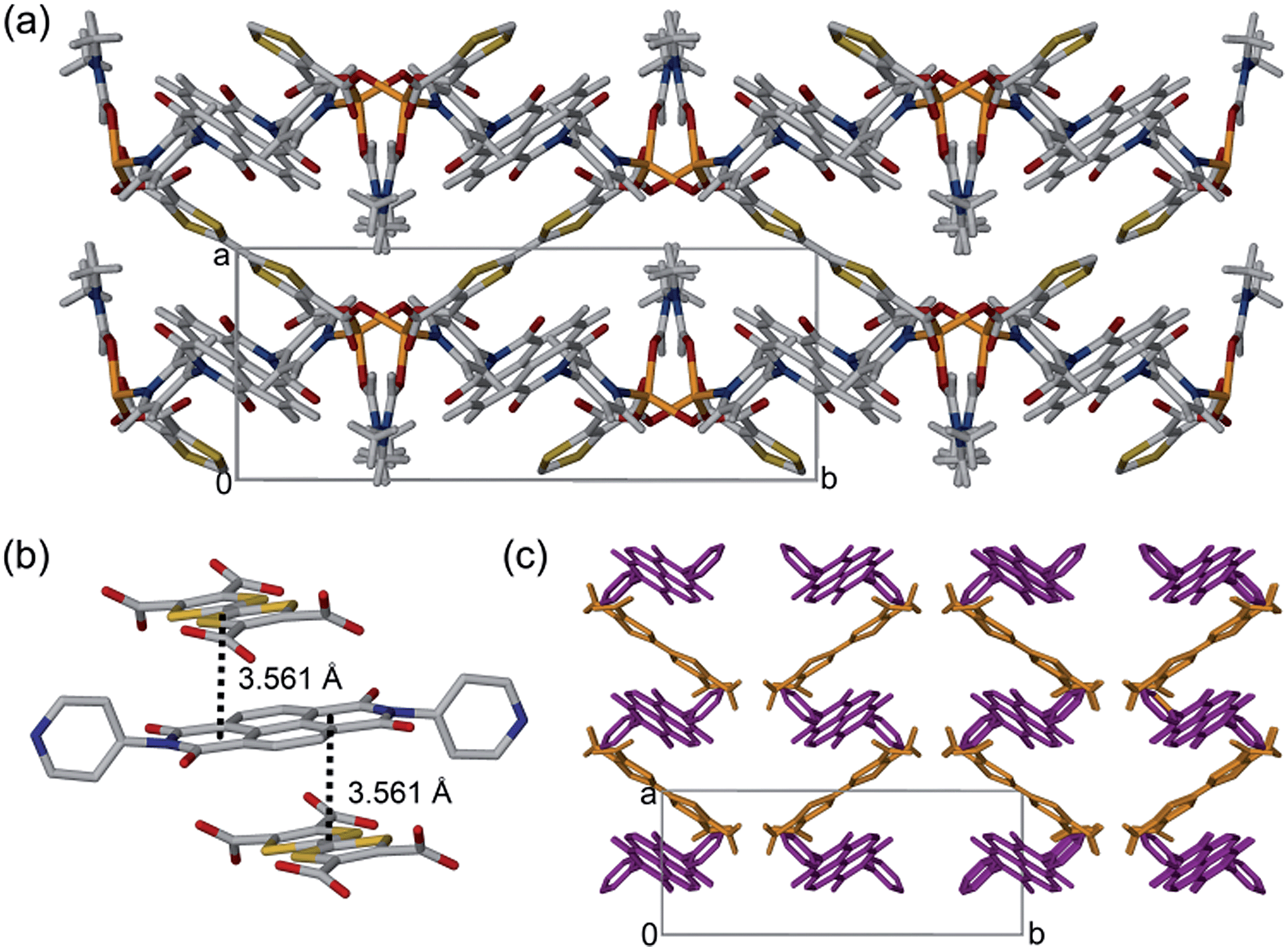 | ||
| Fig. 1 (a) Crystal structure of [(Zn(DMF))2(TTFTC)(DPNI)] viewed down the c-axis. (b) Stacking of the TTFTC and DPNI ligands in the order ⋯DADADA⋯ at distances of 3.561 Å. Colour scheme: C, grey; O, red; N, blue; S, yellow; Zn, orange. (c) Stacking of TTFTC (orange) and DPNI (purple) ligands in [(Zn(DMF))2(TTFTC)(DPNI)] arranged in a herringbone pattern. Hydrogen atoms and solvent excluded for clarity. | ||
The free DMF molecules occupy the diamondoid channels along the crystallographic c-axis and hydrogen bond relatively strongly to the carbonyl functionalities of both DPNI and TTFTC at distances in the range 2.7–3.3 Å. The TTF and NDI cores are stacked orthogonally and are displaced such that, considering a single D–A stack, only one ring of the TTF core directly faces the NDI core. The length of the central C![[double bond, length as m-dash]](https://www.rsc.org/images/entities/char_e001.gif) C bond of TTFTC is 1.338(9) Å, which suggests that the TTF unit is in its neutral oxidation state.7 This information is seemingly contradictory to the case of CT, however, it is important to note that this is a crystallographic average and the framework is likely to be accommodating a small degree of CT which is dispersed heterogeneously throughout the material. Subsequent measurements discussed in this report were performed on bulk microcrystalline powder (Fig. S1, ESI†). Gas adsorption experiments on [(Zn(DMF))2(TTFTC)(DPNI)] revealed that the material exhibits a small degree of porosity in the ultramicroporous regime (Fig. S2, ESI†). The BET surface area was determined as 22 m2 g−1 from an 77 K N2 adsorption isotherm, while the CO2 adsorption and desorption isotherms at 195 K revealed a small uptake of 0.38 mmol g−1 at 0.9 bar, with significant hysteresis due to trapping of CO2 molecules in the small pores.
C bond of TTFTC is 1.338(9) Å, which suggests that the TTF unit is in its neutral oxidation state.7 This information is seemingly contradictory to the case of CT, however, it is important to note that this is a crystallographic average and the framework is likely to be accommodating a small degree of CT which is dispersed heterogeneously throughout the material. Subsequent measurements discussed in this report were performed on bulk microcrystalline powder (Fig. S1, ESI†). Gas adsorption experiments on [(Zn(DMF))2(TTFTC)(DPNI)] revealed that the material exhibits a small degree of porosity in the ultramicroporous regime (Fig. S2, ESI†). The BET surface area was determined as 22 m2 g−1 from an 77 K N2 adsorption isotherm, while the CO2 adsorption and desorption isotherms at 195 K revealed a small uptake of 0.38 mmol g−1 at 0.9 bar, with significant hysteresis due to trapping of CO2 molecules in the small pores.
Considering the solid state UV-Vis-NIR spectrum of [(Zn(DMF))2(TTFTC)(DPNI) and its neutral and radical ligand components, a new absorption band was observed at 12![[thin space (1/6-em)]](https://www.rsc.org/images/entities/char_2009.gif) 400 cm−1 (Fig. 2) in the spectrum of the framework which was assigned to CT between the TTFTC and DPNI ligand cores. The broad band in the range 16500–23000 cm−1 in the framework spectrum can be attributed to a mixture of neutral and radical ligand bands, which is consistent with the assignment of partial CT heterogeneously scattered throughout the framework leading to co-existing neutral and radical states. The nature of this newfound band was elucidated with TD-DFT computations at the BMK/6-31G(d) level. Thus, we have compared the calculated electronic excitation spectrum for the (TTFTC)(DPNI) complex with those computed for H4TTFTC and DPNI. The general features of these calculated spectra are consistent with those in Fig. 2, with a moderately intense low-energy band in the spectrum of the framework that is not found in the spectra of H4TTFTC and DPNI. Our computations have led to the assignment of this new band in the framework to the HOMO–LUMO transition, with the HOMO located largely on the TTFTC unit, while the LUMO is associated mainly with the DPNI moiety.
400 cm−1 (Fig. 2) in the spectrum of the framework which was assigned to CT between the TTFTC and DPNI ligand cores. The broad band in the range 16500–23000 cm−1 in the framework spectrum can be attributed to a mixture of neutral and radical ligand bands, which is consistent with the assignment of partial CT heterogeneously scattered throughout the framework leading to co-existing neutral and radical states. The nature of this newfound band was elucidated with TD-DFT computations at the BMK/6-31G(d) level. Thus, we have compared the calculated electronic excitation spectrum for the (TTFTC)(DPNI) complex with those computed for H4TTFTC and DPNI. The general features of these calculated spectra are consistent with those in Fig. 2, with a moderately intense low-energy band in the spectrum of the framework that is not found in the spectra of H4TTFTC and DPNI. Our computations have led to the assignment of this new band in the framework to the HOMO–LUMO transition, with the HOMO located largely on the TTFTC unit, while the LUMO is associated mainly with the DPNI moiety.
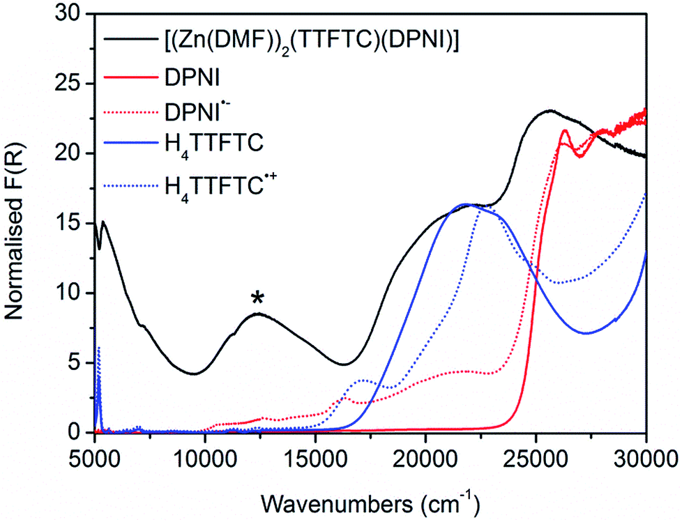 | ||
| Fig. 2 Solid state UV-Vis-NIR spectra of [(Zn(DMF))2(TTFTC)(DPNI)] (black), DPNI (solid red), DPNI radical anion (dashed red), H4TTFTC (solid blue), H4TTFTC radical cation (dashed blue). The new band assigned to CT in [(Zn(DMF))2(TTFTC)(DPNI)] is indicated by an asterisk. | ||
The EPR response of [(Zn(DMF))2(TTFTC)(DPNI)] (black line of Fig. 3c) provides further evidence of the presence of CT in the framework. Fitting of the EPR profile requires the inclusion of two radical species to accommodate for the splitting in the signal, which is further suggestive of CT in [(Zn(DMF))2(TTFTC)(DPNI)], leading to the coexistence of both the TTFTC radical cation and DPNI radical anion. Indeed, our Mulliken charge analysis using DFT at the BMK/6-31G(d) level shows a partial charge transfer (δ) from TTFTC to DPNI of δ = 0.6 for the (TTFTC)(DPNI) complex. In this case, the TTFTC unit carries a charge of −3.4 (TTFTC carries an overall charge of −4, hence upon charge transfer of 0.6, a new charge of −3.4 is achieved), while the remaining charge of −0.6 resides on DPNI. Despite this reasonably large value of δ, it must be reinforced that CT is likely to be heterogeneously dispersed throughout the framework. On inspection of the EPR spectrum, the dominance of the TTFTC radical cation relative to that of the DPNI radical anion is apparent. Previous studies have shown that in the presence of a proton source, TTF is capable of undergoing oxidation to its radical cation state.8,9 It is likely that the deprotonation of the tetraacid, H4TTFTC, in the reaction mixture during synthesis acted as an external driving force for self-oxidation, resulting in a higher concentration of the TTFTC radical cation in the as-synthesised framework compared to the DPNI radical anion, which was exclusively generated through CT.
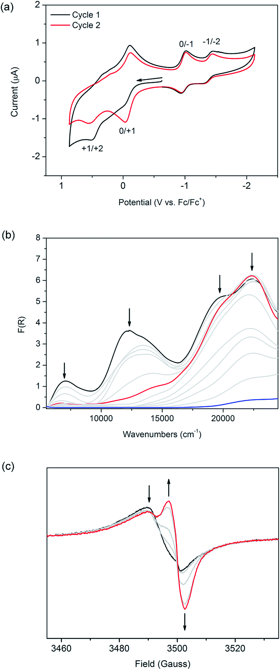 | ||
| Fig. 3 (a) Solid state CV of [(Zn(DMF))2(TTFTC)(DPNI)] at 100 mV s−1 in a 0.1 M n-Bu4NPF6/CH3CN electrolyte. The black line is the first cycle and the red line is the second cycle, after framework decomposition has occurred. Arrow indicates direction of forward scan. (b) Solid state Vis-NIR SEC of [(Zn(DMF))2(TTFTC)(DPNI)] at 0 V (black), −0.75 V (red) and −1.00 V (blue). Grey lines show the spectral transition. (c) Solid state EPR SEC of [(Zn(DMF))2(TTFTC)(DPNI)] at 0 V (black) and −0.80 V (red) in 0.1 M n-Bu4NPF6/CH3CN. Grey lines show the spectral transition and the arrows show the direction of the spectral change. | ||
Raman spectroscopy was employed to probe changes in the vibrational frequencies accompanying redox state changes in the ligand cores. The spectrum of [(Zn(DMF))2(TTFTC)(DPNI)] exhibits one peak at 1413 cm−1 and two peaks at 1525 and 1606 cm−1 (Fig. S5 in ESI†). By comparison with our computed spectra for TTFTC and the TTFTC radical cation obtained at the BMK/6-31G(d) level, the peak at 1413 cm−1 is assigned to stretching of the central CC bond in TTFTC. The peaks at 1525 and 1606 cm−1 are assigned to the symmetrical and antisymmetrical stretching modes of the outer CC bonds in the TTF unit which are coupled to the central CC stretch. Such assignments are consistent with previous studies.10 Interestingly, the DFT spectra suggest that the peak at 1413 cm−1 is more characteristic of the TTFTC radical cation, while the peaks at 1525 and 1606 cm−1 show a stronger resemblance to neutral TTFTC. Comparison of the calculated spectra for the TTFTC radical cation, TTFTC, DPNI, the DPNI radical anion and DMF, has led to the attribution of the sharp peak at 1726 cm−1 to carbonyl stretching in the partially reduced DPNI, while the sharp signal at 498 cm−1 is assigned to ring breathing in TTFTC.10a The energies of these stretching modes suggest the presence of both neutral and radical species within the framework, which is further indicative of a partial CT between TTFTC and DPNI.
The cyclic voltammogram of [(Zn(DMF))2(TTFTC)(DPNI)] exhibits two broad redox processes in the anodic region at E1/2 = −0.070 and 0.37 vs. Fc/Fc+ on the first cycle which corresponds to the oxidation of neutral TTFTC to its radical cation state followed by further oxidation to its dicationic form (black line in Fig. 3a), as elucidated from solution state electrochemistry of H4TTFTC (Fig. S6 in ESI†). Upon a second cycle (red line in Fig. 3a), the peak current associated with the first oxidation step increases significantly, suggesting that a fraction of the TTFTC ligands already exist in their radical cation state in the as-synthesised material. As a result, oxidation of residual TTFTC to its radical cation state occurs during the first sweep. The CT interaction in the framework can thus be electrochemically “switched off” by cycling the potential, which has the effect of “resetting” the redox state. Our calculated potentials for molecular TTFTC at the M06-2X/6-311 + G(3d, 2p) level are −0.84 and 0.07 V, respectively, for the first and second oxidation processes. The corresponding values calculated for H4TTFTC are 0.42 and 1.34 V. Thus, the experimentally determined potentials of −0.022 and 0.51 V fall within the ranges spanned by TTFTC and its protonated form, H4TTFTC. This is consistent with TTFTC being terminated by Zn2+ within the framework. Interestingly, the measured potential for the first oxidation is closer to the calculated value for H4TTFTC than the calculated value for TTFTC. On the other hand, the second oxidation occurs at a potential that is closer to that for TTFTC than that for H4TTFTC. This can be rationalised by noting that, upon oxidation, the TTFTC moiety becomes less negative which consequently weakens its interaction with Zn2+ and therefore shifts its electronic behaviour towards that of TTFTC rather than H4TTFTC.
In the cathodic region, two reversible reduction processes were observed at E1/2 = −0.98 and −1.40 V for the framework (Fig. 3a), and correspond to the reduction of DPNI to its radical anion and dianion states, respectively (as shown for DPNI itself in Fig. S6, ESI†). This assignment is further supported by our computationally calculated reduction potentials of −1.15 and −1.66 V, respectively, for a DPNI molecule. The calculated potentials for molecular DPNI are slightly more cathodic than the experimental values for the framework. This can be attributed to the coordination of DPNI to Zn2+, which facilitates the uptake of electrons. On the timescale of the cyclic voltammetry experiment, the framework is stable to cycling between its monoradical cation and anion states (Fig. S9, ESI†), however it cannot withstand repeated cycling to higher anodic and cathodic potentials which correspond to formation its dication and dianion states.
The application of solid state Vis-NIR SEC11 shows that the band at 12400 cm−1 decreases in intensity at an applied potential of −0.75 V, in addition to a decrease in intensity of the shoulder at 19500 cm−1, which is a feature of the TTFTC radical cation (Fig. 3b). The disappearance of the CT band is also observed in the comparison between the computed TD-DFT electronic excitation spectra of the (TTFTC)(DPNI) complex and that for the corresponding one-electron reduced species (TTFTC)(DPNI˙−). An inspection of the distribution of the Mulliken charges in (TTFTC)(DPNI˙−) shows a charge of −3.9 for the TTFTC unit and −1.1 for DPNI−, which equates to δ = 0.1. Thus, the reduction process consists of transformation of the partially oxidised TTF unit to its neutral form, together with the reduction of DPNI to its radical anion.12 In other words, CT becomes largely inhibited upon one-electron reduction. Changing the potential to −1.00 V led to framework collapse, as evidenced by the drastic decrease in absorption intensity, reinforcing the observations made from electrochemistry. In scanning anodically, the CT band increases and radical TTFTC bands increase in intensity until decomposition of the framework occurs (Fig. S10 of ESI†). This observation supports the significance of the CT interaction in the as-synthesised material in stabilising the framework structure. The difference in absolute potentials between the various electrochemical and spectroelectrochemical techniques is a result of different cell resistances.
Owing to the EPR activity of as-synthesised [(Zn(DMF))2(TTFTC)(DPNI)], solid state EPR SEC of the framework material served as an invaluable tool to probe its response to an electrochemical bias. To the best of our knowledge, this is the first report on the use of this technique as a means of characterising both charge transfer as well as MOFs. At a potential difference of −0.80 V, the EPR signal at g = 2.0059 decreases while the intensity of the signal at g = 2.0034 increases significantly (Fig. 3c). This corresponds to the decrease in the population of TTFTC radical cations, and an increase in the population of DPNI radical anions upon electrochemical reduction. The incomplete conversion of the TTFTC radical to its neutral species is attributed to residual particles of the microcrystalline solid of [(Zn(DMF))2(TTFTC)(DPNI)] within the SEC cell which were not in contact with the working electrode. Application of a more cathodic potential of −1.00 V results in degradation of the framework, as evidenced by EPR as a 13-line hyperfine spectrum characteristic of DPNI radical cations solubilised in DMF (see Fig. S11 in ESI†), consistent with a previous report by Langford and co-workers.12 This provides further support that the EPR activity of [(Zn(DMF))2(TTFTC)(DPNI)] does indeed originate from contributions of both TTFTC and DPNI in their radical cation and anion states, respectively, brought about by inter-ligand CT.
Conclusions
In summary, the electronic and optical properties of the novel framework [(Zn(DMF))2(TTFTC)(DPNI)] incorporating the redox-active moieties TTF and NDI, were investigated to elucidate the nature of the charge transfer behaviour. Despite the crystallographic data pointing towards a neutral system, the use of a complement of solid state techniques including UV-Vis-NIR, EPR, electrochemistry, Raman spectroscopy, in addition to Vis-NIR SEC and EPR SEC, enabled the presence of partial CT, heterogeneously distributed throughout the framework material, to be characterised. These experimental data are supported by DFT computational calculations. The use of this suite of techniques provides a strong basis for the comprehensive study of D–A and radical MOFs13 which hold great promise in the area of conductive and photoactive materials. Future work involving subtle electronic modifications of both D and A should result in materials exhibiting a continuum of CT behaviour.Acknowledgements
We gratefully acknowledge the support of the Australian Research Council (ARC) for this research and, the ARC and Wellcome Trust for provision of the EPR spectrometer.Notes and references
- (a) Y. Takashima, V. M. Martinez, S. Furukawa, M. Kondo, S. Shimomura, H. Uehara, M. Nakahama, K. Sugimoto and S. Kitagawa, Nat. Commun., 2011, 2, 1 Search PubMed; (b) J. An, C. M. Shade, D. A. Chengelis-Czegan, S. Petoud and N. L. Rosi, J. Am. Chem. Soc., 2011, 133, 1220 CrossRef CAS PubMed.
- (a) C. Y. Lee, O. K. Farha, B. J. Hong, A. A. Sarjeant, S. B. T. Nguyen and J. T. Hupp, J. Am. Chem. Soc., 2011, 133, 15858 CrossRef CAS PubMed; (b) H.-J. Son, S. Jin, S. Patwardhan, S. J. Wezenberg, N. C. Jeong, M. So, C. E. Wilmer, A. A. Sarjeant, G. C. Schatz, R. Q. Snurr, O. K. Farha, G. P. Wiederrecht and J. T. Hupp, J. Am. Chem. Soc., 2012, 135, 862 CrossRef PubMed.
- (a) B. D. McCarthy, E. R. Hontz, S. R. Yost, T. Van Voorhis and M. Dincă, J. Phys. Chem. Lett., 2013, 4, 453 CAS; (b) A. A. Talin, A. Centrone, A. C. Ford, M. E. Foster, V. Stavila, P. Haney, R. Adam Kinney, V. Szalai, F. El Gabaly, H. P. Yoon, F. Léonard and M. D. Allendorf, Science, 2014, 343, 66 CrossRef CAS PubMed.
- (a) H. Miyasaka, Acc. Chem. Res., 2012, 46, 246 Search PubMed; (b) H. Miyasaka, C. S. Campos-Fernández, R. Clérac and K. R. Dunbar, Angew. Chem., Int. Ed., 2000, 39, 3831 CrossRef CAS; (c) X. Zhang, Z. Zhang, H. Zhao, J.-G. Mao and K. R. Dunbar, Chem. Commun., 2014, 50, 1429 RSC.
- (a) J. Ferraris, D. O. Cowan, V. Walatka and J. H. Perlstein, J. Am. Chem. Soc., 1973, 95, 948 CrossRef CAS; (b) K. P. Goetz, D. Vermeulen, M. E. Payne, C. Kloc, L. E. McNeil and O. D. Jurchescu, J. Mater. Chem. C, 2014, 2, 3065 RSC.
- T. J. Kistenmacher, T. J. Emge, A. N. Bloch and D. O. Cowan, Acta Crystallogr., Sect. B: Struct. Crystallogr. Cryst. Chem., 1982, 38, 1193 CrossRef.
- (a) L. Tan, G. Zhang, D. Zhang and D. Zhu, J. Org. Chem., 2011, 76, 9046 CrossRef CAS PubMed; (b) C. U. Pittman, M. Narita and Y. F. Liang, J. Org. Chem., 1976, 41, 2855 CrossRef CAS.
- P.-T. Chiang, N.-C. Chen, C.-C. Lai and S.-H. Chiu, Chem.–Eur. J., 2008, 14, 6546 CrossRef CAS PubMed.
- M. Giffard, P. Alonso, J. Garín, A. Gorgues, T. P. Nguyen, P. Richomme, A. Robert, J. Roncali and S. Uriel, Adv. Mater., 1994, 6, 298 CrossRef CAS PubMed.
- (a) D. Jankowski, R. Świetlik, O. Jeannin, A. Assaf, E. W. Reinheimer and M. Fourmigué, J. Raman Spectrosc., 2013, 44, 1765 CrossRef CAS PubMed; (b) R. Bozio, I. Zanon, A. Girlando and C. Pecile, J. Chem. Phys., 1979, 71, 2282 CrossRef CAS PubMed; (c) J. Olivier, S. Golhen, R. Świetlik, O. Cador, F. Pointillart and L. Ouahab, Eur. J. Inorg. Chem., 2009, 3282 CrossRef CAS PubMed.
- P. M. Usov, C. Fabian and D. M. D'Alessandro, Chem. Commun., 2012, 48, 3945 RSC.
- G. Andric, J. F. Boas, A. M. Bond, G. D. Fallon, K. P. Ghiggino, C. F. Hogan, J. A. Hutchison, M. A. Lee, S. J. Langford, J. R. Pilbrow, G. J. Troup and C. P. Woodward, Aust. J. Chem., 2004, 57, 1011 CrossRef CAS.
- T. B. Faust and D. M. D'Alessandro, RSC Adv., 2014, 4, 17498 RSC.
Footnote |
| † Electronic supplementary information (ESI) available: Detailed experimental and computational methods, tables of crystallographic data (CCDC 997130), results of PXRD, electrochemical, spectroelectrochemical, EPR and Raman measurements. CCDC 997130. For ESI and crystallographic data in CIF or other electronic format see DOI: 10.1039/c4sc01551g |
| This journal is © The Royal Society of Chemistry 2014 |