 Open Access Article
Creative Commons Attribution 3.0 Unported Licence
Improved overall water splitting with barium tantalate mixed oxide composites
Julia
Soldat
a,
Roland
Marschall
*ab and
Michael
Wark
ac
aLaboratory of Industrial Chemistry, Ruhr-University Bochum, Germany. E-mail: Roland.Marschall@phys.chemie.uni-giessen.de; Fax: +49-641-9934509; Tel: +49-641-9934585
bInstitute of Physical Chemistry, Justus-Liebig-University Giessen, Heinrich-Buff-Ring 58, 35392 Giessen, Germany
cInstitute of Technical Chemistry, Carl von Ossietzky University Oldenburg, Germany
First published on 15th July 2014
Abstract
The combination of effective charge carrier separation and improved electron transfer in highly crystalline barium tantalate composites modified with Rh–Cr2O3 core–shell co-catalyst systems induces enhanced activity for overall water splitting (OWS) with stoichiometric amounts of H2 and O2 (2![[thin space (1/6-em)]](https://www.rsc.org/images/entities/char_2009.gif) :
:![[thin space (1/6-em)]](https://www.rsc.org/images/entities/char_2009.gif) 1). A sol–gel route employing complexing reagents was investigated to prepare selectively defined mixed oxide materials with improved surface areas and smaller particle sizes compared to the conventional solid state reaction (SSR). The catalytic activities of the materials are investigated in photocatalytic test reactions for hydrogen production and overall water splitting. The formation of Rh–Cr2O3 core–shell co-catalyst systems for water splitting is evidenced by transmission electron microscopy (TEM) and X-ray Photoelectron Spectroscopy (XPS). Moreover, we developed new and highly active barium tantalate composites for hydrogen generation from aqueous methanol solutions under UV-light, which show the highest hydrogen evolution rate for a three-component composite consisting of Ba5Ta4O15/Ba3Ta5O15/BaTa2O6. Hydrogen rates of more than 6 mmol h−1 can be achieved without any co-catalyst. Using Rh–Cr2O3 core–shell co-catalysts on these three-component composites simultaneous generation of H2 and O2 from pure water splitting reaches rates up to 70% higher than for the pure Ba5Ta4O15.
1). A sol–gel route employing complexing reagents was investigated to prepare selectively defined mixed oxide materials with improved surface areas and smaller particle sizes compared to the conventional solid state reaction (SSR). The catalytic activities of the materials are investigated in photocatalytic test reactions for hydrogen production and overall water splitting. The formation of Rh–Cr2O3 core–shell co-catalyst systems for water splitting is evidenced by transmission electron microscopy (TEM) and X-ray Photoelectron Spectroscopy (XPS). Moreover, we developed new and highly active barium tantalate composites for hydrogen generation from aqueous methanol solutions under UV-light, which show the highest hydrogen evolution rate for a three-component composite consisting of Ba5Ta4O15/Ba3Ta5O15/BaTa2O6. Hydrogen rates of more than 6 mmol h−1 can be achieved without any co-catalyst. Using Rh–Cr2O3 core–shell co-catalysts on these three-component composites simultaneous generation of H2 and O2 from pure water splitting reaches rates up to 70% higher than for the pure Ba5Ta4O15.
1. Introduction
Photocatalysis with semiconductor materials exhibits a very important area of research. In the last decades, especially mixed-oxide photocatalysts with layered perovskite structure were discovered being very active materials for clean hydrogen production and direct water splitting.1–5 In particular (111)-layered materials with the composition A5M4O15 (A = Sr, Ba; M = Ta, Nb) have made remarkable progress under ultra-violet (UV) light.6–9 On the other hand enhanced photocatalytic hydrogen generation has been obtained with composites,10 which include different compounds or phases of classical semiconductor systems, like CdS–TiO2 (ref. 3) or α-/β-Ga2O3.11 The increase in photocatalytic activity is based on an improved charge carrier separation in the composite photocatalyst and reduced electron–hole recombination since the charge carriers are spatially separated on different crystal compounds or phases.However, there are several more parameters which affect the photocatalytic activity and efficiency. The electronic structure, morphology, high crystallinity, but concurrently small particle sizes are important challenges.12 The solid state reaction (SSR) presents still an easy and conventional way to synthesize photocatalyst materials like Ba5Ta4O15.13 However, this method applies high reaction temperatures to the oxide precursors, the particle sizes of the resulting materials are usually in the range of several micrometers. Therefore, the surface areas of the SSR products are very low in the range of only a few m2 g−1. To overcome this problem we applied a sol–gel synthesis using the complexing reagents EDTA (ethylene diamine tetraacetic acid) and citric acid (citrate route)14 for the synthesis of barium tantalate.15 Also several other complex semiconductor materials like CsTaWO6 have been successfully prepared by this method recently.16 One of the key challenges in photocatalysis is overall water splitting (OWS).
| 2H2O → 2H2 + O2 | (1) |
This reaction with semiconductor photocatalysts has been studied extensively as a potential method to supply clean and renewable hydrogen without the need of sacrificial electron donors.17–22 Thus, an effective formation of a Rh–Cr2O3 core–shell co-catalyst structure has been described by Domen and his co-workers for efficient OWS, using it onto GaN-ZnO solid solution catalysts to optimize photocatalytic OWS in visible light.23 This core–shell structure contains an amorphous Cr2O3 shell which is reported to be impermeable for O2 molecules but very well permeable for protons and evolved H2, thus inhibiting the unwanted back reaction of H2 and O2 during light irradiation.23 In another report the use of CuOx species in combination with Cr2O3 as co-catalyst for enabling OWS has been demonstrated on Ga2O3 recently, although no core–shell structure was formed,24 raising questions about the influence of Cr2O3. In the present manuscript, we report for the first time of a Rh–Cr2O3 core–shell co-catalyst system on barium tantalate Ba5Ta4O15 to achieve overall water splitting. More importantly, we describe the formation of multicomponent heterojunction photocatalysts consisting of Ba5Ta4O15, Ba3Ta5O15 and BaTa2O6, leading to highly efficient charge carrier separation. Optimum ratios of those three components result in very high H2 evolution rates from methanol containing solutions even without co-catalysts, and the optimized OWS on those photocatalyst composites using very small amounts of Rh–Cr2O3 core–shell co-catalysts. These investigations lead to optimized materials which are excellent starting materials for future doping and OWS in visible light.
2. Experimental
Synthesis of materials
For the synthesis of Ba5Ta4O15 by the citrate route, 7 g of EDTA (99%, alfa-aesar) and 7.25 g of citric acid (98%, alfa aesar) were dissolved in 570 mL water, the pH was adjusted to 8.3 using conc. ammonia water (33%, J. T. Baker). After dissolution, the pH was set to 5 using conc. nitric acid (J. T. Baker), and 15 mL of hydrogen peroxide were added to stabilize the highest oxidation state of Ta. 10.224 mmol of Ta(OEt)5 (99+%, alfa-aesar) was dissolved in abs. ethanol, and added in small portions to the solution while heating to 90 °C. Finally, a solution of 12.78 mmol Ba(NO3)2 (99.95%, alfa-aesar) was added in small portions to avoid any precipitation and to get the final clear solution. For preparation of barium tantalate composites the barium precursor amount was stepwise decreased from 12.78 mmol to 5.6 mmol Ba(NO3)2. The samples were named according to the amount of Ba(NO3)2 added (e.g. BaTa 12.78 equates to 12.78 mmol Ba precursor); the Ta(OEt)5 amount was always kept constant. In all the syntheses after solvent evaporation a black powder precursor remained which was calcined at 600 °C for 4 hours to evaporate any carbon leaving a white powder as raw product. A second calcination step was performed in a furnace for 10 hours at 1000 °C to induce high crystallinity of the final product.Preparation of Rh–Cr2O3 core–shell co-catalyst
Rh nanoparticles were deposited onto the photocatalyst materials via reductive photodeposition with a specific amount of Na3RhCl6 (99.999%, Aldrich) precursor solution using the setup described below. Further photodeposition of Cr2O3 was performed from sequential amounts of K2CrO4 (99.9%, Wako Pure Chemicals) precursor solution by a stepwise in situ photodeposition25 to find the optimum loading of Cr2O3.Characterization
X-ray powder diffraction measurements were carried out to characterize the phase compositions of the precursors and the calcined samples. Diffraction patterns were recorded in reflection geometry with an Empyrean Theta-Theta diffractometer (Panalytical, Almelo) equipped with a copper tube, 0.25° divergent slit, 0.5° antiscatter slit (incident beam), 7.5 mm high antiscatter slit (diffracted beam), incident and diffracted beam 0.04 rad soller slits, and a position sensitive PIXcel-1d detector. The Cu K-beta emission line is suppressed by a Ni filter. For qualitative phase analysis the specimens were scanned in the 10–75° 2θ range with a step width of 0.0131° and 250 s collection time at an ambient temperature of 300 K. The ICDD powder diffraction file (PDF2) in conjunction with the HighScore Plus software (Panalytical, Almelo) was used for qualitative phase analysis. Transmission electron microscopy (TEM) images of selected samples were measured with an H-7100 electron microscope (100 kV) from Hitachi. BET surface areas were obtained using Kr gas with a Quantachrome Autosorb-1-MP. UV-Vis diffuse reflectance spectra were measured using a Perkin Elmer Lambda 650 UV-Vis spectrometer equipped with a Praying-Mantis mirror construction. The obtained spectra were converted by the Kubelka–Munk function F(R) into absorption spectra, using MgO nanopowder as a white standard. Optical band gaps (Eg) were obtained via Tauc-plots, a method invented by the physicist Jan Tauc,26 using the calculation α = A(hν − Eg)n/hν, where α is the absorption coefficient, A is a constant, hν is the energy of light, and n = 2 stands for materials with indirect transition, respectively.27–31 Assuming the absorption coefficient α being proportional to the Kubelka–Munk function F(R), the Eg can be obtained from the plot of [F(R)hν]1/nversus hν, by extrapolation of the linear part near the onset of the absorption edge to intersect the energy axis.Photocatalytic reactions
Photocatalytic hydrogen generation was measured in a home-made air free closed gas system using an inner irradiation-type quartz reactor with water cooling jacket. As a light source, a 700 W Hg mid-pressure immersion lamp (Peschl UV-Consulting, set to a power of 500 W) was used for irradiation and cooled with a double-walled quartz mantle using a thermostat (LAUDA). Gas evolution was detected online using a multi-channel analyzer (Emerson) equipped with a detector for the determination of the concentration of hydrogen (thermal conductivity detector), oxygen (paramagnetism) and carbon dioxide (IR). Argon was used as carrier gas; the continuous gas flow was controlled by a Brockhorst mass flow controller. The gas flow was set to 50 NmL min−1 (normal flow throughput: gas flow at normal temperature and pressure per minute). All reactions were performed at 13 °C.For reactions in presence of methanol as electron donor, 500 mg of photocatalyst were suspended in 550 mL water and 50 mL methanol (electron donor). To get a homogeneous suspension a treatment in the ultrasonication bath for 10 minutes at 30 °C was performed. Before any photocatalytic reaction was initiated, the whole system including the photocatalyst was flushed with argon at 100 NmL min−1 for 30 minutes to remove any trace of air.
Before adding the Na3RhCl6 or K2CrO4 solution for photodeposition, the light irradiation was stopped, and the precursor solutions were added with a syringe through a rubber seal without opening the reactor. Traces of air were subsequently removed by flushing the reactor again with Argon before starting light irradiation. Upon light irradiation, metallic Rh is deposited onto the photocatalyst surface sites preferentially accessible for electrons, while CO2 is formed from methanol as also detected with our gas analyzer. Cr2O3 is only deposited onto Rh nanoparticles. Gas evolution measurements were continued to investigate the hydrogen generation properties with Rh–Cr2O3 providing active sites for hydrogen evolution while using the residual methanol as sacrificial agent. Measurements were repeated several times, the error is below 30 μmol h−1. For OWS, the samples after sequential photodeposition were filtered, washed extensively with distilled water and dried overnight, before using them in pure water for stoichiometric H2 and O2 evolution.
3. Results and discussion
Characterization
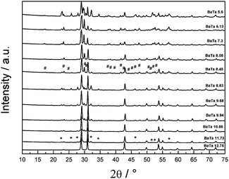
Fig. 1 shows the diffraction patterns of Ba5Ta4O15 and its synthesized barium tantalates composites calcined for 10 h at 1000 °C. Ba5Ta4O15 has a (111)-layered perovskite structure constructed of corner-sharing TaO6 octahedra. The structure can be regarded as a simple perovskite structure being cut along the [110] and [111] directions into slabs which are separated by Ba2+ cations.32The XRD pattern of the barium tantalate material synthesized via citrate route according to literature15 shows the pure Ba5Ta4O15 crystal structure, in very good agreement with the standard diffraction pattern of Ba5Ta4O15 (JCPDS 18-0193/JCPDS 72-0631); all reflections can be indexed accordingly. The BET surface of the pure phase SSR product exhibits more than three times lower surface area compared to the citrate product (1.2 m2 g−1vs. 4.0 m2 g−1).15 When the total amount of barium nitrate precursor in the synthesis was slightly decreased to 11.73 mmol, a small amount of a second material can be observed which was identified as Ba3Ta5O15 (indicated by stars in Fig. 2) in agreement with its standard diffraction pattern (JCPDS 83-0713). Ba3Ta5O15 exhibits a tetragonal structure with space group P4/mbm.15,33
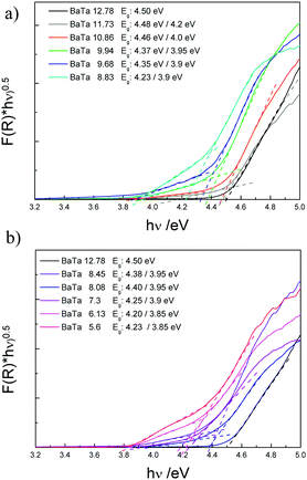 | ||
| Fig. 2 Tauc plots of Ba5Ta4O15 (BaTa 12.78) and its two-component composites (a) and three-component composites (b) via diffuse reflectance UV-Vis absorption spectroscopy. | ||
After a stepwise decrease of the Ba2+ precursor concentration down to 8.45 mmol a third compound is observed which can be identified as BaTa2O6 (reflections indicated by rhombs). It is well known that BaTa2O6 crystallizes in three different temperature dependent modifications: below 1150 °C a modification isostructural with orthorhombic BaNb2O6 is formed, between 1150 °C and 1300 °C a tetragonal tungsten bronze type structure is apparent, and above this temperature the hexagonal structure occurs.34
Due to the calcination temperature of only 1000 °C and the analysis by XRD technique the third component can be indexed as the orthorhombic form of BaTa2O6 (JCPDS 20-0146). All determined reflections are sharp which indicates a good crystallinity of the materials after citrate route synthesis and calcination. A further decrease in the barium precursor concentration to less than 6 mmol leads to additional reflections in the XRD (BaTa 5.6), which could not be identified yet.
The different barium tantalate multicomponent composite materials were further investigated by UV-Vis absorption spectroscopy. Fig. 2 shows the Tauc plots of the pure phase material Ba5Ta4O15 compared to the two material composites (a) and the composites containing three components (b).
For Ba5Ta4O15 (BaTa 12.78) a band gap of 4.5 eV is obtained which is in agreement with our previously published results.15 The two-component heterojunctions consisting of Ba5Ta4O15 and Ba3Ta5O15 show a different absorption behavior compared to pure Ba5Ta4O15. The main absorption edges related to the absorption of Ba5Ta4O15 in the two-component composites are slightly shifted towards higher wavelengths, which might be attributed to the existence of the second material Ba3Ta5O15. Additionally a small shoulder can be observed for each of these two-component composites. This shoulder might correspond to the Ba3Ta5O15 material in the composite photocatalysts. Therefore, two different band gaps can be estimated from the Tauc plots, in which the absorption shoulder related to Ba3Ta5O15 becomes even more evident. With decreased barium content in the samples the band gaps are shifted stepwise from 4.48/4.2 eV towards lower energies of 4.23/3.9 eV. This also represents the variation in the phase composition of the systems. In case of the three-component heterojunction only two different band gaps are estimated, indicating the Ba5Ta4O15 component gradually disappearing with simultaneous development of the third component orthorhombic BaTa2O6 in the same absorption range. BaTa 6.13 shows one band gap of 4.2 eV, which is in good agreement with literature for orthorhombic BaTa2O6 phase (4.1 eV).35 An additional band gap can be identified with a value of 3.85 eV, illustrating still the presence of Ba3Ta5O15. Although we were not able to synthesize Ba3Ta5O15 in pure yet, the rough estimation from the current absorption spectra gives an indication about its band gap.15 The different compositions, estimated band gaps and measured surface areas are summarized in Table 1. All the presented composite materials exhibit surface areas in the same range, thus indicating that the surface area might be a negligible factor when discussing the photocatalytic activities. However, three-component composites seem to have lower surface areas (2.44–3.2 m2 g−1) than two-component composites.
| Sample code | Crystal structures formed | Band gap/eV | S BET/m2 g−1 |
|---|---|---|---|
| BaTa 12.78 | Ba5Ta4O15 | 4.5 | 4 |
| BaTa 11.73 | Ba5Ta4O15/Ba3Ta5O15 | 4.48/4.2 | 3.87 |
| BaTa 10.86 | Ba5Ta4O15/Ba3Ta5O15 | 4.46/4.0 | 4.45 |
| BaTa 9.94 | Ba5Ta4O15/Ba3Ta5O15 | 4.37/3.95 | 5.48 |
| BaTa 9.68 | Ba5Ta4O15/Ba3Ta5O15 | 4.35/3.9 | 3.83 |
| BaTa 8.83 | Ba5Ta4O15/Ba3Ta5O15 | 4.23/3.9 | 5.14 |
| BaTa 8.45 | Ba5Ta4O15/Ba3Ta5O15/BaTa2O6 | 4.38/3.95 | 2.52 |
| BaTa 8.08 | Ba5Ta4O15/Ba3Ta5O15/BaTa2O6 | 4.40/3.95 | 2.54 |
| BaTa 7.3 | Ba5Ta4O15/Ba3Ta5O15/BaTa2O6 | 4.25/3.9 | 2.44 |
| BaTa 6.13 | Ba5Ta4O15/Ba3Ta5O15/BaTa2O6 | 4.2/3.85 | 3.2 |
| BaTa 5.6 | Unknown | 4.23/3.85 | 2.93 |
Photocatalytic results
Hydrogen generation from water with and without methanol was chosen as the main photocatalytic reaction for the reactivity evaluation since (111)-layered barium tantalates are known as very active photocatalysts for water splitting.6 Previous measurements have shown that the optimum loading of co-catalyst for barium tantalate is only 0.0125 wt% of Rh,15 which is much smaller than any reported co-catalyst loadings for any (111) layered perovskites so far (≥0.1 wt%).9The materials are initially tested without any co-catalyst in water containing ∼10 vol% MeOH. Pure Ba5Ta4O15 (BaTa 12.78) is active without any deposited co-catalyst as shown in Fig. 3 (∼1.8 mmol h−1), demonstrating that active surface sites for hydrogen generation are already available on the catalyst surface. After Rh deposition, a hydrogen rate of 4.2 mmol h−1 is detected from H2O/MeOH. The addition of Cr salt solution leads to a drastic decrease in H2 evolution. Using CrO42− as precursor, Cr2O3 was deposited sequentially in steps of 0.00625 wt%, resulting in a final effective loading of 0.025 wt% Cr2O3. This suggests the successful deposition of Cr onto Rh particles. For each reduction of Cr(VI) to Cr(III) three electrons must be available which cannot react to form H2 (eqn (2)). During the deposition the Cr2O3 layer becomes thicker which results in a more complicate transport of electrons for hydrogen generation.
| 2CrO42−(aq) + 10H+(aq) + 6e− → Cr2O3(s) + 5H2O(l) | (2) |
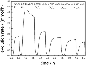 | ||
| Fig. 3 Stepwise photodeposition of Cr2O3 after deposition of specified amount of Rh (0.0125 wt%) in H2O/MeOH onto Ba5Ta4O15. | ||
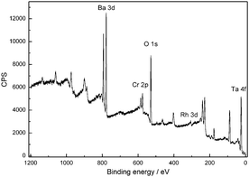
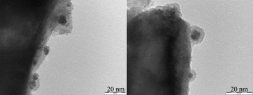
The resulting core–shell structures after stepwise Rh deposition and Cr2O3 loading are characterized by TEM and X-ray Photoelectron Spectroscopy (XPS). In Fig. 4 the XPS spectrum confirms the successful formation of metallic Rh and Cr2O3 in the oxidation state (III). Fig. 5 presents TEM images of Ba5Ta4O15 loaded with 1.125 wt% Rh and 1.187 wt%; Cr2O3, which were prepared to better visualize the core–shell nature of our co-catalysts. Moreover, these amounts are in the range of typical loadings reported earlier.36 The primary particle size of the Rh nanoparticles is in a range of 3–5 nm, although some of them aggregate to form larger secondary particles. These single Rh particles have been coated with a shell layer to form the whole core–shell structure on the catalyst surface. Interestingly the Cr2O3 shell shows always constant thickness of about 2–3 nm which was also already reported by Domen and his co-workers.17
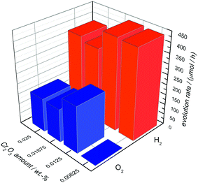
In Fig. 6 the OWS results are shown for 0.0125 wt% Rh-loaded Ba5Ta4O15 with different amounts of deposited Cr2O3. A content of 0.00625 wt% Cr2O3 leads to no O2 generation but shows an H2 rate of 441 μmol h−1 in pure water, suggesting that the back reaction to H2O is not successfully suppressed due to the low amount of Cr2O3.
The most active catalyst can be achieved with only 0.0125 wt% of Cr2O3. Pure water is split into H2 (446 μmol h−1) and O2 (229 μmol h−1) in the nearly optimum stoichiometric ratio. With further Cr2O3 addition the H2 and O2 rates decrease significantly to 358 μmol h−1 and 163 μmol h−1, suggesting that Cr2O3 added in excess acts as inhibitor. Taking the above results of Ba5Ta4O15 into account, we used 0.0125 wt% Cr2O3 for the deposition of Rh–Cr2O3 core–shell co-catalysts onto the composite materials as well as shown below.
Multicomponent photocatalysts
An overview for the H2 evolution rates including all barium tantalate multicomponent composites is shown in Fig. 7. All materials are active for H2 generation from H2O/MeOH solutions without any co-catalyst on the surface (squares), however show different activities depending on the composition, as will be discussed later. The deposition of 0.0125 wt% Rh leads to different behaviors in the composites. On pure Ba5Ta4O15 (BaTa 12.78), the effect of increased activity in presence of Rh is far more pronounced than on the multicomponent composite catalysts BaTa 11.73 to BaTa 5.6. For BaTa 12.78 upon Rh deposition the H2 evolution increases from 1.8 up to 4 mmol h−1. After a strong decrease for BaTa 11.73, an increase in H2 evolution for BaTa 10.86 of nearly 150% was detected without co-catalyst, suggesting an optimum ratio of phase coexistence and surface junctions for this two-component heterojunction.15 In the BaTa 9.94 to BaTa 9.68 region the rate rapidly decreases again, suggesting a loss of sufficient surface junctions. The ratio of components leads apparently to a reduction of possible interfaces and to a decreased electron transfer, as was observed recently for calcium tantalate composite photocatalysts.37 Below BaTa 8.83 BaTa2O6 arises as third material as seen from the XRD patterns in Fig. 1. Down to BaTa 6.13 an extraordinary increase in H2 evolution (up to 6.2 mmol h−1) by over 300% could be obtained. The in situ formation of a Ba5Ta4O15, Ba3Ta5O15 and BaTa2O6 three-component heterojunction obviously leads to reduced charge carrier recombination by spatial separation, with possibly also optimized interface junctions.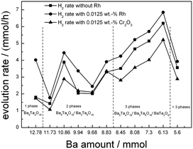 | ||
| Fig. 7 Screening measurements in H2O/MeOH before and after deposition of a specified amount of Rh (0.0125 wt%) as well as stepwise photodeposition of Cr2O3 on BaTa composites. | ||
A further reduction of barium concentration (BaTa 5.6) in the synthesis shows a dramatic decrease in activity, due to a lower content of Ba5Ta4O15 and Ba3Ta5O15 and the transition to the single BaTa2O6 material, which was also reported before as a less active material in water splitting compared to Ba5Ta4O15.1 Furthermore, additional reflexes in the XRD pattern of BaTa 5.6 were observed which could not be identified yet.
From all these results, the role of composite materials becomes more and more evident. We have roughly calculated band positions of Ba5Ta4O15, Ba3Ta5O15 and BaTa2O6 according to a simple procedure proposed by Butler and Ginley,38 where the estimated band gaps from UV-Vis spectroscopy are used. A possible mechanism for charge transfer is shown in Fig. 8. The conduction band of Ba3Ta5O15 is located at a more positive potential compared to the conduction band of Ba5Ta4O15. Thus, photoexcited electrons can be transferred from the conduction band of Ba5Ta4O15 to Ba3Ta5O15 for charge separation, and the recombination with the valence band holes in Ba5Ta4O15 would be reduced.
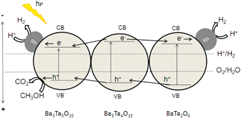 | ||
| Fig. 8 Calculated band positions of Ba3Ta5O15/Ba5Ta4O15/BaTa2O6 (procedure by Butler and Ginley).38 | ||
This effect can explain the improved photocatalytic activity of the barium tantalate two-component composites compared to the pure Ba5Ta4O15. In comparison, the same mechanism is suggested for the three-component heterojunction BaTa 6.13 in which BaTa2O6 has also a lower conduction band level than Ba5Ta4O15. This results in an equal probability for electrons to be transferred after photoexcitation either to Ba3Ta5O15 or BaTa2O6 and for Rh photodeposition onto Ba3Ta5O15 or BaTa2O6 in the composite, and for a vectorial hole transfer in the three component composite. It is also the reason for a different vectorial charge transfer inside the three-component heterojunction compared to two-component composites or pure Ba5Ta4O15. BaTa 6.13 evolves only 11% more H2 after Rh deposition (6.85 mmol h−1) than without co-catalyst, in contrast to Ba5Ta4O15 which generates with 0.0125 wt% Rh 120% more H2 (up to 4 mmol h−1). This trend can be explained due to the stronger driving force for electrons transferred from the conduction band of Ba5Ta4O15 to reduce Rh3+ to form Rh on the single-component photocatalyst.
Moreover, in the presence of a multicomponent heterojunction with three barium tantalate crystal structures with optimum ratio (BaTa 6.13), charge carrier separation on different components seems to be more effective than charge carrier extraction by co-catalyst photodeposition onto single-component Ba5Ta4O15 for H2 generation. BaTa 6.13 generates 6.2 mmol h−1 H2 without any co-catalyst, while pure Ba5Ta4O15 evolves only 4 mmol h−1 of H2 with 0.0125 wt% Rh, which is more than 35% less. This is a clear indication that the formation of intrinsic multicomponent heterojunction photocatalysts is very important as a novel strategy for charge carrier separation without noble metal or other co-catalysts, strongly enhancing photocatalytic activities.10,15,36
To reveal the OWS in the next step we deposited 0.0125 wt% of Cr2O3 on the composite materials (Fig. 7, triangles). Thereby deposition of Cr2O3 species leads to a reduced H2 evolution as shown for Ba5Ta4O15, indicating a successful Cr2O3 deposition on Rh taking place. Fig. 9 demonstrates the H2 and O2 rates for all barium tantalate composites in pure water with 0.0125 wt% Rh and 0.0125 wt% Cr2O3. The diagram indicates that all composite photocatalysts are able to generate both gases simultaneously. As mentioned before, the Rh deposition in water containing ∼10% MeOH solution shows a higher efficiency for BaTa12.78 than for the composites. Thus, we propose the preferred co-catalyst deposition in case of Rh on the main component Ba5Ta4O15. Nevertheless, Fig. 9 exhibits an enhanced OWS for samples synthesized with less than 8.45 mmol Ba2+ precursor compared to the pure Ba5Ta4O15 (Fig. 6). Especially the most active composite BaTa 6.13 consisting of three components yields in an increase up to 650 μmol h−1 H2 and 348 μmol h−1 O2. After further reducing the barium amount the rates rapidly decrease again which is similar to the trend in H2O/MeOH solution. This distinguishes obviously a significant reduction of interfaces in the system which directly leads to a decrease of electron transfer and charge separation. Among those newly prepared barium tantalate composites BaTa 10.86 and BaTa 8.83 as two-component materials and particularly BaTa 6.13 as a three-component heterojunction photocatalyst show remarkable photocatalytic activity in hydrogen production from H2O/MeOH solutions without any co-catalyst as well as with Rh–Cr2O3 in overall water splitting.
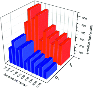 | ||
| Fig. 9 Overall water splitting with barium tantalate composites with 0.0125 wt% Rh and 0.0125 wt% Cr2O3. | ||
4. Conclusions
New types of barium tantalate composite photocatalysts prepared via sol–gel citrate route showed excellent activities in photocatalytic hydrogen generation and overall water splitting, higher than a phase-pure Ba5Ta4O15 material. The improved activity of the composite is assumed to originate from improved charge carrier separation after light absorption in the composite photocatalysts. All presented materials and composites generate hydrogen without co-catalyst. The best three component heterojunction Ba5Ta4O15/Ba3Ta5O15/BaTa2O6 (BaTa 6.13) evolves hydrogen with rates up to 6.2 mmol h−1 compared to the pure Ba5Ta4O15 (1.8 mmol h−1) without any co-catalyst, and up to 6.85 mmol h−1 after photodeposition of Rh. The formation of a core–shell co-catalyst system consisting of very low amounts of Rh–Cr2O3 exhibits stable rates in overall water splitting up to 650 μmol h−1 H2 and 348 μmol h−1 O2 from pure water.Acknowledgements
We thank Dr Harun Tueysuez and Tobias Grewe (MPI for Coal Research, Mülheim, Germany) for TEM measurements, Dr Thomas Reinecke (Faculty of Geosciences, Ruhr-University Bochum) for XRD measurements, Noushin Arshadi, Dr Ilya Sinev, Dr G. Wilma Busser and Prof. Martin Muhler (all Laboratory of Industrial Chemistry, Ruhr-University Bochum) for adsorption measurements, XPS measurements, assistance in photocatalytic measurements and general support, respectively. Financial support by the German Science Foundation (DFG) under WA 1116 and MA 5392 is gratefully acknowledged.Notes and references
- F. E. Osterloh, Chem. Mater., 2007, 20, 35 CrossRef.
- A. Kudo and Y. Miseki, Chem. Soc. Rev., 2009, 38, 253 RSC.
- X. Chen, S. Shen, L. Guo and S. S. Mao, Chem. Rev., 2010, 110, 6503 CrossRef CAS PubMed.
- W. Y. Teoh, J. A. Scott and R. Amal, J. Phys. Chem. Lett., 2012, 3, 629 CrossRef CAS.
- P. D. Tran, L. H. Wong, J. Barber and J. S. C. Loo, Energy Environ. Sci., 2012, 5, 5902 CAS.
- H. Otsuka, K. Kim, A. Kouzu, I. Takimoto, H. Fujimori, Y. Sakata, H. Imamura, T. Matsumoto and K. Toda, Chem. Lett., 2005, 34, 822 CrossRef CAS.
- Y. Miseki, H. Kato and A. Kudo, Chem. Lett., 2006, 35, 1052 CrossRef CAS.
- K. Yoshioka, V. Petrykin, M. Kakihana, H. Kato and A. Kudo, J. Catal., 2005, 232, 102 CrossRef CAS PubMed.
- Y. Miseki, H. Kato and A. Kudo, Energy Environ. Sci., 2009, 2, 306 CAS.
- R. Marschall, Adv. Funct. Mater., 2014, 24, 2421 CrossRef CAS.
- X. Wang, Q. Xu, M. Li, S. Shen, X. Wang, Y. Wang, Z. Feng, J. Shi, H. Han and C. Li, Angew. Chem., Int. Ed., 2012, 51, 13089 CrossRef CAS PubMed.
- H. Tüysüz and F. Schüth, in Advances in Catalysis, ed. C. G. Bruce and C. J. Friederike, Academic Press, 2012, p. 127 Search PubMed.
- F. Galasso and L. Katz, Acta Crystallogr., 1961, 14, 647 CrossRef CAS.
- (a) J. Martynczuk, M. Arnold, H. Wang, J. Caro and A. Feldhoff, Adv. Mater., 2007, 19, 2134 CrossRef CAS; (b) A. Feldhoff, J. Martynczuk and H. Wang, Prog. Solid State Chem., 2007, 35, 339 CrossRef CAS PubMed.
- R. Marschall, J. Soldat, G. W. Busser and M. Wark, Photochem. Photobiol. Sci., 2013, 12, 671 CAS.
- L. Schwertmann, M. Wark and R. Marschall, RSC Adv., 2013, 3(41), 18908 RSC.
- (a) K. Maeda, K. Teramura, D. Lu, N. Saito, Y. Inoue and K. Domen, Angew. Chem., 2006, 118, 7970 CrossRef; (b) K. Maeda, K. Teramura, D. Lu, N. Saito, Y. Inoue and K. Domen, Angew. Chem., Int. Ed., 2006, 45, 7806 CrossRef CAS PubMed.
- K. Maeda, K. Teramura, D. Lu, N. Saito, Y. Inoue and K. Domen, J. Phys. Chem. C, 2007, 111, 7554 CAS.
- K. Maeda and K. Domen, J. Phys. Chem. C, 2007, 111, 7851 CAS.
- N. Sakamoto, H. Ohtsuka, T. Ikeda, K. Maeda, D. Lu, M. Kanehara, K. Teramura, T. Teranishi and K. Domen, Nanoscale, 2009, 1, 106 RSC.
- K. Maeda, A. Xiong, T. Yoshinaga, T. Ikeda, N. Sakamoto, T. Hisatomi, M. Takashima, D. Lu, M. Kanehara, T. Setoyama, T. Teranishi and K. Domen, Angew. Chem., 2010, 122, 4190 ( Angew. Chem., Int. Ed. , 2010 , 49 , 4096 ) CrossRef.
- K. Maeda, N. Sakamoto, T. Ikeda, H. Ohtsuka, A. Xiong, D. Lu, M. Kanehara, T. Teranishi and K. Domen, Chem.–Eur. J., 2010, 16, 7750 CrossRef CAS PubMed.
- K. Maeda, D. Lu, K. Teramura and K. Domen, Energy Environ. Sci., 2010, 3, 470 Search PubMed.
- G. W. Busser, B. Mei, A. Pougin, J. Strunk, R. Gutkowski, W. Schuhmann, M.-G. Willinger, R. Schlögl and M. Muhler, ChemSusChem, 2014, 7, 1030 CrossRef CAS PubMed.
- G. W. Busser, B. Mei and M. Muhler, ChemSusChem, 2012, 5(11), 2200 CrossRef CAS PubMed.
- J. Tauc, Mater. Res. Bull., 1968, 3, 37 CrossRef CAS.
- Y. Izumi, T. Itoi, S. Peng, K. Oka and Y. Shibata, J. Phys. Chem. C, 2009, 113, 6706 CAS.
- R. A. Van Leeuwen, C.-J. Hung, D. R. Kammler and J. A. Switzer, J. Phys. Chem., 1995, 99, 15247 CrossRef CAS.
- Y. Zhang, G. H. Li, Y. C. Wu, Y. Y. Luo and L. Zhang, J. Phys. Chem. B, 2005, 109, 5478 CrossRef CAS PubMed.
- L. Bi and J. Y. Feng, J. Lumin., 2006, 121, 95 CrossRef CAS PubMed.
- I. Bannat, K. Wessels, T. Oekermann, J. Rathousky, D. W. Bahnemann and M. Wark, Chem. Mater., 2009, 21, 1645 CrossRef CAS.
- A. Mukherji, C. Sun, S. C. Smith, G. Q. Lu and L. Wang, J. Phys. Chem. C, 2011, 115, 15674 CAS.
- C. R. Feger and R. P. Ziebarth, Chem. Mater., 1995, 7, 373 CrossRef CAS.
- T. A. Vanderah, R. S. Roth, T. Siegrist, W. Febo, J. M. Loezos and W. Wong-Ng, Solid State Sci., 2003, 5(1), 149 CrossRef CAS.
- H. Kato and A. Kudo, Chem. Phys. Lett., 1998, 295, 487 CrossRef CAS.
- K. Maeda, K. Teramura, N. Saito, Y. Inoue and K. Domen, J. Catal., 2006, 243, 303 CrossRef CAS PubMed.
- P. Wang, P. Chen, A. Kostka, R. Marschall and M. Wark, Chem. Mater., 2013, 25, 4739 CrossRef CAS.
- M. A. Butler and D. S. Ginley, J. Electrochem. Soc., 1978, 125, 228 CrossRef CAS PubMed.
| This journal is © The Royal Society of Chemistry 2014 |

