
Fabrication and characterization of electrospinning/3D printing bone tissue engineering scaffold
Yinxian Yua,
Sha Huab,
Mengkai Yanga,
Zeze Fua,
Songsong Tenga,
Kerun Niua,
Qinghua Zhao*a and
Chengqing Yi*a
aDepartment of Orthopaedic Surgery, Shanghai General Hospital, Shanghai Jiao Tong University School of Medicine, Shanghai, 200080, China. E-mail: ycq5000@163.com; sawboneszhao@163.com
bDepartment of Cardiovascular Medicine, Ruijin Hospital Luwan Branch of Shanghai Jiao Tong University School of Medicine, Shanghai, 200080, China
First published on 9th November 2016
Abstract
Electrospinning and three-dimensional (3D) printing is widely used to fabricate bone tissue engineering scaffolds. However, cells are difficult to infiltrate into the nanoporous structure of traditional electrospun scaffolds by electrospinning, and also 3D printing techniques have the disadvantage of low print resolution. In order to solve these problems, we fabricated a 3D composite scaffold by infusing PCL/gelatin dispersed nanofibers into the meshes of PCL printing scaffold. The morphology of the composite scaffold was evaluated by a scanning electron microscope (SEM), which shows the micro-scale (100–300 μm) porous structure. The porosity of the composite scaffold is as high as 79.32 ± 8.32%. Mechanical testing results indicated that the compressive modulus of the 3D composite scaffold (30.50 ± 0.82 MPa) is significantly higher than that of the lyophilized electrospun scaffold (18.55 ± 0.56 MPa), which is attributed to the 3D printing scaffold. An in vitro study indicated that the 3D composite scaffolds have good biocompatibility. Through CCK-8 assay and fluoresce staining characterization, MC3T3-E1 cells exhibit a better proliferation and infiltration on the composite scaffold than on the PCL printing scaffold, which is due to the microporous structure of the electrospun scaffold. Altogether, these results confirm the good potential of an electrospun/3D printing composite scaffold applied to bone tissue repair.
1. Introduction
Bone tissue is a complex and functional connective tissue which has a three-dimensional (3D) porous structure.1,2 The repair of bone tissue is a global clinical problem and has a high morbidity in the trauma patients, and causes an enormous socioeconomic burden.3 The gold standard for bone repair still generally is autogenous bone grafts which are harvested from intra- or extra-oral sites; however, this has the limitation of a high donor site morbidity, graft resorption rates and circumscribed bone availability. Bone tissue engineering, as an alternative to autogenous bone grafts, was prepared via some natural and synthetic biocompatible bone substitutes, and shows an attractive potential for repairing bone defects. In bone tissue engineering, the scaffold plays the important role in eliciting specific cellular responses and provides an ideal micro environment for bone formation.4,5 An ideal bone scaffold should be non-toxic, biodegradable, and have desirable mechanical properties, a high porosity for cell spreading and migration, and effective transport of nutrients, oxygen, and waste, as well as growth factors.6 Although bone regeneration procedures have taken great strides in recent decades, it still remains a major challenge to fabricate an ideal bone tissue engineering scaffold.3D printing technology, a computer-controlled layer-by-layer fabrication technique, was used to fabricate a more ideal porous scaffold with good pore morphology and high porosity. In brief, the bone defective region was used to generate a 3D model, and then converted into a sequence of slices that are used to create the corresponding real 3D object in a layer-by-layer fashion. Through 3D printing, Seitz et al. fabricated porous ceramic scaffolds for bone replacement with a fully interconnected channel network for the repair of osseous defects.7 Yao et al. used polycaprolactone (PCL) and hydroxyapatite (HA) to prepared the mesh scaffold for New Zealand rabbit femoral and lumbar spinal repair.8 However, the meshes of a 3D printing scaffold are difficult to control because of the low print resolution of 3D printing technology.9,10 The highest resolution of 3D printing is 300 μm, approximately. In this case, it is still too large for most cells to attach on the surface of the scaffold. Therefore, how to fabricate a 3D scaffold with a high porosity is the most important issue nowadays.11
Electrospinning is a common method to fabricate nanofiber; in brief, when a sufficiently high voltage is applied to the electrospun solution, the Taylor cone is formed via electrostatic repulsion and then nanofibers are injected. Because it could provide a nano size structure for cell migration and proliferation, which is similar to the extracellular matrix, the electrospinning technique is widely used to fabricate tissue engineering scaffolds.12,13 For an electrospun nanofiber scaffold, although the porosity is large, even up to 90%, the pore size is too small for cells to migrate and infiltrate.14–16 Therefore, many researchers want to enhance the pore size for cell infiltration by different methods. Wang et al. used a template method to remove the polyethylene oxide (PEO, water soluble) microparticles from a composite electrospun scaffold to generate large pores.17 Si et al. used short nanofibers by dispersing electrospun nanofibers to fabricate a 3D aerogel scaffold, which formed hierarchical cellular-structures (the micro pores were sufficient for cell migration and proliferation).18 On the other hand, lots of previous studies paid close attention to 3D electrospun nanofiber scaffolds in their research, because tissue is organized by 3D structure ECM and cells, e.g. vertical stacking of layers of fiber membrane;19 rolling to concentric fiber layers;20 nanofiber–microfiber combination21 and so on. In general, this should be an innovative and useful approach to solve the problem of electrospun scaffold pore size.
In previous bone tissue engineering studies, many un-degradable materials were used to fabricate a bone tissue engineering scaffold and applied clinically, such as metal and ceramics.22 However, such materials cannot be absorbed by the body, long-term retention in the human body will cause adverse effects, and reoperation is needed to remove it. Nowadays, degradable materials, which are also called biomaterials, are used to prepare tissue engineering scaffolds. For example, polylactic acid (PLA), polyglycolic acid (PGA) and polycaprolactone (PCL), polyhydroxybutyrate (PHB), chitosan, collagen, gelatin, silk fibroin, bioglass, and so on.23 Usually, the synthetic materials have high mechanical properties but low biocompatibility, because most synthetic polymers are hydrophobic which is not good for cell adhesion. Especially, PCL is a biodegradable polymer, and it has great processability, such as electrospinning12 and 3D printing.7,24 Lee et al. printed PCL strands by 3D printing technique on an electrospun chitosan nanofiber tube to increase its mechanical properties; this was first time the two methods of electrospinning and 3D printing were combined.25 In a recent study, a synthetic polymer was blended with natural materials to fabricate a tissue engineering scaffold to increase the biocompatibility. Gelatin is a natural material with good biocompatibility and biodegradability, which can be used in the development of a biomimicking artificial extra cellular matrix (ECM) for tissue engineering, wound healing dressings and drug release.26 Therefore, the mixing of PCL and gelatin can maintain both mechanical properties and biocompatibility.
In this study, we fabricated a 3D bone tissue engineering scaffold with a new method by combining the techniques of 3D printing and electrospinning. At first, we fabricated the electrospun nanofibers with PCL and gelatin, and then dispersed the long nanofibers into short nanofibers as filler. The 3D printing scaffold was fabricated with PCL material by 3D printing. In the end, PCL/gelatin short nanofibers were filled into the meshes of the PCL scaffold to obtain a composite scaffold. The morphology, porosity and mechanical properties of the composite were characterized, and an in vitro study was used to evaluate the biocompatibility of the scaffold by culture MC3T3-E1 cells.
2. Materials and methods
2.1. Materials
The polymer of polycaprolactone (PCL, Mw = 8000) and gelatin (from porcine skin) were purchased from Sigma-Aldrich (St Louis, MO, USA). 1,1,1,3,3,3-Hexafluoro-2-propanol (HFIP) was obtained from Darui CO. Ltd. (Shanghai, China), and tert-butanol was obtained from Shanghai Aladdin Bio-chem Technology CO. Ltd. (Shanghai, China). Glutaric dialdehyde was purchased from Aladdin Industrial Corporation (Shanghai, China). All of the cell culture reagents, including Alpha Minimum Essential Medium, fetal bovine serum (FBS), streptomycin/penicillin, and trypsin, were purchased from Hyclone (Logan, UT, USA). TritonX-100 and bovine serum albumin (BSA) were purchased from Sigma-Aldrich (St Louis, MO, USA). Mouse pre-osteoblastic (MC3T3-E1) cells were obtained from the Shanghai Institute of Biochemistry and Cell Biology (SIBCB, CAS, China).2.2. PCL/gelatin nanofiber electrospinning
PCL and gelatin were dissolved in HFIP at room temperature, and stirred for 4 hours to prepare the PCL/gelatin electrospinning solution (w/v = 12%); the mass ratio of PCL and gelatin (w/w) was 2![[thin space (1/6-em)]](https://www.rsc.org/images/entities/char_2009.gif) :8. The electrospun procedure went as follows: PCL/gelatin solution was placed in a plastic syringe and the syringes were loaded in syringe pumps operating at a rate of 1.0 mL h−1. Then, the PCL/gelatin solution was electrospun using a voltage of 15 kV (EST703, Shenzhen, China). Aluminum foil was used as the collector, and the distance between collector and steel needle tip was 10 cm. After electrospinning, PCL/gelatin nanofiber films were dried for 12 h in the air.
:8. The electrospun procedure went as follows: PCL/gelatin solution was placed in a plastic syringe and the syringes were loaded in syringe pumps operating at a rate of 1.0 mL h−1. Then, the PCL/gelatin solution was electrospun using a voltage of 15 kV (EST703, Shenzhen, China). Aluminum foil was used as the collector, and the distance between collector and steel needle tip was 10 cm. After electrospinning, PCL/gelatin nanofiber films were dried for 12 h in the air.
2.3. Fabrication of three-dimensional composite scaffold
Three-dimensional (3D) composite scaffold was prepared by electrospinning and 3D printing technology. The schematic of 3D composite scaffold was shown in Fig. 1. In step 1, the prepared electrospun PCL/gelatin nanofiber films were cut to small pieces (2 × 2 mm2) and immersed into tert-butanol solution, and then the small PCL/gelatin nanofiber pieces were dispersed to short nanofibers at a high speed of 15000 rpm by a high speed dispersion homogenizer (FJ200, Shanghai, China). In step 2, a 3D printing approach was used to fabricate the PCL mesh scaffold. PCL solid particles were filled into the storage compartment of 3D printer (Z500-D, HongRui, China), raising the temperature to 80 °C for 1 hour until the PCL completely melted. The PCL scaffold was printed through layer stacking which was controlled with a computer. The printing parameters are as follows: the laydown pattern of the scaffolds was set at 45/−45° and square pores were created. The distance between center lines of two adjacent parallel strands was set at 1 mm. The layer height is 0.45 mm, needles (21G) moving along the XY axis at the speed of 9 mm s−1, T axis extrusion speed was set as 0.01 mm s−1. When the automated processing was complete, the PCL printing scaffold was stored in the dryer. Eventually, as step 3, dispersed PCL/gelatin short nanofibers were infused into the meshes of the PCL scaffold. After lyophilization for 24 h, the 3D composite scaffolds were immersed into 2.5% glutaraldehyde solution for 20 min, then washed three times with deionized water and freeze-dried again for 24 h.
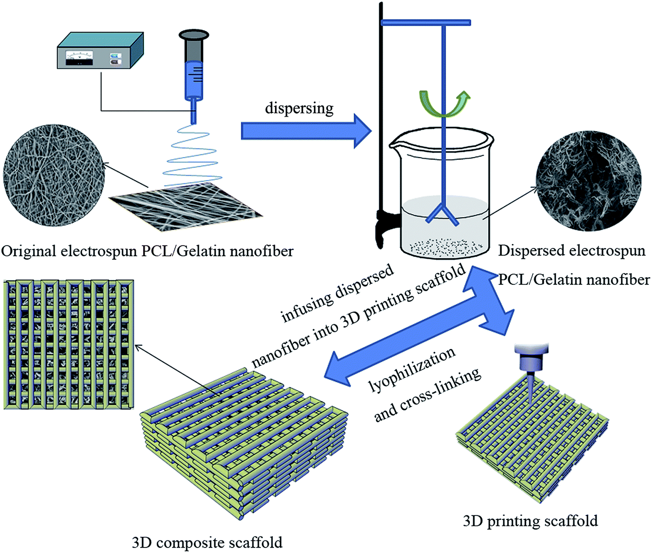 | ||
| Fig. 1 Schematic of the composite scaffold with electrospinning and 3D printing technology. (step (1) PCL/gelatin was fabricated with nanofibers, and then treated to disperse the nanofibers; step (2) PCL was printed to the 3D scaffold; step (3) the dispersed nanofibers were filled into the meshes of 3D printing scaffold to fabricate the 3D composite scaffold.) | ||
In addition, a pure 3D printing scaffold and a lyophilized electrospun scaffold were fabricated as control. The 3D printing PCL scaffold was prepared without infusing PCL/gelatin short nanofibers. The lyophilized electrospun scaffold was prepared by infusing PCL/gelatin short nanofibers in a 2 × 2 × 0.5 cm3 mold (the same size as with the printing PCL scaffold), and after freeze-drying, the lyophilized electrospun scaffold was also crosslinked with 2.5% glutaraldehyde solution.
2.4. Characterization of electrospun nanofibers and 3D composite scaffold
where mW is the wet weight of scaffold, mD is the dry weight of scaffold, and mS is the wet weight suspended in ethanol. The average porosity of each sample was tested five times.

where Δstress (MPa) is the stress value at the initial stage of compression, and Δstrain (%) is the corresponding strain value.

2.5. Cell culture and seeding
Mouse pre-osteoblastic cells (MC3T3-E1) were cultured in Alpha Minimum Essential Medium containing 10% fetal bovine serum (FBS) and 1% streptomycin/penicillin and maintained at 37 °C in a CO2 incubator. The media were changed with fresh medium every two days. The scaffolds were cut to a block of 1 cm length, 1 cm width and 0.3 cm height, placed into 48-well plates. Then, all the specimens were sterilized with 75% ethanol immersion and UV radiation for 12 h, then washed with PBS three times and soaked in cell culture medium for 2 h.When the cells had grown to the logarithmic phase, MC3T3-E1 cells were digested with 2.5% trypsin and seeded at a density of 1 × 10⁴ cells per well on different samples (the tissue culture plate (TCP) group was set as control). Cells were cultured for a period of 14 days.
2.6. Cell proliferation analysis and fluorescence staining
Cells viability on different scaffolds was measured by a Cell Counting Kit-8 (CCK-8) assay (n = 3 for each group).28 After culture for 1, 3, 5, 7 and 14 days, the samples were moved to a new well (the cell numbers that grow on the scaffolds should be measured on the plate), 5 mg mL−1 CCK-8 agent was added to each new well. 4 hours later, aliquots (100 μL) were pipetted into the wells of a 96-well plate and measured by an Enzyme-labeled Instrument (AMR-100, Hangzhou AoSheng Instrument Co., Ltd., China) at an UV absorbance of 450.Cell morphology was observed by inverted fluorescence microscope after 14 days of culture. All of the samples were rinsed twice with PBS and fixed in 4% paraformaldehyde for 2 h. Then each sample was treated with 1% TritonX-100 and bovine serum albumin (BSA) for 5 min and 20 min, respectively. 4′,6′-Diamidino-2-phenylindolehydrochloride (DAPI, Invitrogen, USA) and rhodamine-labeled phalloidin (Invitrogen, USA) were used to stain the nuclei and cytoskeletons of MC3T3-E1 cells. Before every step, the samples were washed with PBS three times, which is the same as the staining step. Eventually, the stained cells were observed and pictures taken with inverted fluorescence microscope (H600L, Nikon, Japan).
2.7. Cell infiltration and H&E staining
Cell infiltration studies on the scaffolds were performed using hematoxylin–eosin (H&E) stain. After 14 days culturing, the cell-scaffold constructs were removed from the media and rinsed three times with PBS solution and fixed with 4% paraformaldehyde solution for 2 h. Then the samples were embedded with paraffin and sliced for H&E staining. Finally, the cell infiltration results were observed with an inverted fluorescence microscope (H600L, Nikon, Japan).2.8. Statistical analysis
All the quantitative data were expressed as a mean ± standard deviation (SD). The statistical analysis was carried out using one-way ANOVA and a value of p < 0.05 was considered statistically significant.3. Results and discussion
3.1. Characterization of electrospun PCL/gelatin nanofibers before and after dispersing
In order to fill electrospun PCL/gelatin nanofibers into the meshes of a 3D printing scaffold, the original PCL/gelatin nanofibers were dispersed with a high speed dispersion homogenizer. The SEM morphology of electrospun PCL/gelatin nanofibers before and after dispersing is shown in Fig. 2A and B, respectively. These show that PCL/gelatin nanofiber is smooth and continuous before dispersing; however, after treatment, the nanofiber become dispersed and disconnected. A larger and greater porosity of the dispersed PCL/gelatin nanofiber compare to that of the original nanofiber was observed, and micron-sized pores were observed as well. Fig. 2C and D shows the nanofiber diameter distribution of PCL/gelatin nanofiber before and after dispersing, and indicate that both kinds of nanofiber were uniform. The diameters of the original nanofiber and the dispersed nanofiber were 751.22 ± 159.06 nm and 764.55 ± 283.29 nm, respectively, which has no significant difference. | ||
| Fig. 2 SEM images of electrospun PCL/gelatin nanofiber (A) before and (B) after dispersing, and the nanofiber diameter distribution of electrospun PCL/gelatin nanofiber (C) before and (D) after dispersing; (E) FTIR, (F) XRD, (G) TG and (H) DTG curves of two kinds of electrospun nanofiber ((a) is the original electrospun nanofiber, (b) is the dispersed electrospun nanofiber). | ||
Besides morphological characterization, FTIR, XRD and thermal analysis were evaluated to investigate the physical and chemical properties of the dispersed PCL/gelatin nanofiber. Fig. 2E shows the FTIR spectra (4000–500 cm−1) of the original PCL/gelatin nanofiber (a) and dispersed PCL/gelatin nanofiber (b). There are absorption peaks in both samples at 2939, 2868 and 1239 cm−1, which correspond to asymmetric CH2 stretching, symmetric CH2 stretching, and Asymmetric C–O–C stretching, respectively, on the PCL molecular chain. The absorption peaks at 1729, 1641, and 1548 cm−1 are attributed to C![[double bond, length as m-dash]](https://www.rsc.org/images/entities/char_e001.gif) O stretching, amide I and amide II on gelatin. There are no differences between the FTIR results of the two samples, and also observed for XRD (Fig. 2F), TG (Fig. 2G) and differential thermogravimetric (DTG, Fig. 2H) methods. XRD result showed that the specific diffraction peak located at 21.8° was attributed to the crystal of the PCL polymer. TG and DTG curves of the PCL/gelatin nanofiber indicated that the nanofiber is thermally stable before 200 °C, and the maximum weight loss occurred between 300 and 400 °C. Generally, it was documented that, except for morphology, the nanofiber diameter, physical and chemical properties of dispersed PCL/gelatin nanofiber had no significant changes during the dispersion process.
O stretching, amide I and amide II on gelatin. There are no differences between the FTIR results of the two samples, and also observed for XRD (Fig. 2F), TG (Fig. 2G) and differential thermogravimetric (DTG, Fig. 2H) methods. XRD result showed that the specific diffraction peak located at 21.8° was attributed to the crystal of the PCL polymer. TG and DTG curves of the PCL/gelatin nanofiber indicated that the nanofiber is thermally stable before 200 °C, and the maximum weight loss occurred between 300 and 400 °C. Generally, it was documented that, except for morphology, the nanofiber diameter, physical and chemical properties of dispersed PCL/gelatin nanofiber had no significant changes during the dispersion process.
3.2. Morphology of electrospinning/3D printing composite scaffold
The composite bone tissue engineering scaffold was fabricated by electrospinning and 3D printing; there are three steps of the procedure, which are shown in Fig. 1. In the first step, the electrospun PCL/gelatin nanofiber film was dispersed into discontinuous nanofibers (Fig. 1). Secondly, a pure 3D PCL scaffold was printed at 80 °C. Finally, PCL/gelatin short nanofibers were infused into the meshes of the printing PCL scaffold. Meanwhile, the PCL/gelatin dispersed nanofibers were used to fabricate a lyophilized electrospun scaffold as the control group, and a pure 3D printing scaffold was also set as control. Fig. 3 shows three kinds of sample digital photos and SEM images. It was observed that lyophilized electrospun scaffold consisted of discontinuous nanofibers with large porosity (Fig. 3A and B). The pore size is micro-scale (100–300 μm), which is large enough for cell migration and infiltration. Electrospinning is a common approach to fabricate a tissue engineering scaffold, because it can provide a nano-scale and extracellular matrix-mimicking structure with a high surface area and porosity.29 However, there is an important drawback of the electrospinning method, i.e. the pore size is nano-scale, which is shown in Fig. 2A, so it is difficult for the cells to migrate and infiltrate into the electrospun scaffold.15 In this study, the electrospun scaffold, casted with dispersed nanofibers, could offer a micro size pores. In addition, the dispersed nanofibers were easy to infuse and inject. The 3D printing PCL scaffold morphology is shown in Fig. 3C and D, which show that the 3D printing scaffold has a mesh structure, with PCL fiber diameter and mesh size of 0.39 ± 0.02 mm and 1 ± 0.05 mm, respectively, which can be controlled with a software program. However, 3D printing resolution limits the device. If the mesh size is small, it is very difficult to control; if the mesh size is big, cells are difficult to adhere and grow on the printing scaffold. Therefore, the electrospun PCL/gelatin dispersed nanofibers were infused into the mesh of a 3D printing PCL scaffold to fabricate a composite bone tissue engineering scaffold (Fig. 3E and F). It was found that dispersed PCL/gelatin nanofibers were obviously filling into the meshes of 3D printing PCL scaffold.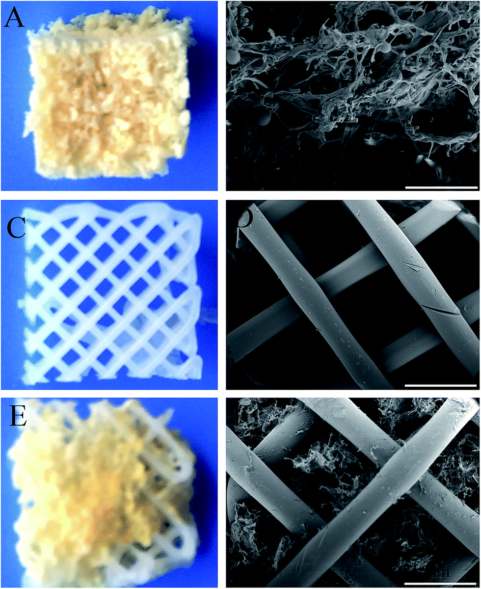 | ||
| Fig. 3 Digital photos of (A) lyophilized electrospun scaffold, (C) 3D printing scaffold and (E) 3D composite scaffold; SEM images of (B) lyophilized electrospun scaffold, (D) 3D printing scaffold and (F) 3D composite scaffold. | ||
The porosities of the lyophilized electrospun scaffold and composite scaffold were measured (Table 1). It shows that the lyophilized electrospun scaffold with dispersed nanofibers has a high porosity (95.34 ± 4.56%), and by filling it into a 3D printing scaffold, the porosity of the 3D printing scaffold increased to 79.32 ± 8.32%. The high porosity of the 3D scaffold must be better for cell migrating and infiltrating.
| Samples | Porosity (%) |
|---|---|
| Lyophilized electrospun scaffold | 95.34 ± 4.56 |
| 3D printing scaffold | — |
| 3D composite scaffold | 79.32 ± 8.32 |
3.3. Mechanical properties of 3D scaffolds
For bone tissue engineering applications, the mechanical properties of the scaffold are very important.30 PCL is a kind of thermoplastic material, which keeps a solid state below 60 °C and has good mechanical properties. Meanwhile, the polymer of PCL has good biocompatibility and is commonly used in the tissue engineering field. In this study, PCL was used to print the mesh scaffold to provide mechanical properties for a bone tissue engineering scaffold. The stress–strain curve is shown in Fig. 4. It significantly shows that the 3D printing scaffold has good mechanical properties, and the compressive modulus is 58.33 ± 1.85 MPa. On the other hand, PCL has a good elasticity because of the linear structure of the PCL molecule, and it has been determined that pure PCL electrospun nanofibers are difficult to break and cut.31 Gelatin has a good biocompatibility but the mechanical properties are not sufficient for bone tissue applications.32 Accordingly, the brittle and friable natural material gelatin was used to blend PCL with the electrospun nanofibers. In the end, the mechanical testing result showed that the compressive modulus of the composite scaffold is 30.50 ± 0.82 MPa, significantly higher than that of the electrospun scaffold (18.55 ± 0.56 MPa) (P < 0.05). This indicates that the 3D printing scaffold can significantly increase the mechanical properties of the 3D composite scaffold (P < 0.05). | ||
| Fig. 4 (A) Stress–strain curve and (B) compressive modules of three kinds of scaffold. | ||
3.4. Cell proliferation and morphology on the 3D scaffolds
MC3T3-E1 cells were cultured and seeded on the 3D composite scaffold, both the lyophilized electrospun scaffold and the 3D printing scaffold were set as the positive control group, whereas tissue culture plate (TCP) was set as a negative group. After culturing for 1, 3, 5, 7 and 14 days, the proliferation behaviors of the MC3TC-E1 cells on the scaffolds and TCP were evaluated via CCK-8 assay (Fig. 5). During the cultivation, cells show a lower proliferation on the 3D printing scaffold than on the TCP group (after culture for 7 days, these difference levels are more significant, P < 0.05), but it still remains a proliferation trend. It was documented that the PCL print scaffold is non-toxic and biocompatible, while cells are hard to adhere and grow on them with the mesh structure. For the group of the lyophilized electrospun scaffold, MC3T3-E1 cells showed the highest proliferation compared to the other groups, which might be contributed to the highest porosity structure of the micro-scale scaffold and the better biocompatibility of the gelatin material. In addition, cells also show a better proliferation behavior on the 3D composite scaffold than on the 3D printing scaffold and negative group (P < 0.05). It was concluded that the electrospinning/3D printing composite scaffold has a good biocompatibility of the materials and good structures for cell migration and proliferation. | ||
| Fig. 5 CCK-8 results of MC3T3-E1 cells cultured on the scaffolds. | ||
After 14 days of culture, MC3T3-E1 cells on the three kinds of scaffold were stained with fluorescence staining (DAPI for nuclei and rhodamine-labeled phalloidin for cytoskeletons). The results are exhibited in Fig. 6. MC3T3-E1 cells performed good migration and proliferation on the scaffolds, which showed good biocompatibility. The results corresponded to the CCK-8 assay results. There are a few cells that adhere to the surface of the 3D printing scaffold, but it is easier to migrate and grow on the lyophilized electrospun scaffold and 3D composite scaffold.
 | ||
| Fig. 6 Cytoskeletons fluorescence staining (red) images for MC3T3-E1 culture 14 days on (A) TCP, (C) lyophilized electrospun scaffold, (E) 3D printing scaffold and (G) 3D composite scaffold; nuclei fluorescence staining (blue) images of MC3T3-E1 after culture 14 days on (B) TCP, (D) lyophilized electrospun scaffold, (F) 3D printing scaffold and (H) 3D composite scaffold. Scale bar = 400 μm. | ||
3.5. Cell infiltrate characterization of H&E staining
In order to investigate whether the cell can infiltrate and grow into the scaffold, the cell-scaffold constructs were embedded with paraffin to slice, and then stained with H&E dye (Fig. 7). Lots of cells were observed on the lyophilized electrospun scaffold and 3D composite scaffold; by contrast, there are few cells on the 3D printing scaffold. Cell positive area values were calculated by Image J software, from which the lyophilized electrospun scaffold (35.25 ± 1.25%) and the 3D composite scaffold (29.55 ± 4.54%) were significantly higher than 3D printing scaffold (3.60 ± 2.58%) (P < 0.05). It was suggested that MC3T3-E1 cells could infiltrate into lyophilized electrospun scaffold and 3D composite scaffold; however, it was difficult to grow into the PCL printing scaffold. The research results of the cell culture indicated that the electrospinning/3D printing scaffold not only has a good biocompatibility, but also provides a porosity structure for cell infiltration and migration, which suggests the potential use of these scaffolds for bone tissue engineering. | ||
| Fig. 7 H&E staining results of MC3T3-E1 culture 14 days on (A) lyophilized electrospun scaffold, (B) 3D printing scaffold and (C) composite scaffold; (D) the proportion of cell positive area of three kinds of scaffold. Scale bar = 200 μm. | ||
In bone tissue engineering, the natural ECM of bone tissue is composite with a 3D porous network composed of collagen fibers that form hierarchical structures from nanometer length multi-fibrils to macroscopic tissue architecture. The structures generated by electrospinning and 3D printing contain nanofibers with micro-interconnected pores, resembling the topographic features of the bone ECM. Therefore, on the one hand, the 3D composite scaffold could be a great biomimetic bone tissue in the microscopic structure, and on the macroscopic structure, 3D printing technology provides the customization for bone defect models. On the other hand, the 3D composite scaffold has a sufficient mechanical property for bone regeneration. Generally, the 3D composite scaffold shows a good potential in bone tissue engineering applications. In addition, further study will focus on applying additional growth factors, such as BMP-2 and TGF (because gelatin has lots of functional groups, which is easy to graft growth factors), monitoring gene expression and performing animal trials to determine the function of the composite scaffold.
4. Conclusion
In this study, we fabricated a 3D composite scaffold using the approach of electrospinning and 3D printing technology. The original nanofibers of electrospun PCL/gelatin were cut to discontinuous nanofibers. Then the dispersed nanofibers were filled into the mesh of a PCL printing scaffold to fabricate a 3D composite scaffold. With the support of the 3D printing scaffold, the 3D composite scaffold shows a good mechanical stress, the compressive modulus is 30.50 ± 0.82 MPa, which is significantly higher than that of the lyophilized electrospun scaffold. CCK-8 experiments and fluorescence staining indicated that the composite scaffold not only has a good biocompatibility, but was also good for cell migration and proliferation compared to the 3D printing scaffold. In addition, according to H&E staining, MC3T3-E1 cells can be infiltrated into the micro pores of a lyophilized electrospun scaffold and 3D composite scaffold. Therefore, the electrospinning/3D printing composite scaffold has a potential to repair and regenerate bone tissue.Acknowledgements
This research was supported by National Nature Science Foundation of China (81371979).References
- C. Xu, P. Su, X. Chen, Y. Meng, W. Yu, A. P. Xiang and Y. Wang, Biomaterials, 2011, 32, 1051–1058 CrossRef CAS PubMed
.
- B. Sun, J. Li, W. Liu, B. M. Aqeel, H. El-Hamshary, S. S. Al-Deyab and X. Mo, Iran. Polym. J., 2014, 24, 29–40 CrossRef
- J. Venkatesan and S. K. Kim, J. Biomed. Nanotechnol., 2014, 10, 3124–3140 CrossRef CAS PubMed
- K. Rezwan, Q. Z. Chen, J. J. Blaker and A. R. Boccaccini, Biomaterials, 2006, 27, 3413–3431 CrossRef CAS PubMed
- S. S. Liao, F. Z. Cui, W. Zhang and Q. L. Feng, J. Biomed. Mater. Res., Part B, 2004, 69, 158–165 CrossRef CAS PubMed
- J. R. Porter, T. T. Ruckh and K. C. Popat, Biotechnol. Prog., 2009, 25, 1539–1560 CAS
- H. Seitz, W. Rieder, S. Irsen, B. Leukers and C. Tille, J. Biomed. Mater. Res., Part B, 2005, 74, 782–788 CrossRef PubMed
- Q. Yao, B. Wei, Y. Guo, C. Jin, X. Du, C. Yan, J. Yan, W. Hu, Y. Xu, Z. Zhou, Y. Wang and L. Wang, J. Mater. Sci.: Mater. Med., 2015, 26, 1–9 CAS
- M. Castilho, C. Moseke, A. Ewald, U. Gbureck, J. Groll, I. Pires, J. Teßmar and E. Vorndran, Biofabrication, 2014, 6, 015006 CrossRef PubMed
- E. Dalimier and D. Salomon, Dermatology, 2012, 224, 84–92 CrossRef PubMed
- J. G. Kwan, Design of electronics for a high-resolution, multi-material, and modular 3D printer, Massachusetts Institute of Technology, 2013 Search PubMed
- H. Yoshimoto, Y. M. Shin, H. Terai and J. P. Vacanti, Biomaterials, 2003, 24, 2077–2082 CrossRef CAS PubMed
- N. Bhardwaj and S. C. Kundu, Biotechnol. Adv., 2010, 28, 325–347 CrossRef CAS PubMed
- J. Rnjak-Kovacina, S. G. Wise, Z. Li, P. K. M. Maitz, C. J. Young, Y. Wang and A. S. Weiss, Biomaterials, 2011, 32, 6729–6736 CrossRef CAS PubMed
- C. Vaquette and J. J. Cooper-White, Acta Biomater., 2011, 7, 2544–2557 CrossRef CAS PubMed
- B. Lee, M. Shafiq, Y. Jung, J. C. Park and S. H. Kim, Macromol. Res., 2015, 1–12 Search PubMed
- K. Wang, M. Zhu, T. Li, W. Zheng, L. Li, M. Xu, Q. Zhao, D. Kong and L. Wang, J. Biomed. Nanotechnol., 2014, 10, 1588–1598 CrossRef CAS PubMed
- Y. Si, J. Yu, X. Tang, J. Ge and B. Ding, Nat. Commun., 2014, 5, 5802 CrossRef PubMed
- X. He, F. Bei, C. Huang, W. Hao, G. Yang, R. Hu, Y. Meng, Z. Xu, W. Wei and F. Wei, Int. J. Nanomed., 2015, 10, 2089–2099 CAS
- L. D. Wright, R. T. Young, T. Andric and J. W. Freeman, Biomed. Mater., 2010, 5, 7836–7845 Search PubMed
- K. Tuzlakoglu, M. I. Santos, N. Neves and R. L. Reis, Tissue Eng., Part A, 2011, 17, 463–473 CrossRef CAS PubMed
- S. Radin, J. T. Campbell, P. Ducheyne and J. M. Cuckler, Biomaterials, 1997, 18, 777–782 CrossRef CAS PubMed
- D. W. Hutmacher, Biomaterials, 2000, 21, 2529–2543 CrossRef CAS PubMed
- L. M. Ott, T. A. Zabel, N. K. Walker, A. L. Farris, J. T. Chakroff, D. G. Ohst, J. K. Johnson, S. H. Gehrke, R. A. Weatherly and M. S. Detamore, Biomed. Mater., 2016, 11, 025020 CrossRef PubMed
- J. L. Sang, N. H. Dong, S. P. Ji, S. K. Kwon, H. L. Jin, J. H. Lee, D. K. Wan, K. I. Keun, A. P. Su and S. P. Ji, Phys. Chem. Chem. Phys., 2014, 17, 2996–2999 Search PubMed
- J. H. Ko, H. Y. Yin, J. An, J. C. Dong, J. H. Kim, S. B. Lee and D. G. Pyun, Macromol. Res., 2010, 18, 137–143 CrossRef CAS
- N. O. Engin and A. C. Tas, J. Eur. Ceram. Soc., 1999, 19, 2569–2572 CrossRef CAS
- H. Fan, J. Hui, Z. Duan, D. Fan, Y. Mi, J. Deng and H. Li, BioMed Res. Int., 2014, 2014, 652432 Search PubMed
- T. J. Sill and H. A. V. Recum, Biomaterials, 2008, 29, 1989–2006 CrossRef CAS PubMed
- D. Howk and T. M. Chu, Biomed. Sci. Instrum., 2006, 42, 278–283 Search PubMed
- G. H. Kim, Biomed. Mater., 2008, 3, 025010 CrossRef PubMed
- T. J. Ambrosio, Drug Dev. Ind. Pharm., 2008, 16, 995–1010 Search PubMed
| This journal is © The Royal Society of Chemistry 2016 |