Controllable synthesis of biosourced blue-green fluorescent carbon dots from camphor for the detection of heavy metal ions in water

Rohit Ranganathan Gaddamab, D. Vasudevanc, Ramanuj Narayana and K. V. S. N. Raju*a
aPolymers and Functional Materials Division, Indian Institute of Chemical Technology, Tarnaka 500007, Andhra Pradesh, India. E-mail: kvsnraju@iict.res.in; drkvsnraju@gmail.com; Fax: +91 40 27193991; Tel: +91 40 27193991
bAmity Institute of Nanotechnology, Amity University, Noida 201301, Uttar Pradesh, India
cElectrodics and Electrocatalysis Division, Central Electrochemical Research Institute, Karaikudi-630006, Tamil Nadu, India

Received 15th September 2014 , Accepted 20th October 2014

First published on 20th October 2014


Abstract

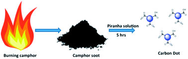
A robust method for the synthesis of fluorescent carbon dots (C dots) from camphor, which provides an insight into the mechanism of C dot formation, is reported. Camphor is a biosourced hydrocarbon, which contains an hexagonal ring arranged like an open book. Burning of camphor leads to the formation of soot, which comprises graphitic domains. The soot when treated with piranha solution disintegrates into smaller domains leading to the formation of C dots with a size distribution of ∼1–4 nm. The C dots obtained were carboxyl terminated which was confirmed from the infrared spectroscopic measurements. The D and G bands at ∼1314 cm−1 and ∼1586 cm−1, respectively, found using Raman spectroscopy and the peaks at 25.01° found using X-ray diffraction of C dots confirm the presence of graphitic domains. Photoluminescence studies were carried out which reveal exceptional fluorescence in the as prepared C dots. Interestingly the quantum yield is found to be around 21.16%, which is significantly higher than the values reported in previous papers. The current study deals with the sensing of metal ions. Heavy metal cations such as Cd2+ and Hg2+ were used to check whether they affect the fluorescence properties of C dots. It was found that other metal ions like Cu2+, Fe2+ and Zn2+ also quenched the fluorescence of C dot with a different quenching profile.


1. Introduction

Carbon is one of the most interesting materials because of its diverse chemical nature which makes it the most targeted material for industrial applications.1 Many of the carbon nanomaterials such as nanotubes, nanofibers, nanorods, graphene and so on, are widely researched and already well established.2 Recently, carbon dots (C dots) have attracted a lot of attention because of their unique physico-chemical properties. Until recently, carbon-based materials were expected to be black in colour, with a low solubility in water and weak or no fluorescence. However, C dots are highly fluorescent, water soluble and less than 10 nm in size.3 They also possess exceptional properties such as high optical absorptivity, chemical stability, low toxicity and biocompatibility.4 As a result they find potential applications in multiple fields such as medical diagnosis,4 bio-imaging,5 sensing6 and photovoltaics.7,8 Several top-down approaches such as laser ablation,9 arc discharge2 and plasma treatment10 have been employed for the synthesis of C dots. Most of these methods involve the use of toxic precursors and high-end equipments, which are not cost-effective. In order to overcome these drawbacks, certain bottom-up approaches have been employed for the synthesis of C dots. These involve carbonization of sugars, glycerol and so on. Even in these cases, the method needs to employ several reaction stages, and uses strong acids and other agents to improve the solubility and fluorescence of the C dots thus obtained. These methods are also costly and time consuming.11 As an advancement in the C dot synthesis, single step preparation methods for C dots were established that involve hydrothermal carbonization of chitosan, microwave synthesis and solution chemistry. However, even these methods suffer from drawbacks pertaining to time, stringent synthetic conditions and high cost. Considering the previously mentioned drawbacks, C dots have recently been synthesized by using eco-friendly, bio-precursors such as soy milk,12 orange juice,13 banana juice14 and so on. Even using these, the size of the C dots obtained was not as uniform as expected.

In the present work, the synthesis of water-soluble fluorescent C dots from biological sourced hydrocarbon is reported. In this research, camphor (C10H16O) is used as a precursor material for the synthesis of C dots. Camphor is a natural hydrocarbon obtained from the tree Cinnamomum camphora. It is a waxy, flammable, crystalline substance, which is white in colour, and volatile in nature.15 It is a bicyclic saturated terpene, which exists in the optically active dextro and levo forms and also as a racemic mixture of the two forms. The dextro form is the most naturally occurring form that occurs in the wood and leaves of the camphor tree. The soot obtained from the incineration of camphor is non-toxic and has also been used in India for centuries for facial decoration. Camphor has been used in the preparation of carbon nanotubes, graphene, carbon nano-onions, carbon nanoparticles and so on, using chemical vapour deposition laser ablation and other methods.16–22 To the best of our knowledge there is no report on the synthesis of C dots from camphor soot. The main reason to use camphor as a starting material is because of its renewable biological origin. Also camphor is comparatively cheaper and is an easily available source for the synthesis of C dots. Therefore, it is possible to synthesize C dots in bulk quantities.

For the synthesis of C dots (Fig. 1), camphor was initially subjected to incineration followed by collection of the soot on a polished copper surface. The camphor soot was subjected to treatment with piranha solution [a mixture of sulfuric acid (H2SO4) and hydrogen peroxide (H2O2)], and the resulting mixture was then filtered. The filtrate obtained was bright yellow in colour under normal light and a bluish-green in colour when placed under ultraviolet (UV) light. The C dots obtained were then neutralized with sodium hydroxide and then subjected to dialysis. The C dots were in the size range of 1–4 nm and also stable in water. The C dot solution was then used for the detection of heavy metal cations such as mercury and cadmium together with other cations such as iron(II), zinc and copper(II) in water by measuring the change in their fluorescence.


image file: c4ra10471d-f1.tif
Fig. 1 Illustration of the formation of C dots from the thermal dissociation of camphor.

2. Experimental

2.1. Materials

Camphor was obtained from the local market. Concentrated sulfuric acid, 30% hydrogen peroxide solution, mercuric chloride and cadmium chloride, ferrous sulfate, zinc sulfate and cupric chloride were all purchased from SD Fine-Chem, Mumbai. All the chemicals were used as received without any further purification.

2.2. Synthesis of C dots

Camphor (5 g) was placed in a copper crucible and subjected to combustion. The 300 mg of soot obtained was collected on a polished copper plate. The soot was then treated with piranha solution [H2SO4[thin space (1/6-em)]:[thin space (1/6-em)]H2O2 (7[thin space (1/6-em)]:[thin space (1/6-em)]3)] for 15 hours. Following this, the piranha solution was diluted with water and the mixture was filtered. The 200 mg of black soot remained in the filter paper and the C dots obtained were left behind in the piranha solution. The piranha solution was then neutralized with sodium hydroxide, which lead to salt formation. Dialysis was then performed to obtain the pure C dots in water. The dialysis tubing used in this dialysis process was a cellulose membrane. The outside and inside of the dialysis tubing was rinsed with 20 ml of deionized water for 15 to 30 minutes to remove the sodium azide preservative. The water was poured out and the step repeated with another 20 ml of deionized water. The dialysis was done over three days by immersing the dialysis tube containing the sample in deionized water. The deionised water was changed in every two hours. The sample solution inside the tubing contained the pure C dots that were used for further characterization.

2.3. Preparation of salt solutions

Samples of mercuric chloride, cupric chloride, ferric sulphate, zinc sulfate and cadmium chloride (all AR grade) were used for studies on the fluorescence quenching of C dots upon addition of these metal ions. A 0.1 M stock solution of each of these compounds was prepared. A 2 ml solution of C dots was placed in the cuvette for fluorescence measurement. To this, increasing amounts of ions (0.5, 1, 1.5 μM and so on) were added. With each addition, the solution was stirred and the fluorescence measured.

2.4. Instruments

Fourier transform infrared (FTIR) spectrographs of the synthesized samples were recorded using a Thermo Nicolet Nexus 670 spectrometer. Raman spectra were recorded using Horiba Jobin Yvon Raman spectrometer with a laser excitation wavelength of 632.81 nm. Transmission electron micrographs (TEM) of the carbon nanoparticles were recorded using a Jeol JEM-100CX electron microscope. X-ray diffraction (XRD) patterns of camphor soot were obtained using a Siemens D5000 X-ray diffractometer with Cu Kα radiation of wavelength 1.54 nm. The crystalline phase of C dot was investigated using a Philips X'Pert PRO X-ray diffractometer. Fluorescence spectroscopy was performed using a Horiba FluoroMax 4 spectrophotometer at different excitation wavelengths. UV-vis absorption spectra were obtained using a Shimadzu 220 V (E) UV-vis spectrophotometer.

3. Results and discussion

It is well known that camphor is a naturally occurring hydrocarbon that posses 10 atoms out of which seven are associated with the ring system and the rest are methyl carbons. Camphor has a hexagonal ring arranged like an open book as opposed to that of graphite which has a planar arrangement. The burning of camphor could lead to the formation of hexagonal and pentagonal radicals (Fig. 2). They combine together to form a channel type of structure possessing graphitic domains which lead to the formation of camphoric carbon soot.1,23 The XRD profile of camphor soot reveals the presence of graphitic domains. The XRD peaks of the camphor soot possess two prominent peaks at 25.6° and 43.6° which can be attributed to the (002) and (100) planes of hexagonal graphite (Fig. S1). The Raman profile of camphor soot (Fig. S2) reveals the presence of a D band and a G band around 1330 cm−1 and 1586 cm−1, which also confirms the presence of graphitic domains. This soot when treated with piranha solution followed by filtration not only terminates the soot with a carboxyl group but also leaves behind C dots in the filtrate. The piranha solution contains a mixture of H2SO4 and H2O2, which react together to produce hydronium ions, bisulfate ions and atomic oxygen. The atomic oxygen allows the piranha solution to dissolve the elemental carbons. Generally camphor soot is difficult to attack chemically, because of its potential stability and the sp2 hybridized surface carbon atoms (Fig. S3). However, the nascent oxygen directly attaches on to the surface of camphor soot, forming a carbonyl group. The oxygen atom deceptively takes an electron bonding pair from the central carbon and forms a carbonyl group, while simultaneously disrupting the bonds of the target carbon atom with one or more of its neighbours, therefore, facilitating the breakdown of soot into smaller carbon materials. This is a cascading effect where the single atomic oxygen initiates disentanglement of the local bonding structure, which in turn allows the whole range of the reaction to affect the carbon atoms, finally leading to the formation of C dots.24,25 The XRD profile (Fig. S4) of the C dot also reveals the pattern of disordered carbon at 25.01°, which is very close to the graphitic (002) plane of hexagonal graphite.
image file: c4ra10471d-f2.tif
Fig. 2 Possible mechanism for the formation of C dots from the thermal dissociation of camphor.

The C dots treated with piranha solution are acidic in nature, thus, it is necessary to neutralize the solution up to pH 7. For this reason sodium hydroxide was used which eventually led to the formation of salt. Therefore, it was important to perform dialysis to ensure the purity of C dots. The initial C dots (before dialysis) were observed under TEM (Fig. 3a) which revealed that the majority of the C dots have a size of ∼1–4 nm (Fig. S5). Following the dialysis, the salt was removed and pure C dots of size ∼4–8 nm (Fig. 3b) were obtained in water. The TEM images reveal that the C dots are finely dispersed and mostly spherical in nature with little or no agglomeration. However, the increase in size of pure C dots is most likely to be because of the formation of hydrogen bonds between the carboxyl groups present on the surface of the C dot as revealed by the FTIR analysis. The FTIR spectra (Fig. 4a) also exhibit C–O stretching frequency at around 1124 cm−1. The peak at 1630 cm−1 could be attributed to the stretching frequency C[double bond, length as m-dash]O of aromatic carbonyl; the two peaks around 1440 and 1560 cm−1 originate from the presence of aromatic C[double bond, length as m-dash]C; and the band at 3000–3400 cm−1 is indicative of O–H and N–H stretching frequencies, respectively. Prior to dialysis the C dots show similar peaks in the FTIR spectra (Fig. S6). However, there are certain differences in the spectra of C dots before and after dialysis. It can be seen that the absorption spectrum of C[double bond, length as m-dash]O of pure C dot appears at a relatively low frequency of 1630 cm−1 compared to that of its non-dialysed counterpart (1635 cm−1). This indicates that there is a ‘red shift’ of the carboxyl group from 1635 to 1630 cm−1 that may result from intermolecular hydrogen bonding between the C dots. The formation of hydrogen bonding will strengthen the interaction between the C dots and therefore, facilitates the increase in size of the C dots.26 Also, it is noticed that the peak (1630 cm−1) of pure C dot is widened and its intensity is increased in comparison with its counterpart. The C dots before dialysis (Fig. S6) show a broad stretching band at 3445 cm−1 and the absorption band, which peaks at 1635 cm−1, corresponds to the –OH stretching frequency. The absorption band of –OH moves from 3445 to 3400 cm−1 for the pure C dots. Also in Fig. S6 the strong and broad peak centred at 1124 cm−1 and the small shoulder at 994 cm−1 could be assigned to vibrational stretching frequencies of sulfate. The strong and broad absorption band centred at 618 cm−1 probably resulted from the combined absorptions of sulfate, the Na–O stretching vibrations and the Na–OH wagging vibrational mode of molecular water. Therefore, this reveals that sodium sulfate is present in the carbon dots before dialysis. Pure carbon dots and also the camphor soot cease to have such sulfate absorption peaks in their FTIR spectra.


image file: c4ra10471d-f3.tif
Fig. 3 TEM images of (a) as prepared C dots with salt impurities, (b) C dots post-dialysis.

image file: c4ra10471d-f4.tif
Fig. 4 (a) FTIR spectra of a C dot and (b) Raman spectra (λex = 633 nm) of a C dot.

Raman spectra of graphitic carbon generally consist of two prominent bands, the G-band (G for graphite) and the D-band (D for defect). The D band arises at around 1350 cm−1, which corresponds to the A1g symmetry of the disordered graphite that also reveals the presence of graphitic domains in the carbon nanomaterial. The G-band is established at around 1580 cm−1. This band is accredited to a zone center mode of the E2g symmetry of a single crystal graphite. The Raman spectra of C dots clearly show the D-band near 1314.63 cm−1 and G-band at 1586.27 cm−1, which reveals similarities with that of graphitic carbon. Also a downward shift in the D- and G-bands of C dot as compared to camphor soot is observed. The intensity ratio of D- and G-bands (ID/IG) provides an insight into the extent of the disorder and the ratio of sp3/sp2 carbon atoms. The ID/IG ratio of the as prepared C dot is 1.284 whereas the ID/IG ratio of pristine camphor soot is 0.95. Fig. 4b shows a broad D-band, which implies the presence of increased disorder and decreased domain size.27 The recombination of the bonds of camphor soot during C dot formation introduces smaller graphitic domain sizes, leading to size distributions with a variety of bonding structures. These distributions cluster with different sizes and introduce a superposition of different Raman modes, which results in a broader linewidth for the C dots (Fig. 4b). The integrated intensity ratio between the G-band and the D-band is inversely proportional to the grain size of graphite. The average graphitic domain size calculated from the Raman spectra is 45.4 Å for camphor soot and 30.9 Å for pure C dots. These results support the broadening of the D-band and the shrinking of the domain size when compared to camphor soot.27,28

The absorption spectrum of C dot (Fig. 5a) shows an edge at around 325 nm and a narrow peak around 250 nm which could be associated with the π–π* transition of the nanocarbon.29 The C dots were also subjected to different excitation wavelengths from 320–600 nm (Fig. 5b). It is seen that with an increase in excitation wavelength the fluorescence peak shifted to higher wavelengths. The C dot also shows a blue fluorescence when exposed to UV light. Interestingly the quantum yield is found to be around 21.16%, which is significantly higher than the values reported previously.12–14 Therefore, there are potential applications for C dots in bio-labeling, sensing and opto-electronic devices. From the FTIR analysis it is clear that the C dots are terminated with a carboxyl group on the surface. Therefore, it is expected that the fluorescence properties change when they react with metal ions. Quenching of fluorescence may occur because of energy transfer, charge diversion or surface absorption. The quenching mechanisms could be either static or dynamic quenching. The heavy metal salts could be detected by using atomic absorption or emission spectroscopy, inductively coupled plasma mass spectroscopy or spectrophotometric detection using organic dyes. Although these methods are highly precise, the cost-effectiveness and ease of handling is the major concern.


image file: c4ra10471d-f5.tif
Fig. 5 (a) Absorption spectra of a C dot, inset: C dot showing a blue fluorescence when illuminated under a UV lamp. (b) Photoluminescence spectra of a C dot from 300 nm to 600 nm excitation with a 20 nm increase in each step. (c) Fluorescence quenching by the addition of (0.5 μl to 6 μl) of mercury salt in an increasing order into 2 ml of stock C dot solution (λex = 320 nm). (d) Stern–Volmer plot showing the dependency of fluorescence intensity on the concentration of Hg2+.

Therefore, easy and cost-effective approaches are required. Thus, C dots were used here for the detection of heavy metal ions in aqueous media. Heavy metal cations such as Cd2+ and Hg2+ were used to check if they affect the fluorescence properties of C dots. As shown in Fig. 3c, the fluorescence of C dots is affected by the addition of the mercury salt, where it is possible to observe a substantial quenching effect. The mercury(II) ion is among the most dangerous and ubiquitous pollutants, which is a potential threat to the environment and also to human health. It is well established that Hg2+ could easily penetrate the skin, gastrointestinal tissues and respiratory organs, finally leading to a fatal damage of the central nervous system followed by mitosis impairment and DNA damage.30 The fluorescence signal decreases upon addition of micromolar concentrations of Hg2+ (Fig. 6a). For semiconducting quantum dots the quenching of fluorescence is attributed to the effective electron transfer process via non-radiative electron–hole recombination annihilation.31 For C dots further research is required to establish a firm theory of fluorescence quenching with heavy metal ion addition. The Stern–Volmer plot of Hg2+ sensing is shown in Fig. 5d. It is interesting to note the non-linear nature of the Stern–Volmer plot over the concentration of Hg2+. This phenomenon means that the charge transfer mechanism between Hg2+ and C dots may be because of a non-dynamic (static) mechanism. In a static quenching mechanism the quenching occurs as a result of a non-fluorescent complex formation between the fluorophore and the quencher. However, this is just preliminary information; further investigation might be required to confirm the mechanism of the quenching.


image file: c4ra10471d-f6.tif
Fig. 6 Fluorescence quenching by the addition of metal ions (0.5 μl to 6 μl of salt in an increasing order into 2 ml of stock C dot solution) (a) Zn2+, (b) Cu2+, (c) Cd2+ and (d) Fe2+ (The excitation wavelength of λex = 320 nm was maintained).

The addition of Cd2+ also shows a substantial quenching effect but is comparatively less than that of mercury (Fig. 6). Because these C dots are non-toxic and biologically inert they are a potential solution for in vitro measurements of the mercury uptake dynamics. However, for the in vivo analysis of metal ions further research is needed to establish the effect of biological molecules on the speciation of the metal ions (cysteine residuals, proteins that are water soluble, other anionic cellular components, and so on) and their interaction with C dots. Apart from heavy metal ions such as Cd2+, other ions such as Cu2+, Fe2+ and Zn2+ were also used to quench the fluorescence of C dots (Fig. 6). It is easily observed from the graph that each ion shows a different profile of sensing. Fig. 7 shows the difference of the fluorescence intensity ratio (Fo/F) of the C dot solution in the absence and presence of various metal ions. Each ion is found to have a different Fo/F ratio compared to the other.32 It is seen that the sensing of a heavy metal cation in the presence of other metal ions might not be very favorable because of the sensing behavior of the C dot with other metal ions. This limitation could be overcome if it was possible to conjugate the C dot with other functional groups that are specific to the target material of interest. It is hoped that such investigation of sensing specific heavy metal ions will be carried out in the near future.


image file: c4ra10471d-f7.tif
Fig. 7 The various fluorescence intensity ratios (Fo/F) of the C dot solution in the absence and presence of various individual metal ions. Fo and F are the fluorescence intensity at 320 nm in the absence and presence of ions, respectively.

4. Conclusions

The present report focuses on the synthesis of C dots from camphor. Camphor being a green hydrocarbon and non-toxic means that the C dots are eco-friendly. Apart from this, the camphor soot and the C dots possess graphitic carbon domains, which were very evident from XRD and Raman analysis. C dots also have exceptional photoluminescence properties in the UV region and it is also evident from FTIR spectra that the C dots were carboxyl terminated. The quantum yield of C dots was found to be around 21.16%. Therefore, C dots were used as a simple but effective sensor. Heavy metal cations such as Cd2+ and Hg2+ were introduced and their complex interaction with the carboxyl group facilitated fluorescence quenching, which could be used to test the ion concentration in various water bodies. Also other cations such as Cu2+, Fe2+ and Zn2+ were used for probing. Each cation showed a different sensing profile in their fluorescence spectra. Although this can be correlated with specificity, this study is just a preliminary one. Further investigation into the method of fluorescence quenching, specificity in sensing by anchoring moieties onto the C dots and so on, needs to be carried out in future. C dots could open up potential research avenues for their use as an effective nanoprobe.

Acknowledgements

The present research work was supported by CSIR, India under the Intel-Coat Project (CSC-0114).

Notes and references

  1. R. R. Gaddam, S. Kantheti, N. R. Narayan and K. V. S. N. Raju, RSC Adv., 2014, 4, 23043–23049 RSC.
  2. S. Zhu, Q. Meng, L. Wang, J. Zhang, Y. Song, H. Jin and B. Yang, Angew. Chem., 2013, 125, 4045 CrossRef.
  3. L. Cao, M. J. Meziani, S. Sahu and Y. P. Sun, Acc. Chem. Res., 2013, 46, 171 CrossRef CAS PubMed.
  4. (a) L. Zhou, J. Liu, X. Zhang, R. Liu, H. Huang, Y. Liu and Z. Kang, Nanoscale, 2014, 6, 5831–5837 RSC; (b) W. Shang, X. Zhang, M. Zhang, Z. Fan, Y. Sun, M. Han and L. Fan, Nanoscale, 2014, 6, 5799–5806 RSC.
  5. B. Kong, A. Zhu, C. Ding, X. Zhao, B. Li and Y. Tian, Adv. Mater., 2012, 24, 5844 CrossRef CAS PubMed.
  6. Y. Fang, S. Guo, D. Li, C. Zhu, W. Ren, S. Dong and E. Wang, ACS Nano, 2012, 6, 400 CrossRef CAS PubMed.
  7. S. N. Baker and G. A. Baker, Angew. Chem., 2010, 122, 6876 CrossRef.
  8. V. Gupta, N. Chaudhary, R. Srivastava, G. D. Sharma, R. Bhardwaj and S. Chand, J. Am. Chem. Soc., 2011, 133, 9960 CrossRef CAS PubMed.
  9. X. Yan, X. Cui, B. Li and L.-S. Li, Nano Lett., 2010, 10, 1869 CrossRef CAS PubMed.
  10. Y. P. Sun, B. Zhou, Y. Lin, W. Wang, K. A. S. Fernando, P. Pathak, M. J. Meziani, B. A. Harruff, X. Wang, H. F. Wang, P. J. G. Luo, H. Yang, M. E. Kose, B. L. Chen, L. M. Veca and S. Y. Xie, J. Am. Chem. Soc., 2006, 128, 7756 CrossRef CAS PubMed.
  11. J. Wang, C. F. Wang and S. Chen, Angew. Chem., 2012, 124, 9431 CrossRef.
  12. H. Li, Z. Kang, Y. Liu and S. T. Lee, J. Mater. Chem., 2012, 22, 24230 RSC.
  13. C. Zhu, J. Zhai and S. Dong, Chem. Commun., 2012, 48, 9367 RSC.
  14. S. Swagatika, B. Birendra, K. M. Tapas and M. Sasmita, Chem. Commun., 2012, 48, 8835 RSC.
  15. B. De and N. Karak, RSC Adv., 2013, 3, 8286 RSC.
  16. P. Dubey, K. M. Tripathi and S. K. Sonkar, RSC Adv., 2014, 4, 5838–5844 RSC.
  17. J. Travas-Sejdic, N. Aydemir, B. Kannan, D. E. Williams and J. Malmström, J. Mater. Chem. B, 2014, 2, 4593–4609 RSC.
  18. M. Kumar and Y. Ando, Carbon, 2005, 43, 533–540 CrossRef CAS PubMed.
  19. M. Kumar and Y. Ando, J. Phys.: Conf. Ser., 2007, 61, 643 CrossRef CAS.
  20. P. R. Somani, S. P. Somani and M. Umeno, Chem. Phys. Lett., 2006, 430, 56–59 CrossRef CAS PubMed.
  21. L. F. Cui, L. Hu, J. W. Choi and Y. Cui, ACS Nano, 2010, 4, 3671–3678 CrossRef CAS PubMed.
  22. R. J. Andrews, C. F. Smith and A. J. Alexander, Carbon, 2006, 44, 341–347 CrossRef CAS PubMed.
  23. M. Kumar and Y. Ando, Diamond Relat. Mater., 2003, 12, 998–1002 CrossRef CAS.
  24. K. Mukhopadhyaya, K. M. Krishna and M. Sharon, Carbon, 1996, 34, 251–264 CrossRef CAS; D. Diemente, J. Chem. Educ., 1991, 68, 568 CrossRef.
  25. K. S. Koh, J. Chin, J. Chia and C. L. Chiang, Micromachines, 2012, 3, 427 CrossRef PubMed.
  26. W. Zhang, A. A. Dehghani-Sanij and R. S. Blackburn, Prog. Nat. Sci., 2008, 18, 801–805 CrossRef CAS PubMed.
  27. G. X. Chen, M. H. Hong, T. C. Chong, H. I. Elim, G. H. Ma and W. Ji, J. Appl. Phys., 2004, 95, 1455 CrossRef CAS PubMed.
  28. D. S. Knight and W. B. White, J. Mater. Res., 1989, 4, 385–393 CrossRef CAS.
  29. D. Pan, J. Zhang, Z. Li, C. Wu, X. Yana and M. Wu, Chem. Commun., 2010, 46, 3681 RSC.
  30. L. Zhou, Y. H. Lin, Z. Z. Huang, J. S. Ren and X. G. Qu, Chem. Commun., 2012, 48, 1147 RSC.
  31. Y. S. Xia and C. Q. Zhu, Talanta, 2008, 75, 215 CAS.
  32. F. Wang, Z. Gu, W. Lei, W. Wang, X. Xia and Q. Hao, Sens. Actuators, B, 2014, 190, 516–522 CrossRef CAS PubMed.

Footnote

Electronic supplementary information (ESI) available. See DOI: 10.1039/c4ra10471d

This journal is © The Royal Society of Chemistry 2014
Click here to see how this site uses Cookies. View our privacy policy here.