Capture and culturing of single microalgae cells, and retrieval of colonies using a perforated hemispherical microwell structure

Jong Seob Choia, Sunwoong Baea, Kyung Hoon Kima, Jaoon Y. H. Kimb, Sang Jun Simb and Tae Seok Seo*a
aDepartment of Chemical and Biomolecular Engineering (BK21 Program) and Institute for The BioCentury, Korea Advanced Institute of Science and Technology (KAIST), 291 Daehak-ro, Yuseong-gu, Daejeon, 305-701, South Korea. E-mail: seots@kasit.ac.kr; Fax: +82-42-350-3910; Tel: +82-42-350-3933
bDepartment of Chemical and Biological Engineering, Korea University, Seoul, 136-713, Republic of Korea

Received 3rd September 2014 , Accepted 31st October 2014

First published on 31st October 2014


Abstract

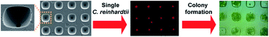
A perforated hemispherical microwell structure is shown to efficiently capture single Chlamydomonas reinhardtii (C. reinhardtii) cells, culture them to form colonies, and retrieve these colonies to serve as seeds for large-scale cultivation. This solution-phase formation and recovery of colonies could overcome the tedious and time-consuming process of selecting colonies from a solid-phase agar plate. The fabricated microdevice was composed of three layers: a top layer consisting of a cell solution for injection and recovery of a microalgal solution, a hemispherical perforated microwell array in the middle, and a bottom layer in which the solution is manipulated by controlling the hydrodynamic force. The microalgal (wild type and hygromycin B-resistant mutant) cells loaded in the top layer rapidly diffused into the microwell holes, and individual such cells were captured with high efficiency (>90%) and within 1 min by applying a withdraw mode in the bottom layer. Single-cell-based cultivation in a medium containing hygromycin B was then performed to generate colonies in the hemispherical microwell. While the wild type cells died, mutant cells resistant to hygromycin B survived well and grew into a colony within 2 days. The produced colonies in the microwells were recovered by applying a release mode in the bottom layer, so that a hydrodynamic force was exerted vertically to push out the colonies through the outlet in 10 s. The recovered cells were cultured on a large scale in medium by using a flask. The recovered C. reinhardtii was confirmed as a hygromycin B-resistant mutant by identifying the hygromycin gene in the polymerase chain reaction (PCR). The microdevice described here could in solution perform single-cell capture, colony formation, and retrieval of colonies for further large-scale cultivation, which could replace tedious and time-consuming solid-phase agar plate processes with a 7-fold reduction in the duration of the process.


Introduction

Sources of energy that are alternatives to fossil fuels have been eagerly sought after, and among them, biological sources such as biomass have been considered promising for producing fuel.1 Chlamydomonas reinhardtii, one of the eukaryotic green algae, has been extensively investigated, and is the most widely used organism that acts as a source of bioenergy for the production of fuels such as hydrogen and biodiesel. The ideal strain of C. reinhardtii should show high photosynthetic efficiency,2 rapid growth rate, and high lipid content. To obtain such a superior microalga, many biologists prepared genetically engineered C. reinhardtii libraries, and screened them to isolate a promising strain.3 However, the conventional process for genetic modification including electroporation or the bead beating method suffers from low efficiency,4 and strain selection based on solid-phase agar plating takes a long time to carry out.5 In particular, agar-plated colony formation requires more than 2 months depending on the microalgal strain, which could be a bottleneck for development of biomass-based energy production. A routine procedure for colony formation and recovery consists of a dispersion of cells on an agar plate at the single-cell level, cultivation to produce a colony, and selection of a colony for large-scale culture in a flask. Since the whole process is carried out on a solid-phase agar plate, the diffusion rate of nutrients and antibiotics to the cells is very limited, resulting in low efficiency for isolating genetically modified C. reinhardtii.

Current advances in microfluidics and lab-on-a-chip technology have yielded excellent performance in chemical and biological analysis, with low sample consumption, high speed, automation, and portability.6–10 A variety of cellular analysis microdevices for studying high-throughput cell culture, single-cell analysis, and cell-to-cell interaction have been reported.11–18

To substitute for the conventional process of agar plating colony formation and retrieval, a microdevice that can handle single cells is required. Since the microfluidic device can be made on a scale similar to that of cells, precise manipulation of cells during cell capture and isolation is possible. The microwell array has been one of the widely used microdevices for single-cell analysis. Rettig et al. reported a polydimethylsiloxane (PDMS) microwell device for trapping cells with high efficiency by controlling the well diameter.19 Liu et al. fabricated a rounded microwell structure which was imprinted from well-ordered polystyrene beads, and using this device enzyme kinetics was studied at the single-cell level.20 Lee et al. developed a microfluidic main channel with small side channels on each side wall, which enables selective cell trapping at lateral microfluidic junctions by fluid suction, and in this way they monitored direct cell–cell communication.21 Although the microdevices described in these reports demonstrated high performance for single-cell manipulation, they were of limited use for single-cell-based culture and recovery.

In this study, we propose a hemispherical perforated microwell structure that has a large hole on the top and a small hole at the bottom. Our unique microwell array design enables us to capture single cells with ease and high efficiency by exerting a hydrodynamic force. In addition, the hemispherical shape serves as a culture chamber, so that single-cell-based colony generation could be conducted. The perforated microwell structure also allowed us to retrieve the produced colonies by applying back-pressure from the bottom. Thus, our methodology can replace the whole agar plate process with a solution phase. We used two types of C. reinhardtii (wild type and a hygromycin B-resistant mutant) to demonstrate our ability to carry out high-throughput screening of genetically modified C. reinhardtii with high rapidity, accuracy and reliability.

Experimental

Chemicals and materials

A positive photoresist (PR) (S1818) and an MF™-CD-26 developer were purchased from Rohm and Haas Electronic Materials Limited Liability Company (USA). A 〈100〉 Si wafer was obtained from iTASCO (Korea). An isotropic wet etching solution was prepared from a mixture of hydrofluoric acid (DC chemical, 50%), nitric acid (Junsei, 70%), and acetic acid (SAMCHUN, 99.5%). An aqueous KOH solution (Sigma-Aldrich 85%) was used as an anisotropic wet etchant. 3-Aminopropyltriethoxysilane (APTES), 3-glycidoxypropyl trimethoxysilane (GPTMS) and hygromycin B were purchased from Sigma-Aldrich (Korea). A PDMS prepolymer and a curing agent (a Sylgard 184 elastomer kit) were purchased from Dow Corning Corporation (USA). An acryl sheet with a thickness of 30 μm was ordered from Sejin T. S. Co., Ltd. (Korea). Primers were made from Integrated DNA Technologies (USA). Vistex 111-50 was ordered from FSI Coating Technologies (USA). Chlamydomonas reinhardtii strain CC-125 (mt + nit1 nit2) was obtained from Chlamydomonas Resource Center (University of Minnesota, USA), and an i-genomic BYF DNA extraction minikit was purchased from iNtRON Biotechnology (Korea). TaKaRa LA Taq with GC buffer was purchased from Takara Korea Biomedical Inc. (Korea). A fluorescence image of C. reinhardtii strain was visualized under a confocal laser microscope (Nikon, ECLIPSE, C1si, Japan).

Fabrication of a hemispherical microstructure

Fig. 1A shows the fabrication scheme for a large-scale single-cell-manipulating microstructure in an acryl sheet. An Si wafer was coated with a 300 nm thick Si3N4 layer and a positive PR, and then a square dot array with dimensions of 20 μm was patterned through a conventional photolithography process. The exposed Si3N4 layer was removed by reactive ion etching (RIE) with CF4 plasma, and the remaining positive PR was cleaned with acetone. An anisotropic wet etching of a Si wafer was performed in a 5 M KOH aqueous solution for 30 min, followed by an isotropic etching for 5 min in a mixture of HF, HNO3 and CH3COOH (the volumes of which were 20, 35 and 55 mL, respectively) to form concave microwells in a Si wafer. After vigorous washing with distilled water and drying, the remaining Si3N4 layer was removed by RIE with CF4 plasma. The resultant Si wafer, which contained concave hemispherical patterns, was used as a template for making a hard Ni mold. Through the electroplating process against the Si wafer, the convex micropatterned Ni mold was fabricated. To transfer the hemispherical micropattern onto the polymer matrix, the acryl sheet was heat-pressed using a Ni mold with a pressure of 25 MPa at 100 °C for 15 min. As a result, the concave micropatterned acrylate sheet was generated. To make the bottom holes on the hemispherical micropattern, the back of the acryl sheet was etched using RIE in O2 plasma. The produced acryl sheet retains a large-area perforated hemispherical microwell structure with a large hole on the top and a small hole at the bottom.
image file: c4ra09730k-f1.tif
Fig. 1 (A) Process used to fabricate a perforated hemispherical microwell. SEM images of a replicated PDMS from a Si wafer (B) after anisotropic wet etching and (C) isotropic wet etching. (D) SEM image of a large-scale hemispherical perforated microwell structure.

An assembled microdevice for manipulation of single C. reinhardtii cells

The 3 cm long × 2 cm wide integrated microdevice that we used for manipulating single C. reinhardtii cells consists of three layers as shown in Fig. 2A. The top layer has a PDMS microfluidic channel (width × length × height = 600 × 21[thin space (1/6-em)]000 × 250 μm) in which C. reinhardtii cells were injected and recovered. The middle layer was the hemispherical microstructure patterned acryl layer. The bottom layer has a PDMS microchannel (width × length × height = 2800 × 9000 × 250 μm), which was connected with control lines on the top layer to change the flow direction of a cell solution in the top layer. The top and bottom PDMS microchannels were fabricated by a conventional soft lithography procedure and aligned perpendicularly to each other. To bond the acryl sheet with the PDMS layers, each layer was exposed to O2 plasma for 2 min to generate hydroxyl groups and oxygen radicals on the surface, and then the PDMS and acryl sheet were immediately immersed in a 2% (v/v) APTES solution and a 2% (v/v) GPTMS solution, respectively, at 70 °C for 60 min. This process produced the terminal amino-functional groups on the PDMS surface and the epoxide groups on the acryl surface. After drying with N2 gas, the functionalized PDMS layers (top and bottom) were permanently bonded with the acryl sheet (middle) at 70 °C for 24 h through the amine–epoxide reaction. Then, the inlet and outlet of the top PDMS layer, and the two control lines of the bottom PDMS layer were connected with syringe pumps.
image file: c4ra09730k-f2.tif
Fig. 2 (A) The entire process for the high-throughput single-cell capture, single-cell-based culture to form colonies, and retrieval of the produced colonies. (B) The bright field, (C) the fluorescence and (D) the merged images showing uniform capture of single C. reinhardtii cells in the perforated hemispherical microwell.

Transformation of C. reinhardtii by electroporation

For nuclear transformation to produce the hygromycin B-resistant mutant, the C. reinhardtii cells were grown in a Tris acetate phosphate (TAP) medium under continuous light irradiation (50 μmol photons per m per s) at 23 °C in a shaking incubator with an agitation rate of 120 rpm until the cell density reached 1 × 10⁶ cells per mL. The cell wall was removed by treatment with autolysin in a TAP medium. Cells were collected by centrifugation and resuspended in a TAP medium containing 40 mM sucrose to make a final cell density of 1 × 10⁸ cells per mL. The transforming DNA fragment including hygromycin B-resistance gene aph7′′ was amplified by PCR from the pHyg3 plasmid using HgF (5′-CAAGCTTCTTTCTTGCGCTATGA-3′) and HgR (5′-AAGCTTCCATGGGATGACGGG-3′) primers under the following conditions: 94 °C for 1 min; then 30 cycles of 94 °C for 30 s, 56 °C for 30 s, and 68 °C for 2 min; and finally 68 °C for 5 min.22 For electroporation, 300 ng of DNA was added to 40 μL of a cell suspension and the mixture was transferred to an electroporation cuvette with a 2 mm gap. An electric pulse of 250 V was applied to the sample for 8 ms using an ECM 830 electroporator (Harvard Apparatus). After electroporation, cells were resuspended in 10 mL of a TAP medium supplemented with 40 mM sucrose and incubated under dim light for 16 h. Transformants were selected on TAP agar plates containing 15 μg mL−1 hygromycin B.

Capture and culturing of single C. reinhardtii cells and retrieval of colonies

Prior to injecting the (wild type and hygromycin B-resistant mutant) C. reinhardtii cells in the top layer, all the microchannels were filled with a Vistex 111-50 solution and incubated at 70 °C for 1 h to make the microchannel surface hydrophilic. In order to capture single C. reinhardtii cells in the perforated hemispherical microwell array, a withdraw mode was set from the control lines of the bottom PDMS layer with a flow rate of 200–400 μL h−1, while the sample fluid in the top PDMS layer was pulled out to the outlet with a flow rate of 100–200 μL h−1. The injected cell concentration was ∼1000 cells per mL. A hydrodynamic force was exerted from top to bottom in the perforated microwells, so single cells were stuck in each well. Once the single C. reinhardtii cells were captured, a TAP medium containing hygromycin B was injected for cultivation. The flow rate of the top and bottom layer was reduced below 50 μL h−1 and the proliferation from the captured single cell was monitored using a confocal laser microscope. Once the C. reinhardtii colonies were formed in the hemispherical microwells, they were released to the outlet of the top layer by applying an infuse mode from the bottom layer with a flow rate of 10 mL min−1.

Gel electrophoresis for identification of the hygromycin B-resistance gene

Collected C. reinhardtii colonies from the microwells were cultured in a T25 flask for more than 2 weeks to obtain a sufficient population of cells. The prepared cells were lysed by an i-genomic BYF DNA extraction minikit to obtain genomic templates. The PCR cocktail was prepared by using a TaKaRa LA Taq with a GC Buffer, and the primers were designed for amplification of a hygromycin B-resistance gene. The PCR was carried out with 12.5 μL of 2X GC buffer, 4 μL of dNTP mixture, 2.25 μL of deionized distilled water, 1 μL of a template solution (1 ng mL−1), 0.25 μL of a TaKaRa LA Taq and 2.5 μL of a forward primer (100 pmol μL−1, 5′-ATGACACAA-GAATCCCTGTTACTT-3′) and 2.5 μL of a reverse primer (100 pmol μL−1, 5′-AGAGGAACTGCGCCAGTTCC-3′). PCR thermal cycling was carried out by an initial activation step at 94 °C for 1 min, 30 amplification cycles of 94 °C for 30 s, 55 °C for 30 s, and 72 °C for 120 s, followed by a final extension step at 72 °C for 5 min. The entire PCR was finished within 2 h. To confirm the PCR products, gel electrophoresis was carried out using a 1% agarose gel in a 0.5X TBE buffer at a voltage of 135 V for 60 min. After separating the PCR products, the gel was incubated with an ethidium bromide staining solution for 30 min and then the product bands were observed using a UV transilluminator.

Results and discussion

Fig. 1A describes the overall scheme for preparing the perforated hemispherical microwell array. This type of microwell structure with open holes would be adequate not only for stabilizing the cells in position during the bioassay process, but also for manipulating the capture and release of single cells as demonstrated below. To achieve such a unique micropattern array, the concave micropatterned Si wafer was fabricated through a combination of anisotropic and isotropic wet etchings. As a first step, the Si wafer was anisotropically etched in an aqueous KOH solution to produce a concave pyramidal structure, which was confirmed by the replication of PDMS from the etched Si wafer (Fig. 1B). Subsequently, the Si wafer was isotropically etched in a mixture of HF, HNO3 and CH3COOH with an etching rate of 2–3 μm min−1. The concave pyramidal microstructure on the Si wafer transformed to the concave Taj Mahal style as shown in the replicated PDMS (Fig. 1C). A Ni mold was fabricated using an electroplating process against the concave Taj Mahal-shaped Si wafer.

The corresponding convex micropattern of the Ni mold was transferred to the acryl polymer sheet by hot embossing. We chose the acryl sheet as a substrate because, after its surface is modified, it easily forms bonds with PDMS, and because the acryl sheet can be dry etched at a relatively uniform rate with O2 plasma. After hot embossing with the convex Ni mold, the back of the acrylate sheet was etched out using RIE in the presence of O2 plasma. The diameter of the bottom hole could be controlled by specifying the etching time, and a 5 μm diameter was patterned with a 45 min etching time (120 W, 100 sccm); this size is smaller than that of a single C. reinhardtii cell. Fig. 1D shows an enlarged and top view of the large-scale hemispherical single-cell capture microarrays that retain a large hole on the top and a small one at the bottom. The funnel shape enables the flow to be controlled vertically by hydrodynamic forces, so that the capture of a single cell per well and the release of the colony could be tuned. In addition, the Taj Mahal shape could be fitted to the cellular morphology, minimizing the physical deformation of the captured cell, and could serve as a culture chamber. Etching carried out only anisotropically produced pyramidal micropatterns, which are not suitable for securing captured cells, and etching carried out only isotropically generated perfectly rounded micropatterns, which make it difficult to control the size of the bottom holes using RIE. On the other hand, Taj Mahal patterns, which were generated by a combination of anisotropic and isotropic wet etchings, contained a sharp tip at the bottom, so the tuning of a bottom hole to be smaller than a single C. reinhardtii cell was feasible.

Fig. 2A describes the entire process for the high-throughput on-chip capture of single cells and formation and retrieval of colonies. The hemispherical microarray patterned acryl layer was bonded with the top and bottom PDMS layers. In the top PDMS layer, the cell solution was loaded in the inlet and recovered in the outlet. In the bottom PDMS layer, two control lines were connected to the microfluidic channel, which functions as a withdrawal or infuse mode for cell manipulation. The top PDMS microfluidic channel was positioned orthogonal to the bottom PDMS channel. When the flow of the bottom layer was withdrawn using a syringe pump with a flow rate of 200–400 μL h−1, the hydrodynamic force was exerted from the top layer to the bottom layer through the hemispherical holes, leading the single cells toward the microhole arrays. In contrast to conventional microwell-based cell capture, which relies on the force of gravity for the settling of cells, our methodology forces individual cells to quickly move into each pocket (within 1 min) and to be fixed in the bottom hole by hydrodynamic forces. Without such a driving force, it is almost impossible to localize the rapidly drifting C. reinhardtii at the single-cell level in a solution phase. Since we controlled the diameter of the top hole (60 μm) and the bottom hole (5 μm), only a single C. reinhardtii cell (10–15 μm diameter) was captured in each microwell and could not pass through the hole. Fig. 2B–D show images of the captured single C. reinhardtii cells in the 3D perforated hemispherical microwell. The red fluorescence derived from chlorophyll of C. reinhardtii was monitored. The single-cell capture was achieved with more than 90% yield, and the cells were uniformly and stably positioned through hydrodynamic control of the fluid from the bottom layer. This stage would thus be equivalent to the single-cell dispersion on an agar plate. After producing a single-cell array, we successively performed the cultivation using two types of C. reinhardtii (wild type and hygromycin B-resistant mutant) cells with and without hygromycin B, which is a well-known inhibitor for protein synthesis (Fig. 2A, middle).

Fig. 3 shows the time-lapse images of the proliferation process starting from a single C. reinhardtii cell in the microwell. The wild-type C. reinhardtii initiated cell division in 12 h in the absence of hygromycin B, and the total population rapidly increased from 12 h to 24 h (Fig. 3A, top panel). However, with the medium containing hygromycin B, the wild-type cell showed no division and suffered from cellular disruption. All green pigmentation of C. reinhardtii cells disappeared after 12 h (Fig. S1). The cell debris was passed through the bottom hole (Fig. 3A, bottom panel). The hygromycin B-resistant mutant C. reinhardtii cells proliferated even with the medium containing hygromycin B (Fig. 3B). Single-cell division of the mutant strain started in 24 h without hygromycin B (Fig. 3B, top panel), while 36 h was necessary for cell division with hygromycin B (Fig. 3B, bottom panel). These results showed that the growth rate of the mutant was much slower than that of the wild type, and the antibiotics could affect the growth rate of the single mutant strain. Interestingly, as the mutant strain underwent cell division, the cells formed a cluster-like morphology rather than completely individual cells. Thus, the single hygromycin B-resistant mutant changed to a single colony in 36 h in the presence of hygromycin B. Images of the resultant colony of the wild type after 24 h and the mutant after 48 h are shown in Fig. 4A and B, respectively. Without hygromycin B, both the wild type and the mutant fully occupied the microwells. When hygromycin B was added, all the single wild-type C. reinhardtii cells died, but the mutant survived and produced a colony (Fig. 4C and D). To mimic the real situation with conventional agar plating, we loaded the mixture of the wild type and mutant, and cultured them from a single-cell array. During cultivation with hygromycin B, the wild-type C. reinhardtii suffered from cell death within 12 h, but the hygromycin-resistant mutant was tolerated and successfully cultured (Fig. 5A–D). The produced colonies were recovered in 60 s by applying the infuse mode in the bottom microfluidic channel (Fig. 2A, right). The collected colonies were resuspended in a large flask, and the cultivation was scaled up (Fig. 5E). We lysed the cultured C. reinhardtii cells, and confirmed the existence of the hygromycin resistance gene (1112 bp) by colony PCR and gel electrophoresis (Fig. 5F). The target gene was clearly verified, suggesting that the collected C. reinhardtii was the hygromycin B-resistance mutant.


image file: c4ra09730k-f3.tif
Fig. 3 (A) Time-lapse images of the cultivation using a single wild-type C. reinhardtii cell without (top panel) and with (bottom panel) hygromycin B. (B) Time-lapse images of the cultivation using a single mutant C. reinhardtii cell without (top panel) and with (bottom panel) hygromycin B.

image file: c4ra09730k-f4.tif
Fig. 4 Colony formation from a single C. reinhardtii cell in each microwell. (A) Formation of wild-type C. reinhardtii colonies in 24 h without hygromycin B. (B) Formation of mutant C. reinhardtii colonies in 48 h without hygromycin B. (C) Cell death of wild-type C. reinhardtii with hygromycin B. (D) Formation of mutant C. reinhardtii colonies in 48 h with hygromycin B.

image file: c4ra09730k-f5.tif
Fig. 5 Cultivation of both the wild type and the mutant from single cells. The mixture of the wild-type and transformed cells was loaded. A mutant strain containing the hygromycin resistance gene survived, while wild-type C. reinhardtii suffered from cell death. Cultivation time: (A) 0 h, (B) 12 h, (C) 24 h and (D) 48 h. (E) Photograph of a large-scale culture using the recovered colonies as seeds. (F) Identification of the hygromycin-resistant gene from the recovered colonies by PCR and gel electrophoresis. L is the DNA ladder.

Our unique platform allows us to monitor the whole process of the patterning of single C. reinhardtii cells, single-cell-based cultivation to form a colony, effects of antibiotics on the cellular growth rate, and the retrieval of the colonies for further large-scale cultivation. Thus, colony formation and recovery based on conventional agar plating could be replaced by the proposed microdevice. The solution phase process in our microdevice should be superior to the method based on the solid-phase agar plate in terms of analysis time and simplicity.

To demonstrate these advantages of our methodology, we compared the time to generate colonies in the proposed microfluidic device with that of the conventional agar plating platform. Fig. 6 shows the time-lapse images of cultivation in the microfluidic device (Fig. 6A) versus an agar plate (Fig. 6B) for 48 h. Initially, the dispersed single cells could be seen in both cases. In the case of the microfluidic cultivation, a TAP medium was continuously injected, so C. reinhardtii cells grew much faster than those of the agar plate due to sufficient nutrient supply. The diffusion rate of the nutrient can be estimated by the Stokes–Einstein equation.

D = kBT/6πηR
where kB is the Boltzmann's constant, T is the temperature in Kelvin, η is the solvent viscosity, and R is the radius of the molecules that diffuse. Since the difference of the viscosity of the solution phase (a TAP medium) and the solid phase (an agar gel) is very large, the nutrient supply to the cells in the microfluidic device would be more efficient than that of the agar plate. Spatial confinement in the solid agar plate also leads to mitotic delay, resulting in a long duration of cell division.18 After 48 h, most of the single cells became colonies in the microdevice, while single C. reinhardtii cells in the agar plate still showed a slow growth rate. The solution-phase colony formation and retrieval in the microdevice could be completed in 48 h, but the solid-phase colony formation and manual colony selection in an agar plate took at least 2–3 weeks, demonstrating an at least 7-fold reduction in the duration of the process using our proposed microdevice.5,23


image file: c4ra09730k-f6.tif
Fig. 6 Comparison of the colony formation time of (A) the microdevice incorporating a perforated hemispherical microwell and (B) the conventional agar plating method. (C) Magnified images of (B). Scale bar: 50 μm.

Conclusions

We successfully demonstrated the ability to capture single cells, and to generate and retrieve colonies for large-scale cultivation in an integrated microdevice that incorporated a perforated hemispherical microwell structure. By controlling the hydrodynamics of the fluid, rapidly moving C. reinhardtii cells could be uniformly and stably localized in each microwell at the single-cell level with high efficiency, and subsequently cultured to form a colony in a short period of time. In addition, the produced colonies were securely recovered for downstream large-scale culture. As a model, a hygromycin B-resistant mutant was isolated from the wild type through the solution-phase colony formation and retrieval process. Compared with the tedious and time-consuming conventional solid-phase agar plating method, our methodology provides more rapid, reliable, and simple tools to select the genetically modified C. reinhardtii cells. Since it is feasible to expand in parallel the hemispherical microarray format, high-throughput screening would be possible regardless of cell type, enabling an acceleration of the process for searching for superior microalgae.

Acknowledgements

This work was supported by the grant from Korea CCS R&D Center (2013M1A8A1040878, 2014M1A8A1049278), and the Engineering Research Center of Excellence Program of Korea Ministry of Science, ICT & Future Planning (MSIP)/National Research Foundation of Korea (NRF) (Grant NRF-2014-009799).

Notes and references

  1. P. M. Schenk, S. R. Thomas-Hall, E. Stephens, U. C. Marx, J. H. Mussgnug, C. Posten, O. Kruse and B. Hankamer, BioEnergy Res., 2008, 1, 20–43 CrossRef PubMed .
  2. R. M. Dent, M. Han and K. K. Niyogi, Trends Plant Sci., 2001, 6, 364–371 CrossRef CAS .
  3. R. Radakovits, R. E. Jinkerson, A. Darzins and M. C. Posewitz, Eukaryotic Cell, 2010, 9, 486–501 CrossRef CAS PubMed .
  4. J. Coll, Span. J. Agric. Res., 2006, 4, 316–330 CrossRef .
  5. R. León, A. Galván and E. Fernández, Transgenic microalgae as green cell factories, Springer Science + Business Media, 2007 Search PubMed .
  6. J. Avesar, T. B. Arye and S. Levenberg, Lab Chip, 2014, 14, 2161–2167,  10.1039/c4lc00013g .
  7. D. D. Carlo and L. P. Lee, Anal. Chem., 2006, 78, 7918–7925 CrossRef .
  8. S. Le Gac and A. van den Berg, Trends Biotechnol., 2010, 28, 55–62 CrossRef CAS PubMed .
  9. S. Lindström and H. Andersson-Svahn, Lab Chip, 2010, 10, 3363–3372 RSC .
  10. R. l. Trouillon, M. K. Passarelli, J. Wang, M. E. Kurczy and A. G. Ewing, Anal. Chem., 2012, 85, 522–542 CrossRef PubMed .
  11. P. Sabounchi, C. Ionescu-Zanetti, R. Chen, M. Karandikar, J. Seo and L. P. Lee, Appl. Phys. Lett., 2006, 88, 183901 CrossRef PubMed .
  12. S. Kobel, A. Valero, J. Latt, P. Renaud and M. Lutolf, Lab Chip, 2010, 10, 857–863 RSC .
  13. D. Di Carlo, N. Aghdam and L. P. Lee, Anal. Chem., 2006, 78, 4925–4930 CrossRef CAS PubMed .
  14. D. Di Carlo, L. Y. Wu and L. P. Lee, Lab Chip, 2006, 6, 1445–1449 RSC .
  15. A. M. Skelley, O. Kirak, H. Suh, R. Jaenisch and J. Voldman, Nat. Methods, 2009, 6, 147–152 CrossRef CAS PubMed .
  16. J. Chung, Y.-J. Kim and E. Yoon, Appl. Phys. Lett., 2011, 98, 123701 CrossRef PubMed .
  17. T. Arakawa, M. Noguchi, K. Sumitomo, Y. Yamaguchi and S. Shoji, Biomicrofluidics, 2011, 5, 014114 CrossRef PubMed .
  18. W. Xi, C. K. Schmidt, S. Sanchez, D. H. Gracias, R. E. Carazo-Salas, S. P. Jackson and O. G. Schmidt, Nano Lett., 2014, 14(8), 4197–4204,  DOI:10.1021/nl4042565 .
  19. J. R. Rettig and A. Folch, Anal. Chem., 2005, 77, 5628–5634 CrossRef CAS PubMed .
  20. C. Liu, J. Liu, D. Gao, M. Ding and J.-M. Lin, Anal. Chem., 2010, 82, 9418–9424 CrossRef CAS PubMed .
  21. P. J. Lee, P. J. Hung, R. Shaw, L. Jan and L. P. Lee, Appl. Phys. Lett., 2005, 86, 223902 CrossRef PubMed .
  22. P. Berthold, R. Schmitt and W. Mages, Protist, 2002, 153, 401–412 CrossRef CAS PubMed .
  23. T. Yamano, H. Iguchi and H. Fukuzawa, J. Biosci. Bioeng., 2013, 115, 691–694 CrossRef CAS PubMed .

Footnote

Electronic supplementary information (ESI) available. See DOI: 10.1039/c4ra09730k

This journal is © The Royal Society of Chemistry 2014
Click here to see how this site uses Cookies. View our privacy policy here.