
 Open Access Article
 This Open Access Article is licensed under a
 Creative Commons Attribution 3.0 Unported Licence
Spectral and luminescent properties of ZnO–SiO2 core–shell nanoparticles with size-selected ZnO cores†
A. E.
Raevskaya
a,
Ya. V.
Panasiuk
a,
O. L.
Stroyuk
*a,
S. Ya.
Kuchmiy
a,
V. M.
Dzhagan
b,
A. G.
Milekhin
cd,
N. A.
Yeryukov
c,
L. A.
Sveshnikova
c,
E. E.
Rodyakina
c,
V. F.
Plyusnin
de and
D. R. T.
Zahn
b
aL.V. Pysarzhevsky Institute of Physical Chemistry of National Academy of Sciences of Ukraine, Kyiv, Ukraine. E-mail: stroyuk@inphyschem-nas.kiev.ua; alstroyuk@ukr.net; Fax: +380-44-525-02; Tel: +380-44-525-02
bSemiconductor Physics, Technische Universität Chemnitz, Chemnitz, Germany
cA.V. Rzhanov Institute of Semiconductor Physics of Siberian Branch of Russian Academy of Sciences, Novosibirsk, Russian Federation
dNovosibirsk State University, Novosibirsk, Russian Federation
eInstitute of Chemical Kinetics and Combustion of Siberian Branch of Russian Academy of Sciences, Novosibirsk, Russian Federation
First published on 18th November 2014
Abstract
Deposition of silica shells onto ZnO nanoparticles (NPs) in dimethyl sulfoxide was found to be an efficient tool for terminating the growth of ZnO NPs during thermal treatment and producing stable core–shell ZnO NPs with core sizes of 3.5–5.8 nm. The core–shell ZnO–SiO2 NPs emit two photoluminescence (PL) bands centred at ∼370 and ∼550 nm originating from the direct radiative electron–hole recombination and defect-mediated electron–hole recombination, respectively. An increase of the ZnO NP size from 3.5 to 5.8 nm is accompanied by a decrease of the intensity of the defect PL band and growth of its radiative life-time from 0.78 to 1.49 μs. FTIR spectroscopy reveals no size dependence of the FTIR-active spectral features of ZnO–SiO2 NPs in the ZnO core size range of 3.5–5.8 nm, while in the Raman spectra a shift of the LO frequency from 577 cm−1 for the 3.5 nm ZnO core to 573 cm−1 for the 5.8 nm core is observed, which can indicate a larger compressive stress in smaller ZnO cores induced by the SiO2 shell. Simultaneous hydrolysis of zinc(II) acetate and tetraethyl orthosilicate also results in the formation of ZnO–SiO2 NPs with the ZnO core size varying from 3.1 to 3.8 nm. However, unlike the case of the SiO2 shell deposition onto the pre-formed ZnO NPs, individual core–shell NPs are not formed but loosely aggregated constellations of ZnO–SiO2 NPs with a size of 20–30 nm are. The variation of the synthetic procedures in the latter method proposed here allows the size of both the ZnO core and SiO2 host particles to be tuned.
Introduction
Among various inorganic semiconductor nanomaterials zinc oxide nanoparticles (NPs) attract constantly high attention due to the promising combination of size-dependent electronic, optical, photochemical, and luminescent properties combined with the availability, a great variety of attainable geometries of ZnO nano-assemblies, low toxicity, etc.1,2 The broad spectrum of applications of ZnO NPs, such as sensors, solar cells, bio-imaging, photocatalysis, UV-shielding, LEDs put forth rigorous requirements for chemical, thermal, and photochemical stability of ZnO NPs, versatility of surface chemistry, control of the ZnO NP size and compatibility of ZnO NPs with water-based bio-environments. Many of these issues can be successfully addressed by combining zinc oxide with silica in the form of guest–host composites and core–shell NPs.Silica shell deposition is usually done in order to achieve stability of ZnO NPs in aqueous environment as well as to inhibit NP growth during thermal treatment.3–6 Routinely, a shell of SiO2 is deposited as a result of hydrolysis of tetraethyl orthosilicate (TEOS) or other siliceous ethers in the presence of pre-formed ZnO NPs.4,5,7–16 Similar stabilization effects are observed for ZnO NPs formed in the presence of pre-formed SiO2 NPs3,17 or much larger sub-micron SiO2 spheres,18 wires19 and tubes,20 or deposited into the pores of mesoporous SiO2 (ref. 21–23) and zeolites.24,25 An alternative way to fabricate silica-encapsulated ZnO NPs is the co-hydrolysis of Zn and Si precursors typically producing SiO2 nano/microspheres incorporating many ZnO NPs.26,27
As a rule, passivation with silica shells results in simultaneous manifold enhancement of the photoluminescence (PL) of ZnO NPs8,18 and the PL quantum yield (QY) of core–shell ZnO–SiO2 NPs which can be as high as 60%.4 Silica-stabilized ZnO NPs characterized by high PL quantum yields and low cytotoxicity can then be used for bio-imaging,6,8,10 light detection,21 for laser,24 LED,15,28 and photocatalysis applications.9,11,13,20,29 In some cases, a dense SiO2 shell is formed on the surface of ZnO NPs to inhibit the photochemical activity of zinc oxide NPs before introducing them into pigments and UV-shielding compositions.5,9,12,16,17,30
Recently we reported a new synthesis of colloidal ZnO NPs in dimethyl sulfoxide (DMSO) using a series of tetraalkyl ammonium hydroxides with alkyl varying from ethyl (Et) to pentyl to hydrolyze Zn(II) acetate (ZnAc2) and demonstrated the feasibility of terminating the growth of ZnO NPs at any desired moment and size by depositing a SiO2 shell on the surface of ZnO NPs by the hydrolysis of TEOS.31 Here, we report a more detailed study of ZnO–SiO2 NPs produced by shell deposition onto zinc oxide NPs as well as by simultaneous hydrolysis of ZnAc2 and TEOS by NEt4OH in DMSO. The paper focuses on the possibilities of varying ZnO core sizes and on the size-dependence of optical properties of the ZnO–SiO2 NPs.
Experimental details
Anhydrous zinc(II) acetate, dimethyl sulfoxide (DMSO), aqueous solution of N(C2H5)4OH (20 w%), tetraethyl orthosilicate, polyvinyl alcohol (PVA) were supplied by Sigma-Aldrich. Colloidal ZnO NPs were synthesized as a result of reaction between Zn(CH3COO)2 (ZnAc2) and tetraethyl ammonium hydroxide (NEt4OH) in DMSO at ambient pressure and temperature. The synthesis is described in details elsewhere.31 In a typical procedure, 0.2 mL 1.0 M ZnAc2 solution in DMSO were diluted in 9.65 mL of DMSO and then 0.15 mL of aqueous 20 w% solution of NEt4OH were rapidly added at vigorous magnetic stirring. Thus, the ratio of [Zn(II)]![[thin space (1/6-em)]](https://www.rsc.org/images/entities/char_2009.gif) :[OH−] was maintained at 1:1 and the total Zn(II) concentration was equal to 2 × 10⁻² M. Here and further in the text and figure captions, the square brackets refer to molar concentration of a compound (ions) placed inside the brackets.
:[OH−] was maintained at 1:1 and the total Zn(II) concentration was equal to 2 × 10⁻² M. Here and further in the text and figure captions, the square brackets refer to molar concentration of a compound (ions) placed inside the brackets.
After the synthesis the colloidal ZnO solutions were subjected to thermal treatment at 60 °C for a various time from 1 to 120 min. Then the further growth of ZnO NPs was quenched by addition of a mixture of 2 × 10⁻² M of TEOS and 2 × 10⁻² M of NEt4OH at vigorous stirring and formation of core–shell ZnO–SiO2 NPs. In separate experiments the TEOS concentration was varied (in the range of 2 × 10⁻³ to 2 × 10⁻¹ M) in the absence or presence of NEt4OH when the concentration of both TEOS and NEt4OH or only NEt4OH were varied at a constant ZnO content to determine an optimal composition of the shell material precursors producing the most stable and luminescent ZnO–SiO2 NPs.
An alternative approach to mixed zinc–silicon oxide NPs consisted in simultaneous hydrolysis (co-hydrolysis) of ZnAc2 and TEOS in DMSO in the presence of NEt4OH. The amount of NEt4OH introduced was calculated as 2 × [ZnAc2] + [TEOS]. In some experiments the concentrations of TEOS and NEt4OH were varied together or separately at a constant ZnAc2 content.
Powder samples of ZnO–SiO2 NPs were prepared via slow evaporation of DMSO at ambient conditions followed by drying at 100–150 °C and, in some experiments, calcination at 500 °C. The PVA films incorporating ZnO–SiO2 NPs were prepared by mixing the corresponding DMSO-based colloids with aqueous 10 w% solutions of PVA. The resulting viscous solution was deposited onto preliminary cleansed glass plates and dried at room temperature for solvent evaporation.
In the experiments on the photochemical stability of ZnO–SiO2 NPs and for acquisition of the photographs of luminescing colloids, powders or films were illuminated by the light from a mercury high-pressure 100 W lamp filtered in the range of 310–390 nm with the intensity of ∼1018 quanta per min per cm2.
Absorption spectra were registered using Specord 220 or HP Agilent 8453 spectrophotometers in 1.0–10.0 mm standard quartz cuvettes using zinc(II) acetate solution in DMSO as a blank reference sample. PL spectra were registered using a Perkin-Elmer LS55 spectrometer or an Edinburgh Instruments FLS920 photon counting system with an excitation wavelength of 320 nm. The latter system was also used to acquire PL decay curves for colloidal solutions. For this purpose an EPLED-320 laser diode (λex = 320 nm, pulse duration 600 ps) was applied. The PLQY Φ was determined using solid extrapure anthracene (Fluka) as a reference standard (Φref = 100%). Colloidal solutions with an optical density exceeding 2 on the excitation wavelength were used for Φ determination to ensure complete light absorption. PL was excited with λex = 320 nm, emitted from a thin surface layer and collected at an angle of 90° with respect to the exciting light beam. Identical measurement conditions (cuvette, slits, spectrum registration rate, etc.) were maintained for the reference and work sample. The PLQY was calculated as ΦZnO = (IZnO/Iref) × Φref, where IZnO and Iref is the integral PL intensity of the sample and reference, respectively. The PL decay curves were approximated by linear combinations of 3 monoexponential functions
FTIR spectra were registered using a Bruker IFS-113V Fourier-transform infra-red (FTIR) spectrometer with a spectral resolution of 2 cm−1. To avoid any influence of substrate IR absorption/reflection, spectra of NPs deposited on silicon substrates covered by a 40 nm Au layer were investigated. For excitation of Raman spectra λex = 325.0 nm of a He–Cd laser was used. The spectra were registered at room temperature using a micro-Raman LabRam HR800 spectrometer. The laser power on the sample was 0.2 mW, the spectral resolution was better than 3 cm−1.
Scanning electron microscopy (SEM) was carried out using a Raith-150 at an acceleration voltage of 10 kV. Transmission electron microscopy (TEM), high-resolution TEM (HRTEM) and selected area electron diffraction (SAED) experiments were carried out on a Philips CM 20 FEG microscope at an accelerating voltage of 200 kV. The hydrodynamic size L and zeta-potential of ZnO and ZnO–SiO2 NPs was determined by dynamic light scattering (DLS) spectroscopy using a Malvern Zetasizer Nano setup. The X-ray diffraction (XRD) analysis was performed using a Bruker D8 Advance diffractometer with Cu Kα irradiation (1.54184 Å) in a Bragg–Brentano geometry in the angle range of 0.4–60° with the scanning rate of 1° min−1. The peak positions were determined with an accuracy of 0.02°.
Results and discussion
As we showed recently,31 the interaction between ZnAc2 and NEt4OH in DMSO results in the formation of colloidal crystalline ZnO NPs that are stable against aggregation without additional stabilizing agents. Ageing of the colloidal solutions at room temperature results in a gradual increase of the zinc oxide absorbance and a red shift of the absorption band edge indicating an increase of both ZnO concentration and the average ZnO NP size. At an elevated temperature these processes occur faster and the changes in size become more pronounced. It was found that the growth of ZnO NPs in wet DMSO can be terminated at any given time by the addition of TEOS as a result of its hydrolysis by the present water and formation of a protective SiO2 shell around ZnO NPs.31Thus, the combination of the techniques for size variation by heating and size stabilization by a shell deposition allows a series of size-selected core–shell ZnO–SiO2 NPs to be produced.
The ZnO–SiO2 NPs produced by a SiO2 shell deposition onto pre-formed size-selected ZnO NPs
Fig. 1a shows the absorption spectra of a series of colloidal ZnO–SiO2 solutions produced by ageing of original ZnO NPs at 60 °C for 1, 5, 15, 60, and 120 min followed by NP growth quenching by TEOS/NEt4OH addition. The position of the absorption band threshold of ZnO NPs, λt, determined as the cross point between the x-axis and the tangent to the linear section of the absorption band edge, is a fundamental characteristic of ZnO NPs which depends on the average NP size d. Deposition of a SiO2 shell does not affect either intensity or the position of the ZnO NP absorption band. | ||
| Fig. 1 Absorption spectra (a), hydrodynamic size distributions (b) and PL spectra (c) of ZnO–SiO2 NPs produced from ZnO NPs subjected to thermal treatment at 60 °C for 1 min (curve 1), 5 min (curve 2), 15 min (curve 3), 60 min (curve 4), and 120 min (curve 5) before TEOS/NEt4OH addition. [ZnO] = 0.01 M, [TEOS] = 0.02 M, [NEt4OH] = 0.04 M. Cuvette – 1.0 mm. Photograph in (a): ZnO–SiO2 colloids with different ageing time (from left to right – from 1 to 120 min) under illumination with UV light (310–390 nm). | ||
The trend of ZnO NP growth in the course of the thermal treatment is corroborated by measurements of the hydrodynamic size L of ZnO–SiO2 NPs using DLS spectroscopy. Fig. 1b and Table 1 show L increasing from 3.6 nm for 1 min thermal treatment to 7.8 nm for prolonged ageing of 120 min. For the former sample of ZnO–SiO2 NPs the mean size d determined from the absorption spectra, 3.5 nm, is remarkably close to the hydrodynamic size L, 3.6 nm, indicating that the SiO2 shell is very thin. It should be noted here that silica particles produced in similar conditions by TEOS hydrolysis in the absence of ZnO NPs are characterized by hydrodynamic sizes of ∼150–160 nm ((ESI), Fig. S1,† curve 1) indicating that ZnO NPs serve as nuclei for silica deposition.
| t, min | E g, eV | d, nm | L, nm | E PL(1), eV | E PL(2), eV | 〈τ〉, μs |
|---|---|---|---|---|---|---|
| a The data for ZnO–SiO2 NPs synthesized by co-hydrolysis of ZnAc2 and TEOS. b Evaluation from XRD data using the Scherrer formula. Errors of determination of Eg, EPL(1), d, and L are ±0.01 eV, ±0.05 nm, ±0.2 nm (±0.5 nm in case of ZnO–SiO2), respectively. [TEOS] = 0.05 M. | ||||||
| 1 | 3.67 | 3.5 (3.4b) | 3.8 | — | 2.32 | 0.78 |
| 5 | 3.55 | 4.0 | 5.0 | 3.55 | 2.29 | 0.79 |
| 15 | 3.49 | 4.3 | 6.5 | 3.50 | 2.25 | 0.87 |
| 60 | 3.39 | 5.3 | 7.0 | 3.41 | 2.20 | 1.12 |
| 120 | 3.36 | 5.8 | 7.8 | 3.36 | 2.15 | 1.49 |
| 1a | 3.89 | 3.1 (3.1b) | ∼15 | — | 2.55 | — |
As the size of ZnO NPs becomes larger the discrepancy between d and L increases up to 2 nm for the sample with 5.8 nm core (Table 1). The divergence between d and L, most probably, reflects thickening of the SiO2 shell as a result of a decrease in the total surface area of ZnO NPs and increase of the TEOS amount available per each ZnO particle.
It was found that colloidal ZnO NPs in DMSO are characterized by small negative zeta-potential of 12–14 mV. Such negative surface charge of ZnO NPs obviously does not impede formation of a SiO2 shell which is most probably facilitated by formation of a thin primary zinc silicate layer, as suggested by IR data (see below). The same low negative zeta-potentials are typical for coated ZnO–SiO2 NPs irrespectively of the coating method.
The X-ray diffraction pattern of ZnO–SiO2 NPs with 3.5 nm core size produced as a powder after complete DMSO evaporation (ESI, Fig. S2,† curve 1) shows several broadened peaks typical for [100], [101], [102], and [110] reflections of the hexagonal zincite modification of zinc oxide (JCPDS card # 36-1451) indicating formation of crystalline ZnO NPs. A halo in the range of 15–30° reflects the presence of amorphous materials that is, most probably, SiO2. Typically, silica forms an amorphous shell in the core–shell ZnO–SiO2 nanostructures prepared by different methods and in a variety of conditions.6,13,27,29 The average size of coherent X-ray diffraction domains in the sample studied and calculated using the Scherrer formula is as small as 3.4 ± 0.1 nm (Table 1) matching closely the size of the ZnO core NPs determined from the absorbance threshold and DLS measurements.
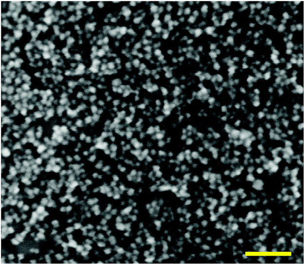
Fig. 2 presents TEM (a) and HRTEM (b) images of ZnO–SiO2 NPs with a 3.5 nm zinc oxide core size produced by 1 min ageing before the silica shell deposition. An inset in Fig. 2a shows that the ZnO–SiO2 NPs are characterized by a size distribution between 2 and 6 nm centered at 4 nm. The crystallinity domains that can be observed in the HRTEM image (Fig. 2b, entoured by yellow circles) have a size of 3.2–3.6 nm with a periodicity of 0.27 nm typical for hexagonal zincite (100) face. The core–shell NP and crystalline core size match closely to the results of estimations based on the absorbance spectra, XRD and DLS. Fig. S3 (ESI†) shows a typical selected area electron diffraction pattern (SAED) of such ZnO–SiO2 NPs. The SAED pattern reveals a set of concentric reflexes that can be indexed as belonging to the hexagonal zincite (JCPDS card # 36-1451) with no admixtures of other phases indicating silica shell to be amorphous.
 | ||
| Fig. 2 TEM (a) and HRTEM (b) images of ZnO–SiO2 NPs produced after 1 min ageing before deposition of a SiO2 shell. The scale bar is 50 nm (a) and 5 nm (b). Inset in (a): size distribution of ZnO–SiO2 NPs. Circles in (b) show several separate ZnO cores. | ||
It was found that wrapping of ZnO NPs into a SiO2 shell imparts them with a perfect immunity to further growth not only in the synthesis conditions, at 60 °C, but also at higher T. The absorption band edge of ZnO–SiO2 NPs with a 3.5 nm zinc oxide core retains unchanged position in the course of the thermal treatment of the colloid at 90–95 °C even for 3–4 h (ESI, Fig. S4†).
The DLS measurements (ESI, Fig. S1†) showed that such treatment is accompanied with a considerable increase of the hydrodynamic size of ZnO–SiO2 NPs from 3.6 nm for the original colloid (Fig. S1,† curve 2) to around 30 nm for the solution heated for 3 h (Fig. S1,† curve 3). Coupled with the constancy of the λt position the fact indicates that the thermal treatment results in a aggregation of individual ZnO–SiO2 NPs.
Scanning electron microscopy of ZnO–SiO2 NPs with 5.8 nm ZnO cores produced after 120 min thermal treatment at 55–60 °C (Fig. 3) shows the presence of separate spherical particles with a size between 5 and 8 nm. This size correlates with the data derived from DLS measurements and shows that individual core–shell ZnO–SiO2 are formed in contrast to loosely aggregated ZnO–SiO2 NPs produced by simultaneous hydrolysis of ZnAc2 and TEOS discussed in the next section.
 | ||
| Fig. 3 SEM image of ZnO–SiO2 NPs of ZnO NPs with an average size of 5.8 nm. The scale bar is 50 nm. | ||
The PL spectra of ZnO–SiO2 NPs reveal two bands, the first one located in the UV range of 350–400 nm and the second one observed in the visible spectral range of 450–700 nm (Fig. 1c). The intensity and maximum position of both PL bands depend considerably on the size of the ZnO core (Table 1). For the 3.5 nm ZnO core the UV band is not developed enough to enable reasonably accurate determination of the position of the band maximum (Fig. 1c, curve 1).
As the size of the ZnO core is increased from 3.5 to 4.0 nm the UV band becomes resolved enough to estimate the band maximum position at 350 nm (EPL(1) = 3.55 eV) perfectly matching the band gap value of these NPs (Table 1). Further increase in the ZnO core size from 4.0 to 5.8 nm is accompanied by a shift of EPL(1) from 3.55 to 3.36 eV, following closely the variation in the band gap derived from UV-vis spectra (Table 1). These facts indicate that the UV band originates from direct radiative electron–hole recombination, and its size variation is a result of electron confinement.3,14,18,19,22,23,26,27,32
The second PL band is characterized by a large Stokes shift of around 200 nm (∼1.25 eV between the absorption threshold and the PL band maximum) and a spectral width of around 160 nm (Fig. 1c), which are typical for the radiative electron–hole recombination with participation of deeply trapped charge carriers.3,14,18,19,22,23,26,27,32 The band maximum position shifts from 490 nm (2.53 eV) to 535 nm (2.32 eV) as the size of ZnO core increases from 3.5 to 5.8 nm indicating that one of the carriers participating in the radiative recombination is free and affected by the spatial confinement. The noticeable increase in the UV band intensity at the simultaneous decrease in the defect-related PL is observed for larger ZnO core size (Fig. 1c). This fact clearly demonstrates that thermal treatment of the ZnO core NPs not only increases the mean NP size, but also enhances their structural perfection by partly annihilating both radiative and non-radiative defect states.
The inset in Fig. 1a shows the photographs of colloidal core–shell ZnO–SiO2 NPs with the core size increasing from 3.5 to 5.8 nm (photograph) illuminated by UV light (310–390 nm). As can be seen, the ZnO–SiO2 NPs with the core size of 3.5–4.0 nm emit quasi-white light which turns into brownish emission as the size of ZnO core is further increased.
The quantum yield of defect-mediated PL of colloidal ZnO–SiO2 NPs depends on the zinc oxide core size and duration of the thermal treatment and is as high as 15% for the smallest ZnO cores. The solvent evaporation from colloids with 3.5–4.0 nm ZnO cores yields yellowish-white-emitting powders which can potentially be used as luminescent fillers for various light-emitting materials. Alternatively, the white-light-emitting ZnO–SiO2 NPs can be incorporated into polyvinyl alcohol films, the PL efficiency of ZnO–SiO2 NPs incorporated into PVA remaining the same as in original colloidal solution. It should be noted that ZnO–SiO2 NPs in the form of colloidal solutions, powders, or components of PVA films demonstrate remarkable photochemical stability retaining constant optical and PL characteristics during 3 h exposure to relatively intense UV light (∼1018 quanta per min per cm2, λ = 310–390 nm).
Deposition of a silica shell onto luminescent semiconductor NPs, including zinc oxide, is a widespread tool of rendering the NPs stable in aqueous media and thus making possible utilization of luminescent NPs in bio-imaging applications.6,8,10 The same trend was observed for the ZnO–SiO2 NPs in DMSO. While unprotected ZnO NPs loose stability and coagulate fast after addition of water, the ZnO–SiO2 colloids can be diluted with water in a broad range of DMSO:water volume ratio – from 1:2 to 1:100 and retain stability for at least two weeks. Fig. S5a (ESI†) shows absorption and PL spectra of ZnO–SiO2 colloid diluted in 20 times by DMSO and water and aged for 2 weeks. The average NP size is the same in both cases (curves 1 and 2) as indicated by identical position of the absorption band edge. The PL band position and width remain also unchanged but PL is quenched by around 40% after 14 day ageing of ZnO–SiO2 NPs in water (compare curves 3 and 4 in Fig. S5a†). Besides water, the ZnO–SiO2 colloids in DMSO can be mixed with a variety of solvents such as acetone, acetonitrile, 2-propanol, toluene, benzene, ethylene glycol, glycerol, etc. Except for glycerol and ethylene glycol, mixing of ZnO–SiO2 colloids in DMSO with other organic solvents is not accompanied by appreciable PL quenching (ESI, Fig. S5b†).
Fig. 4a (curves 1–4) shows kinetic curves of PL decay for colloidal ZnO–SiO2 NPs with different sizes of the zinc oxide core – 3.5, 4.3, 5.3, and 5.8 nm measured near the centre of the defect-related PL band, at 550 nm. The PL decay curves are strongly nonexponential and can be fitted with a linear combination of at least three mono-exponential functions with characteristic time constants of the order of 30–40, 400–500, and 1400–1600 ns with the longest component contribution reaching 70–80%. Such comparatively long life-times are typical for ZnO–SiO2 systems.14,25 The measurements of the PL decay curves in the range of 350–400 nm were hampered by interference of the dispersive medium fluorescence.
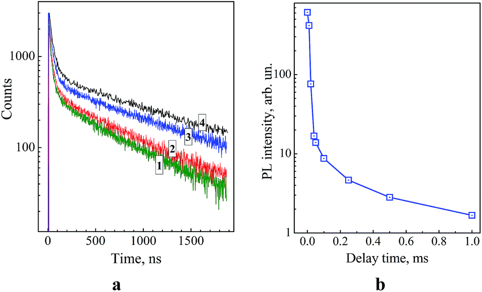 | ||
| Fig. 4 Kinetic curves of PL decay for core–shell ZnO–SiO2 NPs produced from ZnO NPs aged at 60 °C for 1 min (curve 1), 15 min (curve 2), 60 min (curve 3), and 120 min (curve 4) before TEOS/NEt4OH addition. The curves are registered at 550 nm. (b) PL decay of ZnO–SiO2 NPs in the form of dried powder registered in the millisecond time range. | ||
The average radiative life-time of the broad-band emission of ZnO–SiO2 NPs (Table 1) increases from 0.78 μs for the smallest ZnO core (3.5 nm) to 1.49 μs for the largest core (5.8 nm). This fact, along with the attenuation of this band intensity and enhancement of the excitonic PL discussed above, indicates that the thermal treatment at 60 °C noticeably improves the lattice perfection of ZnO NPs. It should be also noted that ZnO and ZnO–SiO2 NPs with the same core size, 5.8 nm, demonstrate similar PL intensity and decay dynamics, indicating that the SiO2 shell does not affect the radiative recombination sites on the surface of ZnO NPs.
It was found that illumination of the ZnO–SiO2 NP powders with the largest core, 5.8 nm, by flashes of UV light (310–390 nm) results in a bluish-green afterglow that can be observed by the eye for 1–2 seconds after the flash. Illumination of colloidal ZnO–SiO2 solutions from which the powders were prepared, in the phosphorescence mode of the luminescence spectrometer showed that PL can be observed even after 1–2 millisecond delay after excitation (Fig. 4b). The spectrum of such long-time PL measured after the 1 ms delay coincides with the stationary PL spectrum indicating that the same type of radiative recombination sites is responsible for the PL in entire measured time range. Similar PL afterglow was also observed earlier for various ZnO–SiO2 heterostructures.14,28
Fig. 5a shows FTIR reflection/absorption spectra of ZnO and ZnO–SiO2 NPs annealed at 300 °C on the surface of silicon. The IR spectrum of ZnO NPs shows characteristic vibrational peaks of ZnO at 410 and 580 cm−1, related to transversal optical (TO) E1 and longitudinal optical (LO) A1/E1 phonons, respectively.33 Another three features observed in the spectrum (670, 850, 1050 cm−1.) are related to molecular vibrations in residual ZnAc2 and NEt4OH.34 In the spectrum of ZnO–SiO2 NPs the ZnO-related bands are preserved and several additional modes appear (Fig. 5a, curve 2), which can be assigned to the SiO2 shell itself or its binding with the ZnO core. Particularly, the broadening and upward shift of the band near 400 cm−1 can be related with influence of shell-induced strain and appearance of Zn–O bond between Zn and O atoms of the shell.
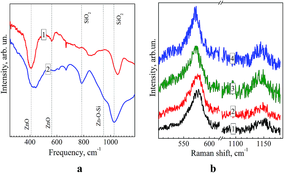 | ||
| Fig. 5 (a) FTIR reflection/absorption spectra of ZnO NPs (curve 1) and core–shell ZnO–SiO2 NPs (curve 2) after deposition on silicon covered with gold and annealed at 300 °C. Dashed lines represent characteristic frequencies of Zn–O, Si–O–Si and Zn–O–Si vibrations (see discussion in the text). (b) Raman spectra of colloidal ZnO–SiO2 NPs prepared from ZnO NPs annealed at 60 °C for 1 min (curve 1), 5 min (2), 60 min (3), and 120 min (4). | ||
The frequency of the Zn–O bond usually occurs at 440–470 cm−1.10 The broad, obviously multicomponent band in the range of 1000–1200 cm−1 is typical for IR spectra of SiO2 and is a superposition of TO and LO components of the asymmetric stretching vibrations.35 The band at 780 cm−1 originates from a symmetric Si–O stretching.35 The shoulder at 950 cm−1 in the FTIR spectrum of ZnO–SiO2 NPs can be assigned to a Zn–O–Si vibration29,35 clearly indicating the formation of a ZnO–silica interface in core–shell ZnO–SiO2 NPs. No Zn–O–Si bond related vibrations were observed in the FTIR reflectance spectrum of annealed mixture of separately prepared ZnO and SiO2 particles, most probably due to a small contact area between zinc oxide NPs and much larger 100–200 nm silica spheres forming in DMSO in the absence of ZnO NPs (see above). The fact additionally confirms formation of a core–shell ZnO–SiO2 structure as a result of TEOS hydrolysis in the presence of ZnO NPs.
A set of FTIR spectra of ZnO–SiO2 NPs with a different size of zinc oxide core – from 3.9 to 5.8 nm is presented in Fig. S6 (ESI†). It can be seen that irrespective of the ZnO core size all the spectra are similar in peak positions and relative intensities indicating no appreciable size dependence of the energy of vibrations active in FTIR spectra.
Fig. 5b shows the Raman spectra of ZnO–SiO2 NPs with a different sizes of the ZnO core – 3.5 nm (curve 1), 4.0 nm (2), 5.3 nm (3), and 5.8 nm (4). All the spectra reveal the characteristic 1LO phonon peak at 573–577 cm−1 and the 2LO overtone at around 1140 cm−1.36 The main LO peak is shifted downward from 577 cm−1 for 3.5–4.0 nm ZnO core samples to 573 cm−1 for bigger 5.3 nm and 5.8 nm zinc oxide cores. A slight narrowing of the LO peak, observed with the increase in the ZnO core size, can be related with the improved crystallinity, in agreement with the PL results discussed above. However, the phonon frequency shift at increasing NP size and/or improved crystallinity should occur towards higher frequencies,33i.e. opposite to that observed in Fig. 4b. Therefore, in order to explain the shift, we assume that NPs may undergo a size-dependent pressure from the SiO2 shell. In particular, the smaller ZnO particles are more compressed. The latter conclusion does not, however, agree with the commonly reported trend for the compressibility of ZnO (as well as of other materials) nanoparticles to decrease with decreasing NP size.37,38 The explanation of the Raman peak shift in our case may, therefore, be found in the different degree of crystallinity of our size-selected ZnO NPs, related with different duration of the thermal treatment. Particularly, the smaller NP sample, grown with shorter thermal treatment time, may possess poorer crystallinity, which also causes the larger Raman peak width (Fig. 5b). This explanation is supported by the fact that solely the phonon confinement does not cause noticeable peak shift and broadening for ZnO NPs in the size range of 3–6 nm.39 In addition, the structural properties or the SiO2 shell may also vary in different samples, leading to a different effect on the vibrational properties of the ZnO core.
The ZnO–SiO2 NPs produced by the simultaneous hydrolysis of ZnAc2 and TEOS in the presence of NEt4OH
Co-hydrolysis of ZnAc2 and TEOS in DMSO in the presence of NEt4OH also results in the formation of stable colloidal ZnO–SiO2 solutions exhibiting the characteristic absorption band of ZnO NPs but shifted to higher energies as compared with the above-discussed core–shell ZnO–SiO2 NPs with the same chemical composition and treatment but synthesized from pre-formed size-selected ZnO cores (compare the first and the last lines in Table 1). The band gap of ZnO–SiO2 NPs with 3.1 nm core, produced by co-hydrolysis followed by the 1 min post-synthesis heating is 3.89 eV. The XRD patterns of the ZnO–SiO2 and ZnO–SiO2 NPs are quite similar (ESI, Fig. S2†). The product of the co-hydrolysis is characterized by a somewhat larger broadening of the reflections corresponding to the coherent diffraction domain size of 3.1 ± 0.1 nm matching closely the estimations made from the absorption spectra. At the same time, the centre of the hydrodynamic size distribution of ZnO–SiO2 NPs produced by co-hydrolysis of ZnAc2 and TEOS is around 15 nm, contrary to 3.6 nm for corresponding ZnO–SiO2 NPs synthesized from the pre-formed 3.5 nm ZnO cores (Table 1).A TEM study of such ZnO–SiO2 NPs (Fig. S7a, ESI†) shows that the NPs are loosely aggregated forming constellations with a broad size distribution which is, most probably, responsible for an increase in the average hydrodynamic size from 3.8 nm for ZnO–SiO2 with a separately prepared ZnO core to around 15 nm for similar NPs produced by co-hydrolysis of ZnAc2 and TEOS (Table 1). Observation of individual ZnO cores by HRTEM is strongly hindered by the presence of SiO2, obviously, due to the electron scattering on amorphous silica shells but nevertheless crystalline domains with a size of 3.0–3.2 nm can be detected in the HRTEM images (Fig. S7b, ESI†) which is in accordance with the ZnO core size estimations made on the basis of XRD and UV-vis absorption spectra of such NPs.
Fig. 6 shows absorption spectra of ZnO–SiO2 colloids synthesized at a constant ZnAc2 concentration and a varied content of TEOS and subjected to a thermal treatment at 60 °C for 5 min. The NEt4OH was introduced in an amount equal to [ZnAc2] + [TEOS]. As can be seen the colloidal solutions containing no TEOS (curve 1) and with [TEOS] = [ZnAc2] have identical absorption threshold and therefore the same NP size indicating that equimolar amount of TEOS with respect to ZnAc2 is not enough to terminate the growth of ZnO NPs during the thermal treatment.
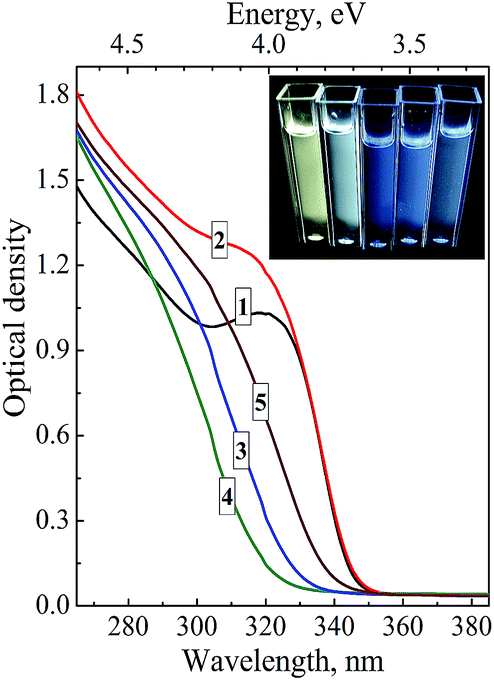 | ||
| Fig. 6 Absorption spectra of ZnO–SiO2 NPs produced at simultaneous hydrolysis of ZnAc2 and TEOS at [ZnAc2] = 0.01 M and [TEOS] = 0 (curve 1), 0.01 M (2), 0.02 M (3), 0.05 M (4), and 0.20 M (5). Inset: photos of luminescing colloidal ZnO–SiO2 solutions with [TEOS] = 0.01, 0.02, 0.08, 0.012, and 0.20 M (from left to right) illuminated by UV light (310–390 nm). Concentration of NEt4OH is 0.02 M + [TEOS]. | ||
An increase in the TEOS concentration to 2 × [ZnAc2] (curve 3) and further to 5 × [ZnAc2] (curve 4) apparently results in the deposition of a protective shell dense enough to prevent annealing and growth of ZnO NPs as evidenced by the increase in the band gap of ZnO NPs (see Table 2). However, at a concentration of TEOS larger than 5 × [ZnAc2] an opposite trend of the band gap narrowing is observed and finally, at 20 × [ZnAc2] (Fig. 6, curve 5) no further changes in the absorbance threshold position can be detected with the band gap levelling at Eg = 3.67 eV, corresponding to d = 3.5 nm (Table 2).
| [TEOS], M | E g, eV | d, nm | L, nm | E PL(2), eV | I PL × 10−4, arb. un. |
|---|---|---|---|---|---|
| a [ZnAc2] = 0.01 M, [NEt4OH] = 0.02 M + [TEOS]. | |||||
| 0 | 3.60 | 3.8 | 4.3 | 2.30 | 6.7 |
| 0.01 | 3.60 | 3.8 | 4.8 | 2.30 | 6.7 |
| 0.02 | 3.78 | 3.2 | 6.0 | 2.38 | 7.5 |
| 0.05 | 3.89 | 3.0 | 14 | 2.63 | 5.3 |
| 0.08 | 3.83 | 3.1 | 22 | 2.62 | 1.6 |
| 0.12 | 3.78 | 3.2 | 25 | 2.67 | 4.5 |
| 0.20 | 3.67 | 3.5 | 28 | 2.45 | 9.8 |
The average hydrodynamic size of colloidal particles in ZnO–SiO2 solutions shows a trend of steady increase, from 4.8 nm at minimal TEOS amount (equal to that of ZnAc2) to 28 nm at [TEOS] = 0.2 M (Table 2 and Fig. S8, ESI†). At the same time, colloidal solutions retain the remarkable stability toward aggregation in the entire range of TEOS concentration studied.
Similar to the non-aggregated ZnO–SiO2 NPs, the products of co-hydrolysis of ZnAc2 and TEOS emit broadband photoluminescence shifted by 1.1–1.4 eV toward lower energy with respect to the absorbance threshold and Eg (Table 2) and varying in colour from yellowish-white to blue (inset in Fig. 6).
The integral PL intensity depends on the ZnO NP size and TEOS amount in an irregular way (Table 2) – it increases from uncoated ZnO NPs to ZnO–SiO2 NPs with the hydrodynamic size L of 6 nm, then starts to fall as L increases to 22 nm. At a higher TEOS content, as the changes of L are already relatively small, the PL intensity increases with the increase in the size of core ZnO NPs and attains the highest value for 28 nm SiO2 particles containing 3.5 nm ZnO NPs.
Conclusions
Deposition of a silica shell onto the surface of ZnO NPs, synthesized in DMSO as a result of interaction between ZnAc2 and NEt4OH, is an efficient tool of terminating the growth of ZnO NPs during the thermal treatment. In this way stable size-selected core–shell ZnO NPs with the core size ranging from 3.5 to 5.8 nm and shell sizes of around 1 nm can be produced. The colloidal core–shell ZnO–SiO2 NPs emit PL bands centred at ∼370 and ∼550 nm originating from the direct radiative electron–hole recombination and defect-mediated electron–hole recombination, respectively. The thermal treatment and growth of the ZnO core size lead to an increase of the first PL band intensity, attenuation of the defect-related emission and growth of the average radiative life-time from 0.78 μs (the core size of 3.5 nm) to 1.49 μs (5.8 nm). The core–shell ZnO–SiO2 NPs can be incorporated into polymer films, e.g. PVA, and dried to powders where nanoparticulate character of ZnO cores is preserved (according to XRD). The DMSO-based colloids can be mixed with a variety of solvents, including water and benzene. The FTIR spectroscopy supports formation of a SiO2 shell on the surface of ZnO NPs and reveals no size dependence of IR spectral features in the core size range of 3.5–5.8 nm. In the Raman spectra, a downward shift of the main LO frequency from 577 cm−1 for 3.5 nm ZnO core to 573 cm−1 for 5.8 nm core is observed indicating compressive stress in smaller ZnO cores induced by SiO2 shell deposition.Simultaneous hydrolysis of ZnAc2 and TEOS in DMSO in the presence of NEt4OH also results in formation of ZnO–SiO2 NPs with the ZnO core size depending on the TEOS/NEt4OH content allowing variation in the range of 3.1–3.8 nm. Measurement of the hydrodynamic size of the co-hydrolysis products coupled with TEM studies suggested that the process results in formation of loosely aggregated constellations of core–shell ZnO–SiO2 NPs as large as 20–30 nm. Therefore, variation of the synthetic procedures in the method proposed here allows to tune both the size of ZnO core NPs and the size of the host SiO2 particles and produce luminescent materials with strong and tunable emission in the visible spectral range.
Acknowledgements
Authors acknowledge financial support of Alexander von Humboldt Foundation, the State Fund for Fundamental Research of Ukraine (Projects #F53.3/019, 49-02-14U), National Academy of Sciences of Ukraine (Joint Projects of NASU and Siberian Branch of RAS # 07-03-12, 14-02-90410R), the Russian Foundation for Basic Research (RFBR, Grants # 13-02-00063, 14-02-90410), Ministry of Education and Science of the Russian Federation, and Cluster of Excellence “MERGE” (EXC 1075). Authors thank Dr S. Schulze (Technische Universität Chemnitz) for TEM measurements, Dr N.D. Shcherban (L.V. Pysarzhevsky Institute of Physical Chemistry of NASU) for XRD data.Notes and references
- Ü. Özgür, Y. Alivov, C. Liu, A. Teke, M. Reshchikov, S. Doğan, V. Avrutin, S. Cho and H. Morkoç, J. Appl. Phys., 2005, 98, 041301 CrossRef PubMed.
- V. Coleman and C. Jagadish, Basic Properties and Applications of ZnO in Zinc Oxide Bulk, Thin Films and Nanostructures: Processing, Properties, and Applications, ed. C. Jagadish and S. Pearton, Elsevier, Amsterdam, 2006 Search PubMed.
- N. Hagura, T. Takeuchi, S. Takayama, F. Iskandar and K. Okuyama, J. Lumin., 2011, 131, 138 CrossRef CAS PubMed.
- N. Hagura, T. Ogi, T. Shirahama, F. Iskandar and K. Okuyama, J. Lumin., 2011, 131, 921 CrossRef CAS PubMed.
- X. Wang, S. Zhou and L. Wu, J. Mater. Chem. C, 2013, 1, 7547 RSC.
- G. Sotiriou, C. Watson, K. Murdaugh, T. Darrah, G. Pyrgriotakis, A. Elder, J. Brain and P. Demokritou, Environ. Sci.: Nano, 2014, 1, 144 RSC.
- P. Sharma, R. Dutta, M. Kumar, P. K. Singh and A. Pandey, J. Lumin., 2009, 129, 605 CrossRef CAS PubMed.
- K. Matsuyama, N. Ihsan, K. Irie, K. Mishima, T. Okuyama and H. Muto, J. Colloid Interface Sci., 2013, 399, 19 CrossRef CAS PubMed.
- I. Siddiquey, T. Furusawa, M. Sato and N. Suzuki, Mater. Res. Bull., 2008, 43, 3416 CrossRef CAS PubMed.
- H. Zhang, H. Xiong, Q. Ren, Y. Xia and J. Kong, J. Mater. Chem., 2012, 22, 13159 RSC.
- I. Siddiquey, T. Furusawa, M. Sato, N. Bahadur, Md. Alam and N. Suzuki, Ultrason. Sonochem., 2012, 19, 750 CrossRef CAS PubMed.
- Z. Cao, Z. Zhang, F. Wang and G. Wang, Colloids Surf., A, 2009, 340, 161 CrossRef CAS PubMed.
- J. Zhai, X. Tao, Y. Pu, X. Zeng and J. Chen, Appl. Surf. Sci., 2010, 257, 393 CrossRef CAS PubMed.
- S. Panigrahi, A. Bera and D. Basak, J. Colloid Interface Sci., 2011, 353, 30 CrossRef CAS PubMed.
- Y. Li, Y. Yang, C. Sun and S. Fu, J. Phys. Chem. C, 2008, 112, 17397 CAS.
- J. Wang, T. Tsuzuki, L. Sun and X. Wang, ACS Appl. Mater. Interfaces, 2010, 2, 957 CAS.
- Z. Cao and Z. Zhang, Appl. Surf. Sci., 2011, 257, 4151 CrossRef CAS PubMed.
- H. Xia and F. Tang, J. Phys. Chem. B, 2003, 107, 9175 CrossRef CAS.
- X. Li, C. Shao, Y. Liu, X. Zhang and S. Hark, Mater. Lett., 2008, 62, 2088 CrossRef PubMed.
- X. Zhang, C. Shao, Z. Zhang, J. Li, P. Zhang, M. Zhang, J. Mu, Z. Guo, P. Liang and Y. Liu, ACS Appl. Mater. Interfaces, 2012, 4, 785 CAS.
- F. Gao, N. Chino, S. P. Naik, Y. Sasaki and T. Okubo, Mater. Lett., 2007, 61, 3179 CrossRef CAS PubMed.
- T. Vaishnavi, P. Haridoss and C. Vijayan, Mater. Lett., 2008, 62, 1649 CrossRef CAS PubMed.
- W. Zhang, J. Shi, L. Wang and D. Yan, Chem. Mater., 2000, 12, 1408 CrossRef CAS.
- C. Bouvy, E. Chelnokov, W. Marine, R. Sporken and B. Su, J. Non-Cryst. Solids, 2009, 355, 1152 CrossRef CAS PubMed.
- J. Shi, J. Chen, Z. Feng, T. Chen, X. Wang, P. Ying and C. Li, J. Phys. Chem. B, 2006, 110, 25612 CrossRef CAS PubMed.
- D. Firmansyah, S. Kim, K. Lee, R. Zahaf, Y. Kim and D. Lee, Langmuir, 2012, 28, 2890 CrossRef CAS PubMed.
- N. Krins, J. Bass, B. Julian-Lopez, P. Evrar, C. Boissiere, L. Nicole, C. Sanchez, H. Amenitsch and D. Grosso, J. Mater. Chem., 2011, 21, 1139 RSC.
- Y. Li, Y. Yang, S. Fu, X. Yi, L. Wang and H. Chen, J. Phys. Chem. C, 2008, 112, 18616 CAS.
- A. Ali, A. Ismail, R. Najmy and A. Al-Hajry, J. Photochem. Photobiol., A, 2014, 275, 37 CrossRef CAS PubMed.
- L. Wang, X. Zhang, Y. Fu, B. Li and Y. Liu, Langmuir, 2009, 25, 13619 CrossRef CAS PubMed.
- Ya. Panasyuk, O. Rayevska, O. Stroyuk, S. Kuchmiy, V. Dzhagan, M. Hietschold and D. R. T. Zahn, Nanotechnol., 2014, 25, 075601 CrossRef PubMed.
- O. Stroyuk, V. Dzhagan, V. Shvalagin and S. Kuchmiy, J. Phys. Chem. C, 2010, 114, 220 CAS.
- N. Ashkenov, B. Mbenkum, C. Bundesmann, V. Riede, M. Lorenz, D. Spemann, E. Kaidashev, A. Kasic, M. Schubert, M. Grundmann, G. Wagner, H. Neumann, V. Darakchieva, H. Arwin and B. Monemar, J. Appl. Phys., 2003, 93, 126 CrossRef CAS PubMed.
- C. Hsieh, J. Chin. Chem. Soc., 2007, 54, 31 CAS.
- K. Queeney, M. Weldon, J. Chang, Y. Chabal, A. Gurevich, J. Sapjeta and R. Opila, J. Appl. Phys., 2000, 87, 1322 CrossRef CAS PubMed.
- K. Alim, V. Fonoberov, M. Shamsa and A. Balandin, J. Appl. Phys., 2005, 97, 124313 CrossRef PubMed.
- V. Panchal, S. Ghosh, S. Gohil, N. Kulkarni and P. Ayyub, J. Phys.: Condens. Matter, 2008, 20, 345224 CrossRef.
- C. Chen, Y. Shi, Y. Zhang, J. Zhu and Y. Yan, Phys. Rev. Lett., 2006, 96, 075505 CrossRef CAS.
- H. Cheng, K. Lin, H. Hsu and W. Hsieh, Appl. Phys. Lett., 2006, 88, 261909 CrossRef PubMed.
Footnote |
| † Electronic supplementary information (ESI) available: Hydrodynamic size distributions of colloidal SiO2 and ZnO–SiO2 nanoparticles, X-ray diffraction patterns of ZnO–SiO2 nanopowders, absorption and photoluminescence spectra of ZnO–SiO2 colloids in different environments, FTIR reflection spectra of size-selected ZnO–SiO2 nanoparticles, TEM and HRTEM images of ZnO–SiO2 NPs. See DOI: 10.1039/c4ra07959k |
| This journal is © The Royal Society of Chemistry 2014 |