Improved electrochemical performance of LiNi0.4Ti0.1Mn1.5O4 as cathode of lithium ion battery by carbon-coating

Yan-Zhang Jina, Yan-Zhuo Lv*a, Yuan Xueb, Jin Wuc, Xiao-Gang Zhangc and Zhen-Bo Wang*b
aCollege of Material Science and Chemical Engineering, Harbin Engineering University, Harbin, 150001 China. E-mail: lvyanzhuo@hrbeu.edu.cn
bSchool of Chemical Engineering and Technology, Harbin Institute of Technology, No. 92 West-Da Zhi Street, Harbin, 150001 China. E-mail: wangzhb@hit.edu.cn
cXi'an Huijie Industrial Co., Ltd., Xi'an, 710116 China

Received 1st August 2014 , Accepted 13th October 2014

First published on 14th October 2014


Abstract

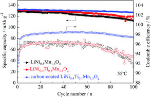
The effects of Ti substitution for Ni, carbon coating on the structure and electrochemical properties of LiMn1.5Ni0.5O4 are studied. LiMn1.5Ni0.5O4, LiNi0.4Ti0.1Mn1.5O4 and carbon-coated LiNi0.4Ti0.1Mn1.5O4 cathode materials have been synthesized by a solid-state reaction using industrial raw materials in bulk scale. X-ray diffraction clearly shows that LiMn1.5Ni0.5O4 has higher crystallinity after Ti doping. Scanning electron microscopy clearly exhibits that Ti doping does not change the basic spinel structure, as well as coated carbon layer covers the surfaces of the LiNi0.4Ti0.1Mn1.5O4 particles. In addition, charge–discharge tests indicate that LiNi0.4Ti0.1Mn1.5O4 sample has higher discharge capacities at the rates of 0.5, 1 and 3 C at 25 °C. It should be noted that carbon-coated LiNi0.4Ti0.1Mn1.5O4 shows higher discharge capacities at the rates of 5, 7 and 10 C at 25 °C as well as various rates for 55 °C. Cyclic performances developed at 25 and 55 °C demonstrate that the capacity retention is remarkably improved compared to the two uncoated samples. The influence of the Ti-doping and carbon-coating on the coulombic efficiency at high temperature (55 °C) has also been investigated. Among the various samples investigated, surface modification with carbon gives an improved coulombic efficiency. The remarkably enhanced electrochemical properties of the carbon-coated sample may be because of the suppression of the solid electrolyte interfacial (SEI) layer development and faster kinetics of both the Li+ diffusion, as well as the charge transfer reaction.


1. Introduction

High energy density and environmentally friendly lithium-ion batteries have attracted significant interest in recent years, especially as devices for electrical vehicles (EVs) and hybrid electrical vehicles (HEVs).1–3 Operating voltage and capacity of the cathode material are two major factors influencing the energy density of lithium-ion batteries.4–6 Therefore, a series of transition metal-substituted spinel lithium manganese oxides (LiMxMn2−xO4; M = Cr, Co, Fe, Ni and Cu) have been synthesized,7–11 which have high-voltage plateaus greater than 4.5 V. Among these doped materials, LiNi0.5Mn1.5O4 has attracted considerable attention because of its good cyclic properties and relatively high capacity, with a plateau at around 4.7 V.10,12–15 More importantly, nickel has been found to be present as Ni2+ in LiNi0.5Mn1.5O4,16 which would suggest the absence of Mn3+, and thereby one would expect the entire capacity to occur in the 5 V region because of the Ni2+/Ni4+ redox couple. However, in practice, the low available capacity at high temperatures17 and poor cycle life at high current densities restrict its commercial applications.18 In recent work,19 it has been reported that the degradation of LiNi0.5Mn1.5O4 in electrochemical performance is mainly because of the decomposition of electrolyte under high potential and side reactions of the active material particles with the electrolyte. The other reason is its intrinsically low electronic conductivity. Based on these studies, it is imperative to overcome these problems to meet the requirement for practical applications in high specific energy density lithium-ion batteries. In recent years, studies on LiNi0.5Mn1.5O4 have been predominantly focused on the improvement in its electrochemical performance using various methods, such as lattice doping with Ru,20 Cr21,22 and Zn23; and surface modification with ZnO24,25 and Al2O3.26

As has been reported,27 Ti4+ doping improves the cyclic performance and discharge capacity of the pristine LiNi0.5Mn1.5O4, because of the Ti–O chemical bond being stronger than Ni–O. Accordingly, it is reasonable to deduce that doping element Ti in LiNi0.5Mn1.5O4 can improve its structural and chemical stabilities. In addition, conductive carbon is characterized by fast electron transport and regarded as an excellent coating material for LiFePO4 in terms of the suppression of SEI formation and the enhancement of electronic conductivity.28,29 Inspired by these works, the structural and electrochemical performance of LiNi0.5−xTixMn1.5O4 (x = 0, 0.1) and carbon-coated LiNi0.4Ti0.1Mn1.5O4 materials has been investigated in the paper, which has not been previously reported.

In the present paper, the aim of this study is to investigate the rate capability and elevated-temperature performances of LiNi0.5Mn1.5O4 synthesized by industrial raw materials (Li2CO3, Ni2O3, electrolytic MnO2, and TiO2). PEG4000 is selected as the carbon source.

2. Experimental

2.1. Material preparation

LiNi0.5−xTixMn1.5O4 (x = 0, 0.1) powders were synthesized by the solid-state reaction method. Stoichiometric amounts of Li2CO3, Ni2O3, electrolytic MnO2 and TiO2 were used as starting materials without further purification. Next, the precursors were ground in a ball-milling machine with anhydrous ethanol as dispersant for 1 h to ensure a complete reaction, followed by drying at 50 °C for 12 h. In order to compensate for the loss of Li at high reaction temperature, approximately additional 5% of Li+ was made up. In the following step, the resulting powders were preheated at 500 °C for 5 h, and then sintered at 850 °C for 12 h to obtain the final LiNi0.5Mn1.5O4 and LiNi0.4Ti0.1Mn1.5O4 particles, in which the cooling rate was set to be 0.5 °C min−1 from 850 °C to 580 °C in flowing air atmosphere. For preparing the carbon-coated sample, the predetermined PEG4000 was mixed with the as-prepared LiNi0.4Ti0.1Mn1.5O4 (part of the above obtained sample) in a solvent mixture of distilled water and ethanol (1[thin space (1/6-em)]:[thin space (1/6-em)]3 by volume). The amount of PEG4000 used corresponded to 3 wt% of the LiNi0.4Ti0.1Mn1.5O4 powders. These mixtures were treated with sonication for 1 h, and stirred by a magnetic stirrer for 4 h. The resulting solvent was evaporated at 50 °C overnight, and then was allowed to dry at 90 °C until a dry powder was obtained. In order to ensure complete adhesion of the carbon particles with the core material LiNi0.4Ti0.1Mn1.5O4, the formed powders were annealed at 350 °C for 1 h under argon to avoid the oxidation of carbon.

2.2. Characterization of material

The crystal structures of the products were characterized by X-ray diffraction (XRD) using a Cu target and recorded with a step of 0.05°. The diffraction patterns were recorded at room temperature in the 2θ range from 10° to 80°. The morphology observations of samples were studied by scanning electron microscopy (SEM) performed on a Quanta-200T.

2.3. Electrochemical properties

The electrochemical performances of each sample were evaluated with a standard CR2025-type coin cell. The cathode was fabricated by blending the prepared powders (80 wt%), acetylene black (10 wt%), and polyvinylidene fluoride (10 wt%) in N-methyl-2-pyrrolidone (NMP). The electrodes were dried under vacuum oven at 120 °C for 12 h, and then punched and weighed. The electrochemical cells were assembled in a glove box under a dry and high purity argon atmosphere. The complete coin cell comprises a cathode, a Celgard 2300 as the separator and a lithium foil anode. To ensure the reliability of the test results of high voltage spinel, the electrolyte was 1 mol L−1 LiPF6 in a mixture of ethylene carbonate (EC)–dimethyl carbonate (DMC) (1[thin space (1/6-em)]:[thin space (1/6-em)]1, v/v). The charge–discharge testing was carried out between 3.50 and 4.95 V using a NEWARE BTS-5 battery test system at 25 and 55 °C, respectively. Rate capability tests were conducted by charging at a constant voltage after the galvanometric charge (0.5, 1, 3, 5, 7 and 10 C rates), and then discharging at the corresponding rate. The cycling performance tests were conducted at a 1 C/5 C (25 °C) and 1 C/1 C (55 °C) charge–discharge rate (1 C = 146.7 mA g−1). Before the electrochemical tests, all of the coin cells were pre-cycled for 3 cycles at 0.5 C to achieve a stable charge state. Cycle voltammetry (CV) and electrochemical impedance spectroscopy (EIS) were carried out using the above cells on a CHI650D electrochemical workstation. Cyclic voltammetry (CV) was conducted in the voltage range from 3.5 V to 5.0 V (versus Li/Li+) at the scanning rate of 0.1 mV s−1. In EIS measurement, the excitation voltage applied to the cells was 5 mV sinusoidal perturbation in the frequency range from 100 kHz to 0.01 Hz at room temperature.

3. Results and discussion

3.1. Structural and morphological characterization

Fig. 1(a) compares the XRD patterns of the LiMn1.5Ni0.5O4, LiNi0.4Ti0.1Mn1.5O4 and carbon-coated LiNi0.4Ti0.1Mn1.5O4 samples. All the diffraction peaks can be indexed as a cubic spinel structure and Fd3m space group. The LiNi0.4Ti0.1Mn1.5O4 and carbon-coated LiNi0.4Ti0.1Mn1.5O4 material have sharper and higher diffraction peaks compared to LiMn1.5Ni0.5O4, indicating that Ti4+ doping endows better crystallinity. However, it can also be observed that there are small peaks at 43.6° in the pattern of products, illustrating that there are secondary phases LixNi1−xO or NiO30,31 indicated by the asterisk. It has been reported that an impurity phase (LixNi1−xO) can be formed at annealing temperatures above 750 °C in LiMn1.5Ni0.5O4.32 Moreover, Amine et al.33 have reported that LiMn1.5Ni0.5O4 loses oxygen and becomes disproportionate to a spinel and rock salt NiO when it is heated above 600 °C. No evidence of diffraction peaks from carbon is observed because of its low quantity and/or amorphous nature (the calcination temperature is as low as 350 °C34). In addition, Ti impurities phase is not observed in our LiNi0.4Ti0.1Mn1.5O4 and carbon-coated LiNi0.4Ti0.1Mn1.5O4 samples. These results indicate that the spinel structure is not affected after doping the LiNi0.5Mn1.5O4 powder with Ti.
image file: c4ra07921c-f1.tif
Fig. 1 XRD patterns of (a) LiMn1.5Ni0.5O4, LiNi0.4Ti0.1Mn1.5O4 and carbon-coated LiNi0.4Ti0.1Mn1.5O4 samples; (b) the enlarged intensity of the (111) peaks.

From the enlargement of the XRD patterns in Fig. 1(b), it can be observed that the diffraction patterns of the LiNi0.4Ti0.1Mn1.5O4 and carbon-coated LiNi0.4Ti0.1Mn1.5O4 shift toward higher angles compared to that of pure LiMn1.5Ni0.5O4, showing that the lattice constants decreases. The reason is that Ti4+ ions enter the crystal lattice of LiMn1.5Ni0.5O4 during the doping process. Hence, it can be concluded that a substitutional compound LiNi0.4Ti0.1Mn1.5O4 has been formed by the interaction of the doped oxide. These variations are attributed to the ionic radius differences among Li+ (0.59 Å), Ni2+ (0.69 Å), Ti4+ (0.605 Å), and Mn4+ (0.53 Å),35 which reveal the incorporation of Ti atoms onto the Ni sites, indicating Ti is successfully introduced into the LiNi0.5Mn1.5O4 matrix structure.

The surface morphologies of the LiMn1.5Ni0.5O4, LiNi0.4Ti0.1Mn1.5O4 and carbon-coated LiNi0.4Ti0.1Mn1.5O4 powders are given in Fig. 2. The LiNi0.5−xTixMn1.5O4 (x = 0, 0.1) and carbon-coated LiNi0.4Ti0.1Mn1.5O4 particles prepared in this work showed primitively good octahedral particles structure, in which Li+ migration is possible through the pathway from tetrahedral to empty octahedral site, satisfying the insertion/extraction of Li into/from LiNi0.5−xTixMn1.5O4. Moreover, the samples consist of particles mainly in the range of 0.3–3.0 μm. Fig. 2(a) and (b) shows that LiMn1.5Ni0.5O4 and LiNi0.4Ti0.1Mn1.5O4 particles have smooth surface facets. The difference of the two samples is that the particle size of LiNi0.4Ti0.1Mn1.5O4 is better-distributed compared to LiMn1.5Ni0.5O4. On the other hand, the surface of the coated LiMn1.5Ni0.5O4 is covered with small particles that mainly consist of carbon, as showed in Fig. 2(c). The conductive carbon layer can not only avoid the direct contact between the active cathode material and the electrolyte, but provide pathways for electron transfer.


image file: c4ra07921c-f2.tif
Fig. 2 SEM images of samples: (a) LiMn1.5Ni0.5O4; (b) LiNi0.4Ti0.1Mn1.5O4; (c) carbon-coated LiNi0.4Ti0.1Mn1.5O4.

3.2. Electrochemical characterization

The charge–discharge profiles of the LiMn1.5Ni0.5O4, LiNi0.4Ti0.1Mn1.5O4 and carbon-coated LiNi0.4Ti0.1Mn1.5O4 samples at 25 °C are presented in Fig. 3. All the curves show a flat voltage plateau at around 4.7 V corresponding to Ni2+/Ni4+ redox process and a small plateau at around 4.0 V corresponding to Mn3+/Mn4+ redox process. The presence of the plateau corresponds to lithium-ion insertion into the 8a tetrahedral sites of the cubic spinel structure. The plateau at around 4.0 V is attributed to the reduction of Mn4+ to Mn3+ involving lithium-ion insertion into 16c octahedral sites of the spinel structure, which will result in a cubic to tetragonal phase transition.
image file: c4ra07921c-f3.tif
Fig. 3 Charge and discharge profiles with various charge rates (0.5, 1, 3, 5, 7 and 10 C) followed by a constant voltage charge and discharging at the corresponding rate (25 °C): (a) LiMn1.5Ni0.5O4; (b) LiNi0.4Ti0.1Mn1.5O4; (c) carbon-coated LiNi0.4Ti0.1Mn1.5O4.

From Fig. 3, the discharge specific capacity of Ti-free LiMn1.5Ni0.5O4 can reach 125.7, 125.0, 118.7, 114.6, 107.8 and 98.6 mA h g−1 at the rates of 0.5, 1, 3, 5, 7 and 10 C, respectively (Fig. 3(a)). Moreover, the discharge specific capacity of LiNi0.4Ti0.1Mn1.5O4 could deliver 135.3, 134.8, 130.2, 126.9, 122.3 and 116.6 mA h g−1 at the rates of 0.5, 1, 3, 5, 7 and 10 C, respectively (Fig. 3(b)). For the sample carbon-coated LiNi0.4Ti0.1Mn1.5O4, the discharge specific capacity is 134.0, 132.5, 129.8, 128.1, 124.4 and 119.4 mA h g−1 at the rates of 0.5, 1, 3, 5, 7 and 10 C, respectively (Fig. 3(c)). The carbon-coated LiNi0.4Ti0.1Mn1.5O4 sample shows an improved discharge capacity compared to carbon-coated LiMn1.5Ni0.5O4 found in the report,36 which suggests that the present synthesis process is effective. Therefore, a great enhancement in rate performance can be obtained through the carbon coating LiNi0.4Ti0.1Mn1.5O4 method.

In comparison of Fig. 3(a) with Fig. 3(b) and (c), the discharge specific capacity increases after the Ti4+ doping at various discharge rates, meaning that the polarization is notably reduced by the Ti4+ doping, which is beneficial for high discharge capacity. This behavior can be understood as follows: the presence of appropriate amounts of Ti atoms favors crystal growth, probably by releasing microstrains caused by lattice defects. In addition, the Ti substitution leads to a progressive broadening and, hence, a decrease in the average domain size. The latter effect can be explained similarly by the difference between the Ti4+ and Ni4+ ionic radii.

Furthermore, it can be determined that the discharge specific capacity of LiNi0.4Ti0.1Mn1.5O4 is higher than that of carbon-coated LiNi0.4Ti0.1Mn1.5O4 at relatively low rates (0.5, 1 and 3 C). It is worth noting that the carbon-coated LiNi0.4Ti0.1Mn1.5O4 sample has a higher discharge specific capacity compared to LiNi0.4Ti0.1Mn1.5O4 at the rates of 5, 7 and 10 C. The improved discharge capacities at high rates can be attributed to the higher electronic conductivity of carbon compared to that of LiNi0.4Ti0.1Mn1.5O4. The carbon phase provides faster pathways for electron transfer, facilitating the electronic connection among LiNi0.4Ti0.1Mn1.5O4 particles and thereby improving the high rate capability.

In order to examine the effectiveness of Ti4+ doping and carbon coating on improving the rate capability of the cathode material at high temperature (55 °C), the discharge specific capacity at different discharge rates is also investigated and represented in Fig. 4.


image file: c4ra07921c-f4.tif
Fig. 4 Charge and discharge profiles with various charge rates (0.5, 1, 3, 5, 7 and 10 C) followed by a constant voltage charge and discharging at the corresponding rate: (a) LiMn1.5Ni0.5O4 at 55 °C; (b) LiNi0.4Ti0.1Mn1.5O4 at 55 °C; (c) carbon-coated LiNi0.4Ti0.1Mn1.5O4 at 55 °C.

As shown in Fig. 4, it can be clearly seen that the discharge capacities of LiMn1.5Ni0.5O4 are enhanced after Ti4+ doping at high temperature (55 °C). It is considered that the faster Li+ ion diffusion in the LiNi0.4Ti0.1Mn1.5O4 electrode result in the improvement of the rate capability. More importantly, the discharge specific capacities (131.8, 131.2, 129.1, 125.0, 117.6 and 105.6 mA h g−1) of carbon-coated LiNi0.4Ti0.1Mn1.5O4 sample are higher than those of LiNi0.4Ti0.1Mn1.5O4 sample (131.0, 130.6, 127.7, 121.8, 113.5 and 104.7 mA h g−1) at corresponding discharge rates (0.5, 1, 3, 5, 7 and 10 C), demonstrating that the surface modification with carbon can make the electrochemical insertion/extraction process of Li+ ion more reversible at the high temperature (55 °C).

Fig. 5 shows the cycling performances of the LiMn1.5Ni0.5O4, LiNi0.4Ti0.1Mn1.5O4 and carbon-coated LiNi0.4Ti0.1Mn1.5O4 cells at 5 C. The initial discharge capacities of the three samples are 121.7, 124.2 and 127.1 mA h g−1, respectively. After 1000 cycles, the capacity retention of the samples at 5 C is 80.6%, 87.2% and 91.5% of their initial discharge special capacity, respectively. It is demonstrated that the cycling capability of LiMn1.5Ni0.5O4 is remarkably improved after Ti element doping, which is associated with the fact that the chemical bond of Ti–O is stronger than that of Ni–O, leading the structure to be stable between charge and discharge cycles process. Furthermore, carbon-coated LiNi0.4Ti0.1Mn1.5O4 displays relatively remarkable cycling stability compared to the fade seen with the LiNi0.4Ti0.1Mn1.5O4 sample, particularly at the discharge later stage, which can be attributed to the carbon coating layer preventing the dissolution of LiNi0.4Ti0.1Mn1.5O4 materials from the electrolyte.


image file: c4ra07921c-f5.tif
Fig. 5 Cycling performances of the LiMn1.5Ni0.5O4, LiNi0.4Ti0.1Mn1.5O4 and carbon-coated LiNi0.4Ti0.1Mn1.5O4 samples charged/discharged with a constant current of 1 C/5 C at 25 °C.

The cycle performances of LiMn1.5Ni0.5O4, LiNi0.4Ti0.1Mn1.5O4 and carbon-coated LiNi0.4Ti0.1Mn1.5O4 cells at 55 °C are shown in Fig. 6. As illustrated, the initial discharge specific capacity of the three samples is 128.2, 130.5 and 132.1 mA h g−1 at 1 C, respectively, indicating that the capacity differences are small among the three samples. Nevertheless, with increasing the cycle number, the pristine LiMn1.5Ni0.5O4 and LiNi0.4Ti0.1Mn1.5O4 suffer from significant polarization increase and capacity fading. The increased polarization may be due to the possible dissolution of the spinel into the electrolyte and electrolyte decomposition at high temperature. Furthermore, the decomposition products can coat on the surface of the electrodes and hinder lithium transport, leading to increased polarization.


image file: c4ra07921c-f6.tif
Fig. 6 Cycling performances of the LiMn1.5Ni0.5O4, LiNi0.4Ti0.1Mn1.5O4 and carbon-coated LiNi0.4Ti0.1Mn1.5O4 samples charged/discharged with a constant current of 1 C/1 C at 55 °C.

On the contrary, the carbon-coated LiNi0.4Ti0.1Mn1.5O4 electrode displays a greatly improved cyclic performance with a discharge capacity of 126.9 (96.1% of its initial capacity) after 100 cycles. The improvement in the cyclic performance should be related to increase in conductivity and the decrease in electrolyte oxidation caused by the carbon coating.

Coulombic efficiency is a key index for evaluating the stability of the electrolyte that is working with the LNMO cathode. To investigate the possible decomposition of the electrolyte at high temperature (55 °C), the coulombic efficiency values of the three samples with cycle number are plotted in Fig. 7. Clearly, the efficiency value changes in the following order: LiMn1.5Ni0.5O4 ≈ LiNi0.4Ti0.1Mn1.5O4 < carbon-coated LiNi0.4Ti0.1Mn1.5O4. This indicates that the oxidation of the electrolyte in the LiMn1.5Ni0.5O4/Li and LiNi0.4Ti0.1Mn1.5O4/Li cells is considerably more severe compared to the carbon-coated LiNi0.4Ti0.1Mn1.5O4/Li cell. From this result, it is considered that carbon coating is an effective method to improve the coulombic efficiency of LNMO materials. It is noted that there is no significant influence of the Ti doped LiMn1.5Ni0.5O4 on coulombic efficiency at 55 °C.


image file: c4ra07921c-f7.tif
Fig. 7 Coulombic efficiencies of the LiMn1.5Ni0.5O4, LiNi0.4Ti0.1Mn1.5O4 and carbon-coated LiNi0.4Ti0.1Mn1.5O4 samples charged/discharged with a constant current of 1 C/1 C at 55 °C.

The CV curves of the LiMn1.5Ni0.5O4, LiNi0.4Ti0.1Mn1.5O4 and carbon-coated LiNi0.4Ti0.1Mn1.5O4 after 1000 cycles at 5 C, conducted at a rate of 0.1 mV s−1, are shown in Fig. 8. The peaks in the CV curves from three samples correspond to the oxidation of Mn3+, Ni2+ and Ni3+. It can be seen that sample carbon-coated LiNi0.4Ti0.1Mn1.5O4 has greater peak current densities compared to LiMn1.5Ni0.5O4 and LiNi0.4Ti0.1Mn1.5O4, indicating its superior performance at high discharge current rate. This result is consistent with that of our above-mentioned cycling performance experiments (Fig. 5). Moreover, the difference (ΔEp) in peak potentials between the redox peaks of sample carbon-coated LiNi0.4Ti0.1Mn1.5O4 (0.17 V) is considerably smaller compared to samples LiMn1.5Ni0.5O4 (0.22 V) and LiNi0.4Ti0.1Mn1.5O4 (0.20 V), which indicates faster lithium insertion/extraction kinetics and higher reversibility of the electrode reaction in the former.37


image file: c4ra07921c-f8.tif
Fig. 8 Cyclic voltammograms of the LiMn1.5Ni0.5O4, LiNi0.4Ti0.1Mn1.5O4 and carbon-coated LiNi0.4Ti0.1Mn1.5O4 electrodes recorded after 1000 cycles at 25 °C.

Fig. 9 shows the A.C. impedance spectra of the LiMn1.5Ni0.5O4, LiNi0.4Ti0.1Mn1.5O4 and carbon-coated LiNi0.4Ti0.1Mn1.5O4 electrodes cells before and after 1000 cycles at 5 C. A potentiostatic step of 1–3 h is performed to stabilize the potential after activating or cycling, followed by the impedance measurement that is carried out at open circuit. As shown in Fig. 9, the EIS of the cell consists of two parts, a semicircle at high and medium frequency, as well as a sloping line at low frequency. The depressed semicircle reflects the interface resistance, including surface layer, as well as charge transfer reaction; the sloping line at low frequency range is related to the solid-state diffusion of Li+ ions in the active materials.38


image file: c4ra07921c-f9.tif
Fig. 9 Electrochemical impendence spectroscope curves of the LiMn1.5Ni0.5O4, LiNi0.4Ti0.1Mn1.5O4 and carbon-coated LiNi0.4Ti0.1Mn1.5O4 electrodes recorded before and after 1000 cycles at 25 °C.

As can be seen in the figure, the impedance of sample carbon-coated LiNi0.4Ti0.1Mn1.5O4 (20 Ω, 62 Ω) is smaller compared to LiMn1.5Ni0.5O4 (41 Ω, 114 Ω) and LiNi0.4Ti0.1Mn1.5O4 (37 Ω, 113 Ω) before and after 1000 cycles at 5 C, especially after 1000 cycles. In addition, the Warburg parameters are summarized in Table 1, presenting that the samples LiNi0.4Ti0.1Mn1.5O4 and carbon-coated LiNi0.4Ti0.1Mn1.5O4 have smaller Warburg values before and after 1000 cycles. Accordingly, it can be inferred that the two samples have lower lithium diffusion resistance compared to LiNi0.5Mn1.5O4, which is beneficial to the insertion/removal of lithium in the lattice of the spinel oxide, thereby improving the electrochemical performance.

Table 1 Warburg parameters calculated from equivalent circuit
Samples Before cycling After 1000 cycles
LiNi0.5Mn1.5O4 0.391(Ω) 0.496(Ω)
LiNi0.4Ti0.1Mn1.5O4 0.344(Ω) 0.444(Ω)
Carbon-coated LiNi0.4Ti0.1Mn1.5O4 0.333(Ω) 0.428(Ω)


According to the analysis of Manthiram,39 the variations in the electrolyte resistance among all three electrodes can be neglected. Consequently, the results indicate the suppression of the development of the SEI layer and reduction of the charge transfer resistance of LiNi0.4Ti0.1Mn1.5O4 after the surface modification with carbon protecting layer. However, the impedance differences between LiMn1.5Ni0.5O4 and LiNi0.4Ti0.1Mn1.5O4 are similar before and after 1000 cycles, and demonstrate that there is a little influence in the electrode resistance after Ti-doping. In addition, a significant increase of interface resistance for the two samples after 1000 cyclings may be relative to the electrolyte decomposing and the formation of a more resistive surface film.

4. Conclusions

Doping the spinel LiMn1.5Ni0.5O4 and coating LiNi0.4Ti0.1Mn1.5O4 cathode material with a small amount of Ti4+ and conductive carbon have been successfully realized with TiO2 and carbonization of PEG4000, respectively. The Ti-doped LiMn1.5Ni0.5O4 and carbon-coated LiNi0.4Ti0.1Mn1.5O4 electrodes exhibit considerably enhanced rate capability and rate cycling performance compared to the Ti-free LiMn1.5Ni0.5O4 at 25 and 55 °C. Furthermore, the discharge capacities of LiNi0.4Ti0.1Mn1.5O4 are higher compared to carbon-coated LiNi0.4Ti0.1Mn1.5O4 at relatively low rates (0.5, 1 and 3 C) at 25 °C. Interestingly, the carbon-coated LiNi0.4Ti0.1Mn1.5O4 sample has higher discharge capacities compared to LiNi0.4Ti0.1Mn1.5O4 at the rates of 5, 7 and 10 C rates at 25 °C. In addition, the carbon-coated LiNi0.4Ti0.1Mn1.5O4 exhibits considerably more excellent cycling stability, higher discharge capacities and coulombic efficiency compared to the LiMn1.5Ni0.5O4 and LiNi0.4Ti0.1Mn1.5O4 samples at high temperature (55 °C). The improvement in the high rate capability and cycle performance of the carbon coated LiNi0.4Ti0.1Mn1.5O4 can be attributed to the acceleration of electron transfer and the suppression of side reactions by the carbon surface modification.

Acknowledgements

We acknowledge the Natural Science Foundation of Heilongjiang Province of China (B201201), the National Natural Science Foundation of China (21203040), China postdoctoral science foundation (Grant no. 2014M561357), the Fundamental Research Funds for the Central Universities (HEUCF201403018), the National Natural Science Foundation of China (Grant no. 21273058), China postdoctoral science foundation (Grant no. 2012M520731), Heilongjiang post-doctoral financial assistance (LBH-Z12089) for their financial support.

References

  1. J.-M. Tarascon and M. Armand, Nature, 2001, 414, 359–367 CrossRef CAS PubMed.
  2. A. S. Arico, P. Bruce, B. Scrosati, J.-M. Tarascon and W. V. Schalkwijk, Nat. Mater., 2005, 4, 366–377 CrossRef CAS PubMed.
  3. X. Huang, M. Lin, Q. Tong, X. Li, Y. Ruan and Y. Yang, J. Power Sources, 2012, 202, 352–356 CrossRef CAS PubMed.
  4. D. Liu, J. Hamel-Paquet, J. Trottier, F. Barray, V. Gariepy, P. Hovington, A. Guerfi, A. Mauger, C. M. Julien, J. B. Goodenough and K. Zaghib, J. Power Sources, 2012, 217, 400–406 CrossRef CAS PubMed.
  5. M. S. Whittingham, Chem. Rev., 2004, 104, 4271–4301 CrossRef CAS.
  6. G. He, Y. Li, J. Li and Y. Yang, Electrochem. Solid-State Lett., 2010, 13, A19–A21 CrossRef CAS PubMed.
  7. W. K. Zhang, C. Wang, H. Huang, Y. P. Gan, H. M. Wu and J. P. Tu, J. Alloys Compd., 2008, 465, 250–254 CrossRef CAS PubMed.
  8. T. F. Yi and Y. R. Zhu, Electrochim. Acta, 2008, 53, 3120–3126 CrossRef CAS PubMed.
  9. S. Patoux, L. Sannier, H. Lignier, Y. Reynier, C. Bourbon, S. Jouanneau, F. L. Cras and S. Martinet, Electrochim. Acta, 2008, 53, 4137–4145 CrossRef CAS PubMed.
  10. Q. Zhong, A. Bonakdarpour, M. Zhang, Y. Gao and J. R. Dahn, J. Electrochem. Soc., 1997, 144, 205–213 CrossRef CAS PubMed.
  11. T. Nakamura, H. Demidzu and Y. Yamada, J. Phys. Chem. Solids, 2008, 69, 2349–2355 CrossRef CAS PubMed.
  12. H. S. Fang, Z. X. Wang, B. Zhang, X. H. Li and G. S. Li, Electrochem. Commun., 2007, 9, 1077–1082 CrossRef CAS PubMed.
  13. S. H. Oh, S. H. Jeon, W. I. Cho, C. S. Kim and B. W. Cho, J. Alloys Compd., 2008, 452, 389–396 CrossRef CAS PubMed.
  14. Y. Z. Lv, Y. Z. Jin, Y. Xue, J. Wu, X. G. Zhang and Z. B. Wang, RSC Adv., 2014, 4, 26022–26029 RSC.
  15. Y. Xue, Z. B. Wang, F. D. Yu, Y. Zhang. and G. P. Yin, J. Mater. Chem. A, 2014, 2, 4185–4191 CAS.
  16. K. Amine, H. Tukamoto, H. Yasuda and Y. Fujita, J. Power Sources, 1997, 68, 604–608 CrossRef CAS.
  17. D. W. Shin and A. Manthiram, Electrochem. Commun., 2001, 13, 1213–1216 CrossRef PubMed.
  18. H. L. Wang, H. Xia, M. O. Lai and L. Lu, Electrochem. Commun., 2009, 11, 1539–1542 CrossRef CAS PubMed.
  19. J. Liu and A. Manthiram, J. Electrochem. Soc., 2009, 156, A833–A838 CrossRef CAS PubMed.
  20. H. L. Wang, H. Xia, M. O. Lai and L. Lu, Electrochem. Commun., 2009, 11, 1539–1542 CrossRef CAS PubMed.
  21. T. A. Arunkumar and A. Manthiram, Electrochim. Acta, 2005, 50, 5568–5572 CrossRef CAS PubMed.
  22. D. Q. Liu, Y. H. Lu and J. B. Goodenough, J. Electrochem. Soc., 2010, 157, A1269–A1273 CrossRef CAS PubMed.
  23. J. Liu and A. Manthiram, J. Electrochem. Soc., 2009, 156, A66–A72 CrossRef CAS PubMed.
  24. Y. K. Sun, K. J. Hong, J. Prakash and K. Amine, Electrochem. Commun., 2002, 4, 344–348 CrossRef CAS.
  25. Y. K. Sun, C. S. Yoon and I. H. Oh, Electrochim. Acta, 2003, 48, 503–506 CrossRef CAS.
  26. J. S. Kim, C. S. Johnson, J. T. Vaughey, S. A. Hackney, K. A. Walz, W. A. Zeltner, M. A. Anderson and M. M. Thackeray, J. Electrochem. Soc., 2004, 151, A1755–A1761 CrossRef CAS PubMed.
  27. M. Lin, S. H. Wang, Z. L. Gong, X. K. Huang and Y. Yang, J. Electrochem. Soc., 2013, 160, A3036–A3040 CrossRef CAS PubMed.
  28. Y. H. Huang, H. B. Ren, Z. H. Peng and Y. H. Zhou, J. Power Sources, 2010, 195, 610–613 CrossRef CAS PubMed.
  29. S. T. Myung, S. Komaba, N. Hirosaki, H. Yashiro and N. Kumagai, Electrochim. Acta, 2004, 49, 4213–4222 CrossRef CAS PubMed.
  30. Q. Zhong, A. Bonakdarpour, M. Zhang, Y. Gao and J. R. Dahn, J. Electrochem. Soc., 1997, 144, 205–213 CrossRef CAS PubMed.
  31. Y. K. Sun, C. S. Yoon and I. H. Oh, Electrochim. Acta, 2003, 48, 503–506 CrossRef CAS.
  32. T. A. Arunkumar and A. Manthiram, Electrochim. Acta, 2005, 50, 5568–5572 CrossRef CAS PubMed.
  33. K. Amine, H. Tukamoto, H. Yasuda and Y. Fujita, J. Electrochem. Soc., 1996, 143, 1607–1613 CrossRef CAS PubMed.
  34. Q. Cao, H. P. Zhang, G. J. Wang, Q. Xia, Y. P. Wu and H. Q. Wu, Electrochem. Commun., 2007, 9, 1228–1232 CrossRef CAS PubMed.
  35. R. D. Shannon, Acta Crystallogr., Sect. A: Cryst. Phys., Diffr., Theor. Gen. Crystallogr., 1976, 32, 751–767 CrossRef.
  36. T. Y. Yang, N. Q. Zhang, Y. Lang and K. N. Sun, Electrochim. Acta, 2011, 56, 4058–4064 CrossRef CAS PubMed.
  37. Y. J. Zhu and C. S. Wang, J. Phys. Chem. C, 2011, 115, 823–832 CAS.
  38. D. Aubarch, J. Power Sources, 2000, 89, 206–218 CrossRef.
  39. J. Liu and A. Manthiram, Chem. Mater., 2009, 21, 1695–1707 CrossRef CAS.

This journal is © The Royal Society of Chemistry 2014
Click here to see how this site uses Cookies. View our privacy policy here.