Recent advances in porous graphene materials for supercapacitor applications
Xiong Zhang,
Haitao Zhang,
Chen Li,
Kai Wang,
Xianzhong Sun and
Yanwei Ma*
Institute of Electrical Engineering, Chinese Academy of Sciences, Beijing 100190, P. R. China. E-mail: ywma@mail.iee.ac.cn; Fax: +86 10 82547137; Tel: +86 10 82547129
First published on 3rd September 2014
Abstract
Driven by the environmental problems and energy crisis, the development of clean and renewable energy materials as well as their devices is urgently demanded. Supercapacitors, also called electrochemical capacitors, which store energy using either ion adsorption or fast surface redox reactions, are supposed to be a promising candidate for alternative electrical energy storage devices due to their high power density, exceptional cycle life, and low maintenance cost. The performance of supercapacitors is highly dependent on the properties of electrode materials. Graphene based materials exhibit great potential application for supercapacitors because of their unique structure and excellent intrinsic physical properties. Introducing porous structures to graphene is an effective strategy to obtain high surface area and high specific capacitance. In this review, we provide a brief summary of the recent developments about the synthesis and application of porous graphene materials for supercapacitors.
1. Introduction
Recently, there has been increasing worldwide demand for the development of alternative energy techniques with higher efficiency and sustainability due to the rapid depletion of fossil fuels and increasingly worsened environmental pollution and global warming. However, power production from sustainable energy resources, including solar, wind, and geothermal energies, is not always coincident with energy demand. For example, implementation of solar or wind energy causes big challenges to power grid management and grid stability because of the large fluctuations in electricity generation that are completely decoupled from the actual energy demand.1 Therefore, the development of large-scale energy-storage systems is very important to resolve this problem. Pumped hydro, flywheels, compressed air energy storage (CAES), superconducting magnetic energy storage (SMES), hydrogen storage, and electrochemical energy storage are usually-proposed alternative and/or competitive solutions for storing energy.2 Among them, electrochemical energy storage devices, such as batteries and electrochemical capacitors (ECs), are becoming leading electrical energy storage (EES) technologies today. Fig. 1 shows the Ragone plot for various electrical energy storage devices.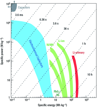 | ||
| Fig. 1 Ragone plots for various electrical energy storage devices. Times shown are the time constants of the devices, obtained by dividing the energy density by the power. Reproduced with permission from ref. 3, Copyright 2008 NPG. | ||
Supercapacitors, also called electrochemical capacitors, have attracted intense attentions because of their higher power densities than batteries and higher energy densities than conventional dielectric capacitors. With high power capability at relatively high energy densities, exceptional cycle life and reliability, supercapacitors have been used in a variety of applications ranging from power electronics, and computer memory backup systems, to large scale transport systems including subway trains and buses, and to energy storage at intermittent generators including windmills, and smart grid applications.4 The fast charge/discharge characteristics and long cycle life of supercapacitors are particularly well suited for recycling energy from repetitive motion (e.g. automotive braking, elevator operation, seaport rubber-tired gantry crane) that would otherwise be wasted, leading to the improved energy efficiency.5 In a hybrid power system, supercapacitors can be combined with batteries or fuel cells in order to enhance the system lifetime and increase the overall efficiencies.6,7 Supercapacitors can also be used as uninterruptible power supplies (UPS) in the industry and load-leveling to provide high quality power, which can greatly reduce economic losses resulted by power disruptions.8 Many excellent reviews about the fundamental considerations of supercapacitors can be found in the literatures.3,9–12
General electric first patented a low voltage electrolytic capacitor in 1957. Later, the Standard Oil of Ohio (SOHIO) Company invented a device that stored energy by the electric double layer (EDL) mechanism in 1966. Following the commercial introduction by NEC in 1978 under license from SOHIO, supercapacitors have evolved through several generations of designs.13,14 Today, there are a number of manufacturers producing supercapacitors, such as Maxwell, NESSCAP, Nippon ESMA, Ioxus and Cap-XX, and so on. However, the energy density of most commercially available supercapacitors (less than 10 W h kg−1) is still significantly lower than batteries. The electrode materials are usually considered to play the most important role in the performance of supercapacitors.
Graphene, a single layer of sp2 hybridized carbon atoms arranged in a hexagonal lattice, has emerged as one of the most attractive carbon allotropes for energy storage applications in recent years due to its unique structure and properties. It has a large theoretical specific surface area (2630 m2 g−1), high intrinsic carrier mobility (2 × 105 cm2 V−1 s−1), excellent thermal conductivity (∼5000 W m−1 K−1), high Young's modulus (∼1.0 TPa), good optical transmittance (∼97.7%), and ultrahigh electrical conductivity at room temperature (106 S cm−1).15–19 Graphene can be prepared by various approaches, including mechanical cleavage of graphite with a Scotch tape,20 epitaxial growth on metal surfaces or single-crystal SiC,21,22 chemical vapor deposition (CVD),23–25 liquid phase exfoliation,26,27 chemical reduction,28–33 thermal reduction,34,35 electrochemical synthesis,36–38 and high energy ball milling.39–42 The application of graphene material as the supercapacitor electrode material was first explored by Ruoff and co-workers in 2008, in which the reduction of graphene oxide (GO) by using hydrazine hydrate exhibited specific capacitances of 135 and 99 F g−1 in aqueous and organic electrolytes, respectively.43 However, graphene sheets tend to form irreversible agglomerates or even restack to form graphite due to the interlayer strong π–π stacking and van der Waals interactions among the graphite single layers, resulting in a dramatic decrease of the surface area and a portion of graphene surfaces practically inaccessible for electrolyte ions.
Making graphene into porous structures is an effective strategy to prevent the agglomerates of graphene nanosheets and to obtain graphene materials with high surface area and high specific capacitance. In this review, we mainly focus on the synthetic approaches of porous graphene materials, based on the strategies of chemical activation, template approach, and self-assembly of graphene nanosheets. Furthermore, the application of porous graphene materials for supercapacitor is also summarized.
2. Supercapacitors: principle and characteristics
2.1. Theoretical background
The main energy storage of supercapacitors originates from the reversible reaction on the surface of electrode materials, including charge separation and faradic redox reaction at the electrode/electrolyte interface.44,45 Because “surface charge storage” does not require bulk ionic diffusion within the inner crystalline framework of electrode materials, supercapacitors can offer ultrafast charge/discharge rates (i.e., high power density), but relatively poor specific capacitance (i.e., low energy density) compared with batteries.46,47 Therefore, many efforts have been devoted to improve the capacitance and energy density.The electrode/electrolyte interface can be regarded as a conventional dielectric capacitor, and the capacitance C is defined by eqn (1):
 | (1) |
 | (2) |
The energy density (E) of a capacitor is expressed by eqn (3), in which V is the charging potential:
 | (3) |
When the stored energy is released through discharge of the capacitance, the maximum power (Pmax) is expressed by eqn (4)
 | (4) |
Supercapacitors can be classified into two categories based on the energy storage mechanism.48,49 One is the electrochemical double layer capacitor (EDLC), in which no electrochemical reaction is involved in the electrode material during the charging and discharging processes, while only pure physical charge accumulation occurs at the electrode/electrolyte interface. The other type is the faradaic capacitor (FC), in which the electrode material store and release charges by electrochemical redox reactions during the charging and discharging processes.
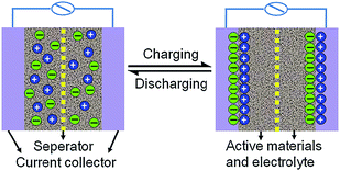 | ||
| Fig. 2 Charge storage mechanism of EDLC. Reproduced with permission from ref. 51, Copyright 2013 Elsevier. | ||
It should be noted that only the surface accessible to electrolyte ions can contribute to charge storage; therefore, optimization of pore size, pore structure, surface properties and conductivity of the electrode materials are desired. This storage mechanism allows very fast energy uptake and delivery and high stability of EDLCs during millions of charge/discharge cycles.
where C is the capacitance of the pseudo-capacitor, q is the quantity of charge, and V is the potential.
The main difference between pseudo-capacitance and EDL capacitance lies in the fact that pseudo-capacitance is faradaic in origin, involving fast and reversible redox reactions between the electrolyte ions and electro-active species on the electrode surface. The typical electrode materials include conducting polymers and transition metal oxide and hydroxide.
When a potential is applied to a FC, fast and reversible faradaic reactions (redox reactions) take place on the electrode materials and involve the transport of charge across the double layer, similar to the charging and discharging processes occurred in batteries, resulting in faradaic current passing through the supercapacitor cell.44 Three types of faradaic processes occur at FC electrodes:
(1) reversible adsorption of active species on the surface of electrode,
(2) redox reactions of transition metal oxides or hydroxides,
(3) reversible electrochemical doping/dedoping of conductive polymer based electrodes.
It has been demonstrated that the electrochemical processes occur both on the surface and in the bulk near the surface of the solid electrode, which can increase the specific capacitance of supercapacitors.52 Therefore, FCs can provide much higher energy density compared with EDLCs. However, FCs usually suffer from relatively lower power density than EDLCs because the redox electrodes usually have poor electrical conductivity and faradaic processes are normally slower than non-faradaic processes. In addition, they often endure poor stability during cycling owe to redox reactions.
Besides, hybrid supercapacitors with an asymmetrical electrode configuration (e.g. one electrode utilizing EDL mechanism while the other consists of faradaic capacitance material) have been extensively studied recently to utilize the advantages of both electrode materials to improve overall cell voltage, energy, and power densities. With respective to this hybrid supercapacitor, both electrical double-layer capacitance and faradaic capacitance mechanisms work simultaneously, but usually one of them is dominant.
2.2. Electrode materials
Among various carbon materials, graphene is a unique and attractive electrode material because of its peculiar structure and excellent properties. The theoretical specific surface area of graphene is as high as 2623 m2 g−1, which is twice larger than that of single-walled carbon nanotubes (CNTs) and much higher than that of most carbon black and activated carbons.68 Therefore, graphene is a promising candidate to deliver high electrochemical double layer capacitance. The interfacial double-layer capacitance on one side of a single graphene sheet is about 21 μF cm−2; thus, the theoretical maximum gravimetric specific capacitance of graphene is approximately 550 F g−1.69 Graphene materials can be obtained at relatively low costs in large scale from graphite as the precursor. The superior electron mobility of graphene facilitates charge transfer during charge/discharge processes, which is beneficial for improving the performance of supercapacitors. The high mechanical, thermal and chemical stabilities of graphene also enhance its cycle stability. Thus graphene is considered as a very promising candidate to replace activated carbons as the electrode materials in high-performance supercapacitors. Fig. 3 shows that 2D graphene layer can be regarded as the basic building block for carbon materials of all other dimensionalities, i.e. 0D fullerene, 1D nanotubes, and 3D graphite.
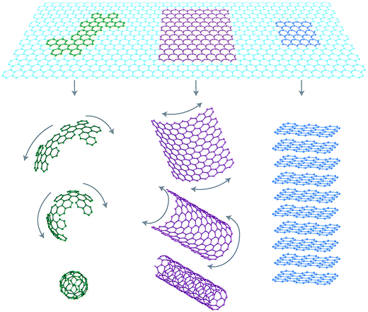 | ||
| Fig. 3 2D Graphene building block for carbon materials with different dimensionalities. Reproduced with permission from ref. 15, Copyright 2007 NPG. | ||
It is well-known that carbon materials have excellent cyclic stability as supercapacitor electrodes, whereas degradation of conducting polymers often occurs less than a thousand of cycles due to stress destroy caused by the doping/de-doping (intercalation/deintercalation) of ions.86 Although higher specific capacitance may be achieved by increasing the doping level of polymers, the accompanying volume change ascribed to more counter ion insertion/de-insertion is supposed to be harmful to the cycle performance. An effective strategy is to form conducting polymers composites with carbon materials to improve the capacitive performance of conducting polymers.
However, metal oxides/hydroxides may not be adopted as commercial supercapacitor electrodes due to the following issues.
(1) Except for RuO2, most metal oxides/hydroxides possess very poor electric conductivity, which increases both the sheet resistance and the charge transfer resistance of the electrode, and especially causes a large IR drop at a large current density.136 Thus the poor power density and the rate capability of metal oxides/hydroxides hinders their practical application.
(2) The internal strain in metal oxides/hydroxides during the charge-discharge processes gives rise to large volume change, leading to poor cycle stability.
(3) It is difficult to design and tailor the surface area, pore distribution and porosity of metal oxides/hydroxides.
As described above, either metal oxides/hydroxides or conducting polymers, if used alone, can't meet the requirements for practical purposes. Thus, it is very necessary to develop high-performance electrode materials for next-generation supercapacitors. Graphene based materials exhibit great potential for application in supercapacitors thanks to their superior intrinsic physical properties. The fabrication of graphene with porous structures is an effective strategy to obtain graphene materials with large surface areas and high electrochemical performance. The following sections will mainly focus on the recent progress of porous graphene and their applications in supercapacitors.
3. Preparation of porous graphene as supercapacitor electrodes
According to the definition of the International Union of Pure and Applied Chemistry (IUPAC), micropores mean the diameter of pores are less than 2 nm, while macropores are pores with a diameter larger than 50 nm, and mesopores are in between.137 It has been recognized that macropores facilitate the penetration and wetting of electrolyte ions to the interior surface and hence improve the rate capability and cycle stability of the electrodes, while mesopores provide a large accessible surface area for ion transport/charge storage, and micropores contribute to increasing the specific surface area (SSA) and specific capacitance.138–141 Several methods have been developed to prepare porous graphene materials, mainly including chemical activation, template approach, and self-assembly of graphene nanosheets.3.1. Chemical activation
The chemical activation process consists of the heat-treatment of a mixture of graphene-based precursor and activating agent at a temperature around 450–900 °C.142–145 KOH, H3PO4 and ZnCl2 are most commonly used for chemical activation. KOH acts as an oxidant, whereas H3PO4 and ZnCl2 act as dehydrating agents.146,147 Chemical activation is an effective method to produce porous graphene materials without the assistance of templates. Experimental data for supercapacitors prepared with porous activated graphene-based materials (mostly chemical activation with KOH) are listed in Table 1.| Material | Surface area (m2 g−1) | Electrolyte | Capacitancea (F g−1) | Ea (W h/kg) | Pa (kW kg−1) | Ref. |
|---|---|---|---|---|---|---|
| a The maximum value.b Values of capacitance for the three-electrode cell system. | ||||||
| Activated MEGO | 2400 | BMIM BF4/AN | 166 | ∼70 | ∼250 | 142 |
| 3100 | EMIM TFSI | 200 | — | — | ||
| Activated MEGO | 3100 | BMIM BF4/AN | 172 | — | — | 143 |
| Activated reduced graphene oxide films | 2400 | 1 M KOH | ∼300 | ∼18 | — | 144 |
| 1 M TEA BF4/AN | 120 | 40 | 500 | |||
| N-Doped activated MEGO | 1929 | 6 M KOH | 420 | — | — | 148 |
| Activated sMEG-O | 3290 | EMIM TFSI/AN | 174 | 74 | 338 | 149 |
| Activated porous graphene nanoribbons | 1249 | EMIM BF4 | 130 | 55.2 | — | 150 |
| Activated nitrogen-doped graphene | 555 | 1 M KOH | 132.4b | — | — | 151 |
| Activated graphene | 1315 | 1 M H2SO4 | ∼240 | — | — | 152 |
| Activated graphene-incorporated nitrogen-rich carbon composite | 1646 | 6 M KOH | 300 | 8.4 | — | 153 |
| Porous graphene/activated carbon composite | 2106 | 6 M KOH | 210 | — | — | 154 |
| 1 M TEA BF4/PC | 103 | 22.3 | — | |||
| Activated carbon/graphene composites | 2566 | 6 M KOH | 334 | ∼10 | — | 155 |
| Graphene–activated carbon composite | 798 | 6 M KOH | 122 | 6.1 | — | 156 |
| EMIM BF4 | 179 (80 °C) | 99.2 | 20 | |||
| Nitrogen-doped porous graphene/carbon composite | 1882.3 | 1 M H2SO4 | 405b | — | — | 157 |
| Activated 3D porous graphene | 3523 | TEA BF4/AN | 202 | 51 | 109 | 158 |
| EMIM BF4 | 231 | 98 | 137 | |||
| Activated microporous carbon nanoplates | 2557.3 | H2SO4 | 264 | — | — | 159 |
| BMIM BF4/AN | 168 | 133 | 217 | |||
| Activated graphene-like carbon nanosheets | 2287 | BMPY TFSI | ∼160 | ∼40 | 77 | 160 |
| Porous graphene-like nanosheets | 1874 | 6 M KOH | 276 | 9.58 | 7.1 | 161 |
| 1 M TEA BF4/PC | 196 | 54.7 | ∼30 | |||
| CO2-activated macroscopic graphene | 829 | 1 M H2SO4 | 278.5b | — | — | 162 |
Ruoff and co-workers reported a facial activation process of microwave-exfoliated GO (MEGO) and thermally exfoliated GO with KOH (Fig. 4a), to achieve a specific surface area value up to 3100 m2 g−1, a high electrical conductivity of ∼500 S m−1, and a low oxygen and hydrogen content (the C/O atomic ratio of up to ∼35).142 These electronic microscopy images clearly indicate that MEGO was etched in the activation process and a three dimensional (3D) distribution of micro- and meso pores was generated with a size distribution between ∼1 and ∼10 nm in the resulting materials (Fig. 4b–e). The two-electrode symmetrical supercapacitor cells on the basis of a-MEGO (SSA ∼2400 m2 g−1) and 1-butyl-3-methyl-imidazolium tetrafluoroborate/acetonitrile (BMIM BF4)/AN electrolyte was constructed and measured. A specific capacitance of 166 F g−1 was obtained at a current density of up to 5.7 A g−1 (Fig. 4f and g). Under the working voltage of 3.5 V, the energy density was calculated to be ∼70 W h kg−1, and the power density was also very high at ∼250 kW kg−1. Moreover, the a-MEGO showed outstanding cycling stability. After 10000 constant current charge/discharge cycles at a current density of 2.5 A g−1 in BMIM BF4 electrolyte, 97% of its capacitance was retained. By using this activation process that has already been commercially demonstrated for activated carbons (ACs), the scale up of producing activated-graphene-based materials for supercapacitors may be realized in a short period.
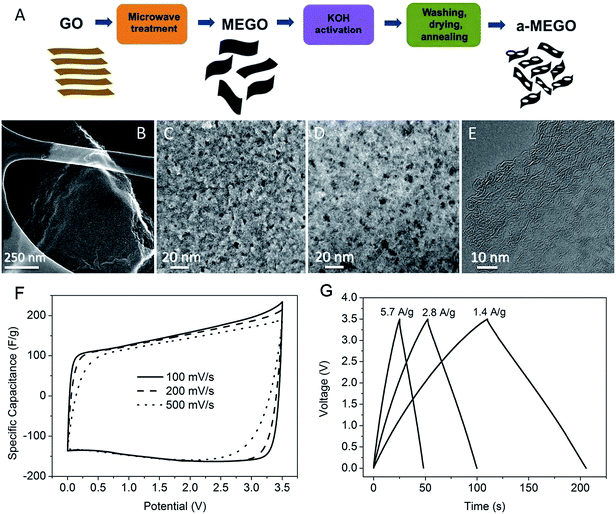 | ||
| Fig. 4 Porous graphene-based electrode materials prepared by activation of microwave-exfoliated GO. (A) Schematic showing the microwave exfoliation/reduction of GO and the following chemical activation of MEGO with KOH. (B) Low-magnification SEM image of a 3D a-MEGO fragment. (C) High-resolution SEM image of a different sample region. (D) Annular dark field scanning transmission electron microscopy (ADF-STEM) image of the same area as in (C), acquired simultaneously. (E) High-resolution phase contrast electron micrograph of the thin edge of an a-MEGO fragment. (F) Cyclic voltammetry (CV) curves of a-MEGO (SSA ∼2400 m2 g−1) for different scan rates. (G) Galvanostatic charge/discharge curves of a-MEGO under different constant currents. Reproduced with permission from ref. 142, Copyright 2011 AAAS. | ||
Ruoff and co-workers further investigated the influence of activation parameters such as the temperature and amount of KOH during the synthesis of a-MEGO on the specific surface area (SSA) of a-MEGO and electrochemical capacitance of a-MEGO electrodes.143 At 800 °C and with KOH/MEGO mass ratio of 6.5, a maximum specific surface area of 3100 m2 g−1 was obtained and a high specific capacitance of 172 F g−1 was measured in a two-electrode cell with a-MEGO electrodes in BMIM BF4/AN electrolyte. Increasing the activation temperature from 600 °C, both the BET SSA and the specific capacitance increased, while they decreased when the activation temperature was up to (or higher than) 800 °C at a constant KOH/MEGO ratio of 6.5 (Fig. 5a). The lower BET SSA and the specific capacitance values at 900 and 1000 °C were due to excess carbonization and collapse of the porous structure. Under the activation temperature of 800 °C, the BET SSA and specific capacitance peaked at a KOH/MEGO loading ratio of 6.5; while loading beyond a ratio of 9, the nonconductive samples with very small carbon content were obtained (Fig. 5b).
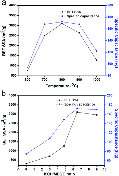 | ||
| Fig. 5 (a) Effect of activation temperature on BET SSA and specific capacitance of a-MEGO, at a constant KOH/MEGO ratio of 6.5; (b) effect of activation KOH/MEGO ratio on BET SSA and specific capacitance of a-MEGO, at a temperature of 800 °C.143 Reproduced with permission from ref. 143, Copyright 2012 Elsevier. | ||
Subsequently, Ma and co-workers developed a route of chemical activation from noncovalent functionalized graphene with KOH to prepare a graphene–activated carbon composite (GAC) with a high specific surface area.156 It is clearly observed that the KOH activated method can create micropores or mesopores in the activated carbon covered on graphene. Hence part of the surface of graphene sheets with a few layers is exposed because of etched activated carbon. Simultaneously the pores in the activated carbon also increase its SSA. In addition, the generation of gas in the activated process also prevents severe agglomeration of graphene sheets to some extent. As a result, the SSA of the final product greatly increases to 798 m2 g−1. The two-electrode symmetrical coin-size capacitor cells were assembled by using 6 M KOH aqueous solution and 1-ethyl-3-methylimidazolium tetrafluoroborate (EMIM BF4) as the electrolytes, respectively. The resulting graphene–activated carbon composite shows a good capacitance of 122 F g−1 and energy density of 6.1 W h kg−1 in 6 M KOH electrolyte. Moreover, the supercapacitor exhibits maximum energy densities of 52.2 and 99.2 W h kg−1 in EMIM BF4 electrolyte at room temperature and 80 °C, respectively (Fig. 6). It is worth noted that the energy density in ionic liquid electrolyte at 80 °C exceeds that at room temperature, indicative of extraordinarily fast ion transport even for a large molecule such as EMIM BF4 at a high temperature.
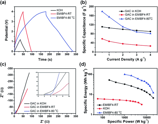 | ||
| Fig. 6 Properties of GAC supercapacitors. (a) Charge/discharge curves at 1 A g−1, (b) rate capability, (c) electrochemical impedance spectroscopy (EIS) plots and its magnification in high frequency in the inset, (d) Ragone plots of GAC in KOH at RT, EMIM BF4 at RT and EMIM BF4 80 °C.156 Reproduced with permission from ref. 156, Copyright 2013 RSC. | ||
Recently, Chen and co-workers reported that porous 3D graphene-based bulk materials were synthesized by hydrothermal polymerization/carbonization of the mixture of GO and industry carbon sources such as biomass, phenol–formaldehyde (PF), and polyvinyl alcohol (PVA), and subsequently followed by chemical KOH activation (Fig. 7a).158 Various structural and morphology analyses demonstrated that these materials consist of almost entirely defected/wrinkled single layer graphene nanosheets (Fig. 7b–e). The as-prepared porous graphene-based materials simultaneously showed excellent bulk conductivity (up to 303 S m−1) and ultrahigh SSA (up to 3523 m2 g−1), with the pore size in the mesopore size range. Meanwhile, those materials exhibited a high specific capacitance of 202 F g−1 in 1 M tetraethylammonium tetrafluoroborate in AN (TEA BF4/AN) and 231 F g−1 in EMIM BF4 electrolyte systems (Fig. 7f and g), corresponding to the gravimetric energy densities as high as 51 and 98 W h kg−1 based on the total weight of active material, respectively. The excellent performance for supercapacitor was attributed to the high accessible SSA and rational distribution of pore sizes of 3D graphene-based bulk materials.
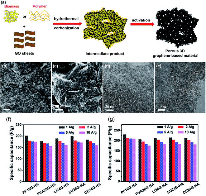 | ||
| Fig. 7 (a) A schematic show of the simple and green process of synthesizing porous 3D graphene-based materials. (b) Low magnification and (c) high-resolution SEM images of products from the mixtures of PF and GO with optimized ratios, which exhibited sponge-like morphology and porous structure. (d) Low magnification and (e) high-resolution TEM images of products from the mixtures of PF and GO with optimized ratios, which also showed a dense 3D pore structure with highly curved or wrinkled surface. Galvanostatic charge/discharge test results of supercapacitors based on the optimized porous 3D graphene-based materials in (f) 1 M TEA BF4/AN and (g) neat EMIM BF4 electrolytes under different current densities. Reproduced with permission from ref. 158, Copyright 2013 NPG. | ||
Physical activation is also a conventional technology to achieve microporosity in porous carbons by enlarging the surface area.146,163 Park and co-workers prepared CO2-activated macroscopic graphene architectures with trimodal pore systems that consist of 3D inter-networked macroporosity arising from self-assembly, mesoporosity which is derived from the intervoids of nanosheets, and microporosity through CO2 activation at 900 °C (Fig. 8a–d).162 The existence of micropores in hierarchical structures of trimodal porous graphene frameworks (tGFs) contributes to greatly increase the surface area up to 829 m2 g−1 and pore volume to 2.829 cm3 g−1. A specific capacitance of 278.5 F g−1 was obtained for tGFs in an aqueous 1 M H2SO4 electrolyte with a three-electrode configuration (Fig. 8e–f). The high capacitance and good rate capability of the tGFs were attributed to hierarchical trimodal porosity and surface chemistry.
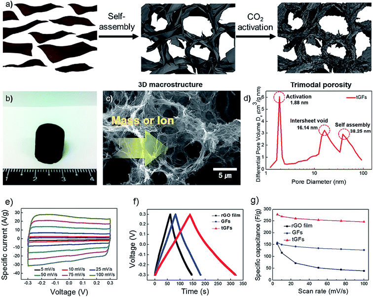 | ||
| Fig. 8 (a) Schematic illustration of preparation of the tGFs through self-assembly and CO2 activation. (b) Optical image of the resultant tGFs. (c) Concept of fast mass and ion transport through a continuous macroporous pathway. (d) Micro- and meso-porosity of the tGFs and their origin. (e) CV curves of tGF at the scan rates of 1 to 100 mV s−1. (f) Galvanostatic charge/discharge curve of tGF at 1 A g−1. (g) Rate capability of tGF at a scan rate of 5–100 mV s−1. Reproduced with permission from ref. 162, Copyright 2014 RSC. | ||
3.2. Template approach
Template assisted synthesis, which typically involves various inorganic or organic nanostructures as templates, is one of the most effective methods to prepare porous graphene materials. We broadly divide these approaches into three categories: (1) hard templating synthesis, (2) soft templating synthesis, and (3) self-generating templating synthesis.Kim and co-workers reported a straightforward self-assembly method to fabricate mechanically flexible macroporous RGO with tunable open porous morphologies (Fig. 9). Polymer-grafted GO platelets were dispersed in an organic solvent to form stable dispersion, and then cast onto a SiO2 substrate and exposed to a stream of humid air. Endothermic evaporation of the volatile organic solvent resulted in the spontaneous condensation and close packing of aqueous droplets at the organic solution surface. The pore size and the number of porous layers were effectively controlled by the concentration of the organic precursor dispersion and the length of polymer chains grafted to the GO surface. Built by this method, nitrogen doping (N-doping) RGO was also assembled and showed improved electrical properties. The specific capacitances of the as-pyrolyzed and N-doped macroporous RGO assemblies were measured to be 86.7 and 103.2 F g−1 in 1 M aqueous H2SO4 aqueous electrolyte, respectively. In contrast, the planar RGO electrode only showed 62.9 F g−1 in capacitance.170
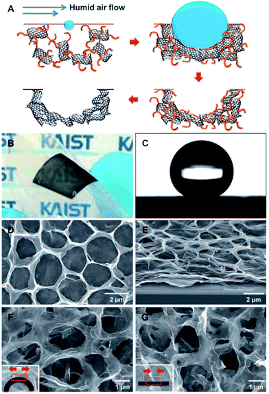 | ||
| Fig. 9 (A) Procedure for the self-assembly of RGO into macroporous carbon films. (B) A photograph of a mechanically flexible, semi-transparent macroporous RGO film on PET. (C) A water contact angle of 152° was measured for the superhydrophobic macroporous RGO film. (D) Plane-view and (E) 60°-tilted SEM images of an RGO film. (F and G) Plane-view SEM images of porous RGO film upon (F) and after (G) deformation. Reproduced with permission from ref. 170, Copyright 2010 Wiley. | ||
After that, methyl group grafted silica spheres with hydrophobic surface and uniform size are chosen as the hard template to fabricate graphene foams. By mixing the silica spheres and GOs in a neutral aqueous solution, the hydrophobic nature of both the silica templates and GOs central planes induces self-assembled lamellar-like structures. The as-made composites are transformed into graphene after calcination under inert atmosphere. This nanoporous graphene foam has a high surface area of 851 m2 g−1 and an ultra-large pore volume of ∼4.28 cm3 g−1.164 A three-dimensional bubble graphene film possessed controllable and uniform macropores and adjustable microstructure was achieved by using polymethyl methacrylate latex spheres as a hard template. This macroporous graphene film had BET specific surface area of 128 m2 g−1 and exhibited good electrochemical capacitance at a high scan rate of 1.0 V s−1. The capacitance of macroporous bubble graphene film and compact graphene film electrodes were determined to be 92.7 and 30.6 F g−1, respectively.171
The inorganic nanoparticles without surface decoration are also used as hard templates. A RGO sample possessing a hierarchical pore structure was prepared using commercially available low-cost hydrophobic CaCO3 spheres with different particle sizes. This porous graphene with an average diameter of about 50 nm had a specific surface area of 540 m2 g−1 and exhibited a gravimetric charge–discharge capacitance of 201 F g−1 at a current density of 0.1 A g−1. After 1000 cycles, the electrode retained about 98.4% of its initial capacitance.172 Since the above-mentioned hard templates have large particle size, the obtained graphene composed of abundant numbers of large pore and macropores. By incorporating MnO2 nanoparticles into graphene and then selectively removing the nanoparticles, porous graphene with a high surface area of 1374 m2 g−1 and a mesoporous structure (∼2.4 nm) was obtained. These mesoporous graphene could effectively promote contact with the electrolytes and electrode material, and shorten the diffusion pathway of ions through the porous sheets, resulting in an improved specific capacitance of 154 F g−1 at 500 m V s−1 and a low capacitance loss of 12% after 5000 cycles.173
Freeze drying, a wet shaping technique for porous materials, has been explored to produce graphene composite aerogels.168 Directly put aqueous homogeneous mixtures containing polystyrene sulfonate-stabilized RGO sheets and PVA (or GO sheets and PVA) into liquid nitrogen, followed by freeze-drying of the frozen samples produced graphene composite aerogels with well-ordered microstructures. In a series of follow-up studies, a variety of modified freeze drying methods for graphene aerogels have been reported.174–177 Some graphene and graphene composites like graphene–CNT aerogel are also exploited as supercapacitor electrode material.
3D N-doped graphene–CNT networks can be obtained by hydrothermal treatment, freeze-drying and subsequent carbonization of graphene oxide-dispersed pristine CNTs in the presence of pyrrole. The resulting samples used as supercapacitor electrodes show specific capacitance of 180 F g−1 at a current density of 0.5 A g−1, and retain 96% of the initial capacitance after 3000 cycles.178 When 3-D macroporous nickel foam substrate was used, graphene aerogel–nickel foam hybrid material prepared through freeze-drying and the subsequent thermal annealing of the precursors showed improved electrochemical performance. The resulted graphene aerogels possessed hierarchical porosity and high conductivity. When it was used as binder-free electrode in supercapacitors, a high rate capability, good electrochemical cyclic stability, and a high specific capacitance of 366 F g−1 at a current density of 2 A g−1 were achieved.179
Macroporous graphene films can be prepared by simply electrophoretic depositing (EPD) GO or RGO onto 3-D macropore nickel foam. EPD offers remarkable advantages over other methods for the synthesis of porous graphene films. It does not require expensive instrumentation, high temperatures, or low-vacuum pressures. This method is also not time-consuming, since materials grown in this fashion have a high growth rate.180,181
Graphene nanosheets are deposited on nickel foams with 3D porous structure by an EPD method using the colloids of graphene monolayers in ethanol. A high specific capacitance of 164 F g−1 is obtained from cyclic voltammetry measurement at a scan rate of 10 mV s−1. When the current densities are set as 3 and 6 A g−1, the specific capacitance values still reach to 139 and 100 F g−1, respectively. The high capacitance is attributed to nitrogen atoms in oxidized product of p-phenylene diamine adsorbed on the surface of the graphene nanosheets.182 EPD approach had also been developed for the fabrication of RGO composites based on GO suspension and nickel ions decorated GO colloidal suspension. The zeta-potential of GO aqueous solution is negative, which makes anode deposition feasible, and have positive value when GO is positively charged by adsorption of nickel ion, accordingly cathode deposition. Direct assembly by EPD in water medium facilitated the transformation from GO to RGO and resulted in 3D porous or flowerlike RGO hybrid films on different substrates. By adjusting the concentration of the precursor, the EPD voltage and time, and the pH value of the solution, the morphologies, the film thickness and the pore structure could be tailored. Moreover, the electrochemical capacitive behavior was improved for both RGO and its composites after EPD process.183
Although GO and RGO are good candidates to synthesize the meso/macro-porous graphene based on solution process, the resulted samples usually showed low electrical conductivity because long-order sp2 carbon was only partially reestablished. Hence, some templating methods based on directly grown graphene were reported. CVD, an excellent method to grow graphene film with controlled layers and high electrical conductivity, was reported to synthesize graphene foams with a graphene 3D network monolith. These graphene foams showed extraordinary electrical and mechanical properties.166 The growth mechanism of graphene film on nickel foam is analogous to that on nickel substrate.184
Similar to other dielectrics like ZnS, SiO2, Al2O3, Si3N4, Rh-YSZ (yttria-stabilized-zirconia)–Si(111) surface, which had already been used as substrate to grow graphene,185–189 MgO particle was found to be a good template to form graphene using CVD method based on catalytic decomposition of the carbon source precursor and adsorbing carbon atom. A template CVD approach was explored to produce nanomesh graphene with a well-controlled structure on the gram scale. MgO layers with meshes were firstly prepared by a boiling treatment to construct Mg(OH)2 layers and followed by calcination at high temperature to remove water (Fig. 10). After the introduction of methane to CVD growth of graphene, one or two graphene layers were formed on the MgO surface along (200) MgO lattice planes. Graphene had one or two graphene layers and specific surface areas of up to 1654 m2 g−1. Its unique porous structure brought excellent electrochemical capacitance up to 255 F g−1.165 When methane was changed into ferrocene as the carbon precursor and porous MgO as sacrificial template, the obtained graphene layers showed a specific surface area up to 1754 m2 g−1 and a highly porous structure with small mesopores of 4–8 nm, large mesopores of 10–20 nm and additional macropores. As a result, a specific capacitance of 303 F g−1 (areal capacitance up to 17.3 mF cm−2) and a nearly tenfold shorter time constant were achieved when compared with those of nonporous and stacked graphene electrodes.190
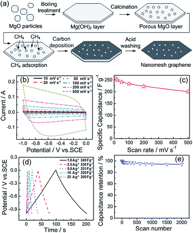 | ||
| Fig. 10 (a) Illustration of the formation of the polygonal nanomesh graphene; (b–e) electrochemical properties of the nanomesh graphene electrode. (b) CV curves from 10 to 500 mV s−1; (c) specific capacitance vs. scan rate; (d) galvanostatic charge/discharge curves at different constant currents. Specific capacitance values were calculated from the discharge curve for each current; (e) cycling performance (200 mV s−1).165 Reproduced with permission from ref. 165, Copyright 2011 RSC. | ||
By changing MgO platelets with MgCO3·3H2O fibers, one-dimensional highly electroconductive mesoporous graphene nanofibers (GNFs) were obtained by a CVD method. GNFs exhibited good structural stability, high surface area, mesopores in a large amount, and high electrical conductivity (three times that of carbon nanotube aggregates). It was used as an electrode in a 4 V supercapacitor, and exhibited high energy density in a wide range of high power density and excellent cycling stability. The short diffusion distance for ions of ionic liquids electrolyte to the surface of GNFs yielded high surface utilization efficiency and a capacitance up to 15 μF cm−2, higher than that of single-walled carbon nanotubes.191,192 Besides CVD methods, direct carbonization of carbon source precursor was also realizable. For example, 3D pillared-porous carbon nanosheets with supporting carbon pillars in the adjacent carbon layers had been prepared using MgO hard template. The unique structure endows the high-rate transportation of electrolyte ions and electrons throughout the electrode matrix, resulting in an excellent electrochemical performance.192
The layered structural materials whose interlayer spacing is comparable to one-to-two graphene thickness are also used as hard templates to synthesize porous graphene. Scalable single graphene sheets could be synthesized when zeolite Ni-MCM-22 was used as both catalyst and template. Ni-MCM-22 was produced from MCM-22 (IZA code: MWW) which has typical layer spacing similar with the thickness of one or two layered graphene. As a confined space, the interlayers of MCM-22 can be filled with sucrose and nickel ions by dipping. The obtained graphene has a specific surface area of 784 m2 g−1, relatively high conductivity of 73.6 S m−1, and controllable two-dimensional sizes. Its reveals excellent electrochemical double layer capacitance and galvanostatic charge/discharge properties with specific capacitances of 233 F g−1 in aqueous KOH.193 Three-dimensional sponge-like graphene nanoarchitectures was prepared using a cobalt phthalocyanine molecules as a hard template. The morphology of graphene was shaped by acid-functionalized multiwalled carbon nanotubes. The sequential “bottom-up” molecular synthesis and subsequent carbonization process were fast to complete. The 3D nanoarchitectures are able to deliver an energy density of 7.1 W h kg−1 even at an extra high power density of 48![[thin space (1/6-em)]](https://www.rsc.org/images/entities/char_2009.gif) 000 W kg−1. Moreover, the electrode exhibited high cyclic stability (>90% after 10
000 W kg−1. Moreover, the electrode exhibited high cyclic stability (>90% after 10![[thin space (1/6-em)]](https://www.rsc.org/images/entities/char_2009.gif) 000 cycles) in ionic liquids and 1 M H2SO4, respectively.194
000 cycles) in ionic liquids and 1 M H2SO4, respectively.194
A solution deposition method via a controlled low-concentration monomicelle close-packing assembly approach was reported to synthesize two-dimensional ordered mesoporous carbon nanosheets (Fig. 11). These obtained carbon nanosheets possess only one layer of ordered mesopores on the surface of a substrate, typically the inner walls of anodic aluminum oxide pore channels, and can be further converted into mesoporous graphene nanosheets by carbonization. The atomically flat graphene layers with mesopores provide high surface area while the ordered mesopores perpendicular to the graphene layer facilitates ion transport as well as volume expansion flexibility.195
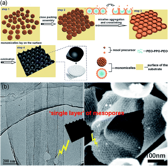 | ||
| Fig. 11 (a) Schematic of the formation process for the ordered mesoporous graphene nanosheets; (b) TEM image of the mesoporous graphene nanosheets synthesized from the low-concentration close-packing assembly of monomicelles; (c) SEM images of the mesoporous graphene nanosheets. Reproduced with permission from ref. 195, Copyright 2013 ACS. | ||
A three-dimensional graphene-based hierarchically porous carbon (3DGHPC) was prepared by a dual-template strategy following a coating–solvent evaporation–thermal polymerization–carbonation–etching template step. The coated polymers on SiO2 spheres were converted to carbon phase, and the GO was efficiently reduced to graphene simultaneously. The 3DGHPC exhibits a higher specific surface area of 384.4 m2 g−1 and an improved pore volume of 0.73 cm3 g−1.196 Interestingly, using an anti-solvent hexane to stabilize the GO suspension, Lee and co-workers reported a non-stacked reduced graphene oxide (NS-rGO) with a high surface area (1435.4 m2 g−1) and a ultrahigh pore volume (4.11 cm3 g−1). Hexane is a non-polar aprotic molecule and does not have any interaction with various oxygen groups of GO, but it can provide a hydrogen bonding interaction of oxygen functional groups within GO, which hinders the re-stacking of the GO sheets. It is crucial that electrode materials have both a high surface area and high pore volume at the same time to develop supercapacitors with a high capacitance and rate capability. A specific capacitance of 236.8 F g−1 was obtained for NS-rGO electrode at a current density of 1 A g−1 in 6 M KOH electrolyte.197
A novel soft template method is developed to synthesize a mesoporous carbon/graphene (MCG) composite. The specific capacitance of MCG composite is up to 242 F g−1 at the current density of 0.5 A g−1, which is much higher than mesoporous carbon, graphene and a sample made by mechanical mixing of mesoporous carbon with graphene. When the current density is increased to 1, 2 and then to 4 A g−1, the specific capacitances of the sample decrease to 203, 168 and 154 F g−1, respectively. Such a decrease is attributed to the insufficient time available for ion diffusion and adsorption inside the smallest pores within the large particles.198 Without addition of surfactant, hollow graphene oxide spheres (HGOSs) were fabricated from graphene oxide nanosheets (GONs) utilizing a water-in-oil (W/O) emulsion technique. The oxidation time for preparing GONs is a crucial factor for the formation and morphology of HGOSs. With increasing oxidation time, the morphology and surface topography of HGOSs vary from irregular and rough to uniform and smooth shape with decreasing diameter. The hollow structure, thin and porous shells consisting of graphene also exhibited improved electrochemical performance.199
Recently, Ma and co-workers developed a facile, rapid and environmentally friendly process, called “burn-quench method”, which allows for controllable synthesis of mesoporous nanographene with large quantity, lower than 5 layers, high surface area and electric conductivity (Fig. 12).200 This alternative way is ignition of magnesium ribbons in carbon dioxide gas, followed by in situ quenching technique. Apart from being eco-friendly, the process has several advantages such as high-yield, low-cost, and time-saving. 1 g of nanographene can be obtained from approximately 25 g of Mg ribbons by the burn-quench method shown in Fig. 12a. The resulting Mg ions in the solution after dissolving Mg and MgO can be re-converted into Mg materials for recycled usage of further nanographene preparation. So this burn-quench method has potential for the scale-up synthesis of graphene materials. Electrochemical electrodes composed of nanographene mesoporous architecture both for supercapacitors and lithium ion batteries yield high specific capacitance, rate capability, energy density and cyclic stability.
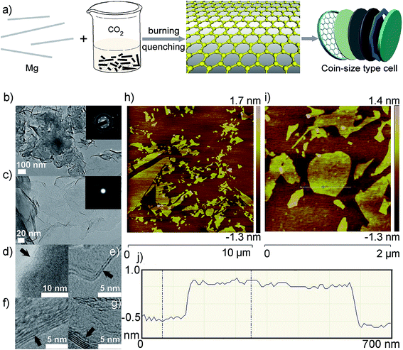 | ||
| Fig. 12 (a) Scheme of the burn-quench method and assembly of the electrochemical cells; (b–j) TEM and AFM images of nanographene sheets. (b and c) low-magnification TEM images, (c) enlargement of (b). Insets in (b) and (c) are the corresponding SAED patterns; (d–g) HRTEM images of the controlled layers of graphene with monolayers, double layers, four layers, and five layers, respectively; (h) AFM image of the nanographene sheets on a mica substrate; (i) enlargement of the AFM image in (h); (j) height of the nanographene sheets marked in (i). Reproduced with permission from ref. 200, Copyright 2013 Wiley. | ||
With further controlling the reaction of CO2 with Mg metal at desired temperature and atmosphere, shape-controlled synthesis of several different types of nanocarbons including mesoporous graphene, carbon nanotubes, and hollow carbon nanoboxes was achieved (Fig. 13). The hollow carbon nanoboxes were firstly reported by this method. The method described here allows effective control of the shape and dimension of nanocarbons through manipulation of reaction temperature. The formation mechanisms of nanocarbons were discussed by analysis of their morphology and preferred orientations in combination with different phase interface reaction and self-generated template-guided growth mechanism. The as-synthesized nanocarbons were used as electrodes for symmetrical supercapacitor, which exhibits high capacitance, good cycling stability, and high energy density value of 80 W h kg−1.201 The studies of supercapacitors based on porous graphene obtained by template methods are summarized in Table 2, where the synthetic method and the capacitance values are given.
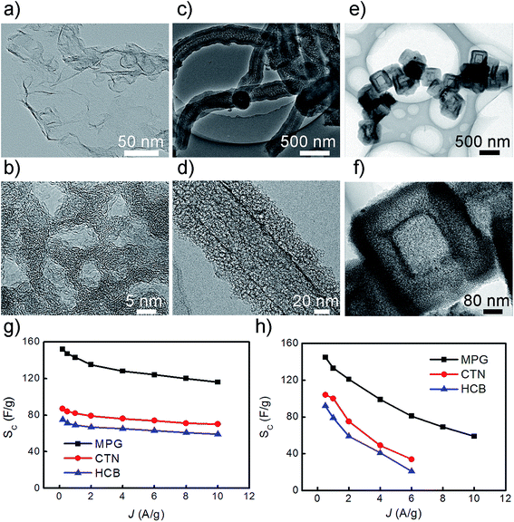 | ||
| Fig. 13 TEM images of nanocarbons synthesized at different temperatures, (a) sheet-like morphology of MPG in which scrolls and corrugations present; (b) high-resolution image of 5–10 nm diameter mesopore in the MPG; (c–d) low- and medium-magnification images of carbon tubular nanostructures; (e) low magnification image of HCB shows uniform particle size, hollow core microstructure and cubic shape; (f) medium-magnification image of HCB shows that the shell thickness and the side length of HCB are approximately as large as 80–100 and 230 ± 30 nm; (g–h) the specific capacitance of nanocarbon electrodes in 6 M KOH aqueous and EMIMBF4 electrolytes, respectively. Reproduced with permission from ref. 201, Copyright 2013 NPG. | ||
| Materials | Synthetic method | SSA (m2 g−1) | Conductivity (S m−1) | Electrolyte | CSa (F g−1) | Ref. |
|---|---|---|---|---|---|---|
| a The maximum value.b Values of capacitance for the three-electrode cell system. | ||||||
| N-Doped RGO films | Self-assembly of GO platelets | — | 64![[thin space (1/6-em)]](https://www.rsc.org/images/entities/char_2009.gif) 900 900 |
1 M H2SO4 | 103.2b | 170 |
| Nanomesh graphene | CVD using MgO nanomesh as template | 1654 | — | 6 M KOH | 255b | 165 |
| Macroporous bubble graphene film | PMMA latex spheres as hard template | 128 | — | 1 M H2SO4 | 93b | 171 |
| Hierarchical porous RGO | CaCO3 nanospheres as hard template | 540 | 5 | 1 M H2SO4 | 201 | 172 |
| N-Doped graphene/CNT networks | Hydrothermal treatment, freeze drying and carbonization of pyrrole | — | — | 6 M KOH | 180b | 178 |
| Graphene aerogels | Freeze drying to form GO aerogels followed by thermal reduction | 463 | 71 | 6 M KOH | 366b | 179 |
| Porous graphene | Etching graphene of graphene sheets by MnO2 nanoparticles | 1374 | — | 25% KOH | 241b | 173 |
| Mesoporous carbon/graphene composite | Triblock copolymer Pluronic F12 as soft template | 546 | — | 6 M KOH | 242b | 198 |
| Functionalized graphene sheets | Thermal annealing of GO attached on Mg(OH)2 nanosheet | 285 | 3 | 5 M KOH | 456b | 202 |
| Anti-solvent derived non-stacked RGO | Thermal reduction of hexane stabilized GO | 1435 | 3000 | 6 M KOH | 236.8 | 197 |
| Graphene sheets with nanopores | CVD using MgO as template and ferrocene as carbon source | 1754 | 188 | 6 M KOH | 303 | 190 |
| Sponge-like graphene | Microwave synthesis and carbonation of CoPc using AF-MWCNT as supports followed by exfoliation of graphite | 418 | — | 1 M H2SO4 | 68b | 194 |
| Graphene films on nickel foam substrate | EPD of RGO | — | — | 6 M KOH | 164b | 182 |
| Mesoporous graphene nanofibers | CVD using MgCO3·3H2O as template | 1280 | — | EMIM BF4 | 193 | 191 |
| Porous graphene | Zeolite Ni-MCM-22 as a catalyst and template | 794 | — | 6 M KOH | 233 | 193 |
| 3-D graphene-based frameworks | Hard templating method and freeze drying | 295 | — | 1 M H2SO4 | 226b | 140 |
| Ordered mesoporous nanographene | Burn-quench method | 756 | 150 | EMIM BF4 | 95 | 200 |
| Mesoporous graphene | Controlled reaction of Mg with CO2 | 762 | — | EMIM BF4 | 145 | 201 |
3.3. Self-assembly of graphene nanosheets
Self-assembly of two-dimensional graphene nanosheets is an important strategy to produce 3D macroscopic graphene architectures.203–206 The pore sizes of such structures are in the range from sub-micrometer to several micrometers, which bring about ultralight, high mechanical strength, compressibility, and excellent conductivity properties. The macroporous structure not only prevents individual graphene nanosheets from aggregating and restacking during the process of assembling, but also ensures a sufficient contact area between the electrolyte and electrode.207 Moreover, 3D porous frameworks provide fast ion diffusion channels while the framework itself acts as a continuous conductive network ensuring fast electron transfer, resulting in excellent rate capability.Shi and co-workers reported a self-assembled graphene hydrogel (SGH) via a convenient one-step hydrothermal method at 180 °C for 12 h.208 The SGH has a well-defined and interconnected 3D porous network, and the framework of SGH is formed by the partial overlapping or coalescing of flexible graphene nanosheets with physical cross-linking sites (Fig. 14a–e). It is believed that the formation of the SGH was driven by the residual hydrophilic oxygenated groups of reduced GO sheets and the π–π stacking interactions of graphene sheets. In addition to the excellent mechanical strength, the SGH is electrically conductive with a conductivity of about 5 × 10⁻³ S cm−1 (Fig. 14f). The SGH can be cut into slices with a knife, and they were used as the electrodes to assemble symmetric supercapacitors without using a binding agent and conducting additive because of its excellent mechanical strength, high porosity and conductivity (Fig. 14g). The specific capacitances of 175 and 152 F g−1 for the SGH were obtained at potential scan rates of 10 and 20 mV s−1 in 5 M KOH aqueous electrolyte, respectively (Fig. 14h).
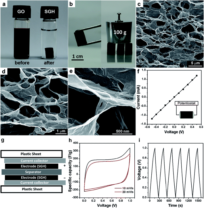 | ||
| Fig. 14 (a) Photographs of a 2 mg mL−1 homogeneous GO aqueous dispersion before and after hydrothermal reduction at 180 °C for 12 h; (b) photographs of a strong SGH allowing easy handling and supporting weight; (c–e) SEM images with different magnifications of the SGH; (f) room temperature I–V curve of the SGH exhibiting Ohmic characteristic, inset shows the two-probe method for the conductivity measurements; (g) schematic of SGH-based supercapacitor device; (h) CVs of the SGH-based supercapacitor at two different scan rates; (c) galvanostatic charge/discharge curves of the SGH-based supercapacitor at a constant current of 1 A g−1. Reproduced with permission from ref. 208, Copyright 2010 ACS. | ||
Subsequently, in order to obtain higher conductivity of graphene hydrogel (GH), Shi and co-workers further used hydrazine (Hz) or hydroiodic acid (HI) for reduction of the GH.209 The chemical reduction of GH was carried out by immersing it into an aqueous solution of HI (55%) or hydrazine monohydrate (50%) in a sealed cuvette. The reduction was conducted for 3 or 8 h at 100 °C for HI and 95 °C for Hz, respectively. The chemically reduced GHs possess high conductivities of 1.3–3.2 S m−1 and SSAs in the range from 780 to 950 m2 g−1. Moreover, the further treatment of GH with reducing agent has less impact on the microscopic pore structure of GH (Fig. 15a–d). The supercapacitor based on the Hz-reduced GH exhibited a high specific capacitance of 220 F g−1 at 1 A g−1 in 5 M KOH aqueous electrolyte, and this capacitance can be maintained for 74% as the discharging current density was increased up to 100 A g−1 (Fig. 15g and h). Furthermore, the capacitor exhibited a high power density of 30 kW kg−1 and energy density of 5.7 W h kg−1 at 100 A g−1. This is possibly attributed to the improved conductivity of reduced hydrogels accelerating its charge-transfer during the discharge processes at high current densities.
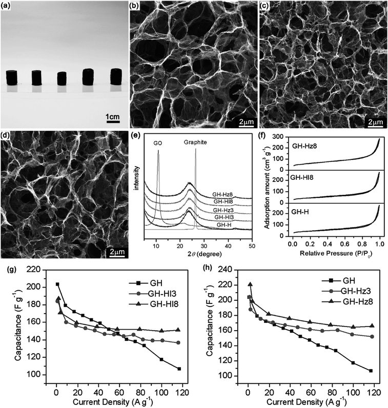 | ||
| Fig. 15 (a) Photographs of GH, GH-HI3, GH-HI8, GH-Hz3, and GH-Hz8 (from left to right); (b–d) SEM images of the interior microstructures of freeze-dried GH (b), GH-HI8 (c), and GH-Hz8 (d), respectively; (e) XRD patterns of graphite, GO, and GHs; (f) N2 adsorption–desorption isotherms of freeze-dried GH, GH-HI8, and GH-Hz8; plots of specific capacitance versus discharging current density for GH-HI (g) and GH-Hz (h) compared with GH. Reproduced with permission from ref. 209, Copyright 2011 ACS. | ||
Since their pioneering work, hydrothermal or solvothermal reaction had been widely applied to fabricate 3D macroscopic graphene architecture via self-assembly of graphene nanosheets.207,210 Yu and co-workers reported the hydrothermal synthesis of macroscopic nitrogen-doped graphene hydrogels (GN-GH) by using organic amine and graphene oxide as precursors.211 The organic amine is not only acting as nitrogen sources to prepare the nitrogen-doped graphene, but also as an important structural modifier to control the assembly of graphene sheets in the 3D structures (Fig. 16a–d). The obtained nitrogen-doped graphene hydrogel exhibited remarkably enhanced ultrafast supercapacitor performance. Even at an ultrafast charge/discharge current density of 185 A g−1, a specific capacitance of 113.8 F g−1 and a high power density of 205.0 kW kg−1 could be obtained in 5 M KOH electrolyte (Fig. 16e and f). The studies of 3D macroscopic graphene architecture based supercapacitors are summarized in Table 3, where the synthetic method and the capacitance values are given.
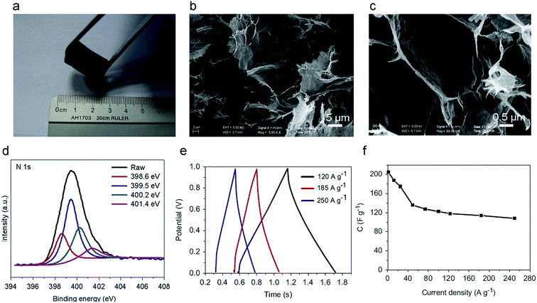 | ||
| Fig. 16 (a) Photographs of a typical GN-GH using GO and ethylenediamine (100 μL) as precursors after hydrothermal process at 180 °C for 12 h; (b) SEM image of the typical GN-GH microstructures; (c) magnified SEM image of the typical GN-GH microstructures; (d) the high-resolution XPS spectra of the N 1s region; (e) galvanostatic charge/discharge curves of the GN-GH supercapacitor under different constant current densities; (f) plots of specific capacitance versus discharging current density. Reproduced with permission from ref. 211, Copyright 2013 Elsevier. | ||
| Synthetic method | SSA (m2 g−1) | Conductivity (S m−1) | Electrolyte | CSa (F g−1) | Pa (kW kg−1) | Ref. |
|---|---|---|---|---|---|---|
| a The maximum value.b Values of capacitance for the three-electrode cell system. | ||||||
| Hydrothermal treatment of GO aqueous dispersion | — | 0.5 | 5 M KOH | 175 | — | 208 |
| Graphene hydrogels further reduced with hydrazine | 951 | 3.2 | 5 M KOH | 222 | 30 | 209 |
| Hydrothermal treatment of organic amine and GO | — | — | 5 M KOH | 190.1 | 245.0 | 211 |
| Crosslinking reaction with ethylene diamine followed by hydrazine reduction | 745 | 1351 | 2 M KOH | 232 | — | 212 |
| Hydrothermal treatment of urea and GO | 1521 | 600 | 6 M KOH | 326b | — | 213 |
| Solvothermal treatment of hydroxylamine and GO | — | — | 25% KOH | 205 | 20.5 | 214 |
| Hydrothermal treatment of ascorbic acid and GO | — | — | H2SO4–PVA gel | 196 | 5 | 215 |
| Chemical reaction of L-glutathione and GO | 315.2 | 2 | 0.5 M Na2SO4 | 157.7 | 5 | 216 |
| Chemical reaction of sodium ascorbate and GO | — | 1 | 1 M H2SO4 | 240b | — | 217 |
| Chemical reaction of pyrrole monomers and GO | — | — | 1 M H2SO4 | 498b | — | 218 |
| Hydrothermal treatment of pyrrole monomers and GO | 463 | — | 3 M NaClO4 | 350b | — | 219 |
| Hydrothermal treatment of HCl and GO | 322 | — | 6 M KOH | 220 | — | 220 |
| Hydrothermal treatment of GO and glucose | — | — | 5 M KOH | 140 | — | 221 |
| Solvothermal treatment of GO and activated carbon | 1266 | — | 1 M TEA BF4/PC | 116.5 | 7 | 222 |
| Graphene hydrogels deposited in nickel foams reduced by vitamin C | 1725 | — | 5 M KOH | 45.6 mF cm−2 | — | 223 |
| Electrochemically reduced GO | — | — | 1 M Na2SO4 | 131.6a | — | 224 |
4. Conclusions and perspectives
Owing to their high surface area, remarkable thermal conductivity, excellent electronic conductivity and mechanical properties, porous graphene materials have aroused great academic interests. Porous structures are favorable for fast ion/electron transport, and facilitate sufficient contact between electrolyte and graphene materials. In broad terms, low-cost, and time-saving methods for future production of porous graphene with controllable nanostructures are still desired. Besides, the pore structures and morphologies of porous graphene materials highly depend on the processing conditions, which make the precise tailoring for surface area, interconnected porosity, and pore size distribution an imminent technological challenge. Therefore, further application of porous graphene materials still requires the proper realization of their distinct structure.Although high specific surface area enhances mass transfer during electrochemical reactions, the conductivity of electrode materials may be negatively affected due to loosing contact among graphene sheets. This greatly destroys the prospect for porous graphene in practical applications. To solve the paradox between high specific surface area and excellent conductivity, the promising strategies include hetero-atom doping, chemical-bonding, perfect lattices and removal of oxygen atoms. Besides, theoretical research should also be promoted systematically to reveal the relationship between porosity and electrical properties.
Graphene-based composites are promising candidates as future high-performance supercapacitor electrode materials because the synergetic effects can provide full scope to the potentiality of each component. Combination of conducting polymers or metal oxides/hydroxides with graphene offers a pathway for material selection and optimization. Faradaic materials are well-known for their high capacitance and highly reversible redox reactions, while graphene is an ideal matrix for composites due to the chemical stability and sophisticated porosity.
In conclusion, porous graphene, as an attractive electrode material, has inspired both academic and industrial interests. The graphene paradigm determines the novel pathways for the fabrication of high-performance electrode materials for supercapacitors. There is no doubt that the extensive investigation of porous graphene should surely open a colourful vista for next-generation energy storage devices in future.
Acknowledgements
This work was supported by the Knowledge Innovation Program of the Chinese Academy of Sciences (no. KJCX2-YW-W26), Beijing Municipal Science and Technology Commission (no. Z111100056011007), and the National Natural Science Foundation of China (no. 51403211, 51472238, and 51025726).References
- F. Béguin, V. Presser, A. Balducci and E. Frackowiak, Adv. Mater., 2014, 26, 2219 CrossRef PubMed.
- M. Conte, Fuel Cells, 2010, 10, 806 CrossRef CAS.
- P. Simon and Y. Gogotsi, Nat. Mater., 2008, 7, 845 CrossRef CAS PubMed.
- P. Jampani, A. Manivannan and P. N. Kumta, Electrochem. Soc. Interface, 2010, 19, 57 CAS.
- J. R. Miller and P. Simon, Science, 2008, 321, 651 CrossRef CAS PubMed.
- A. Burke, Int. J. Energy Res., 2010, 34, 133 CrossRef CAS.
- G. Yu, X. Xie, L. Pan, Z. Bao and Y. Cui, Nano Energy, 2013, 2, 213 CrossRef CAS PubMed.
- P. J. Hall, M. Mirzaeian, S. I. Fletcher, F. B. Sillars, A. J. R. Rennie, G. O. Shitta-Bey, G. Wilson, A. Cruden and R. Carter, Energy Environ. Sci., 2010, 3, 1238 CAS.
- M. Winter and R. J. Brodd, Chem. Rev., 2004, 104, 4245 CrossRef CAS.
- L. L. Zhang and X. S. Zhao, Chem. Soc. Rev., 2009, 38, 2520 RSC.
- A. S. Arico, P. Bruce, B. Scrosati, J. M. Tarascon and W. Van Schalkwijk, Nat. Mater., 2005, 4, 366 CrossRef CAS PubMed.
- D. R. Rolison, R. W. Long, J. C. Lytle, A. E. Fischer, C. P. Rhodes, T. M. McEvoy, M. E. Bourga and A. M. Lubers, Chem. Soc. Rev., 2009, 38, 226 RSC.
- J. R. Miller and A. F. Burke, Electrochem. Soc. Interface, 2008, 17, 53 CAS.
- L. L. Zhang, Y. Gu and X. S. Zhao, J. Mater. Chem. A, 2013, 1, 9395 CAS.
- A. K. Geim and K. S. Novoselov, Nat. Mater., 2007, 6, 183 CrossRef CAS PubMed.
- A. K. Geim, Science, 2009, 324, 1530 CrossRef CAS PubMed.
- K. S. Novoselov, V. I. Fal'ko, L. Colombo, P. R. Gellert, M. G. Schwab and K. Kim, Nature, 2012, 490, 192 CrossRef CAS PubMed.
- Y. Y. Wen, C. C. Huang, L. Z. Wang and D. Hulicova-Jurcakova, Chin. Sci. Bull., 2014, 59, 2102 CrossRef CAS.
- A. K. Geim, Angew. Chem., Int. Ed., 2011, 50, 6966 CrossRef CAS PubMed.
- K. S. Novoselov, A. K. Geim, S. V. Morozov, D. Jiang, Y. Zhang, S. V. Dubonos, I. V. Grigorieva and A. A. Firsov, Science, 2004, 306, 666 CrossRef CAS PubMed.
- C. Berger, Z. M. Song, T. B. Li, X. B. Li, A. Y. Ogbazghi, R. Feng, Z. T. Dai, A. N. Marchenkov, E. H. Conrad, P. N. First and W. A. de Heer, J. Phys. Chem. B, 2004, 108, 19912 CrossRef CAS.
- R. S. Edwards and K. S. Coleman, Acc. Chem. Res., 2013, 46, 23 CrossRef CAS PubMed.
- B. Wu, D. C. Geng, Y. L. Guo, L. P. Huang, Y. Z. Xue, J. Zheng, J. Y. Chen, G. Yu, Y. Q. Liu, L. Jiang and W. P. Hu, Adv. Mater., 2011, 23, 3522 CrossRef CAS PubMed.
- Y. Z. Xue, B. Wu, L. Jiang, Y. L. Guo, L. P. Huang, J. Y. Chen, J. H. Tan, D. C. Geng, B. R. Luo, W. P. Hu, G. Yu and Y. Q. Liu, J. Am. Chem. Soc., 2012, 134, 11060 CrossRef CAS PubMed.
- X. S. Li, W. W. Cai, J. An, S. Kim, J. Nah, D. X. Yang, R. Piner, A. Velamakanni, I. Jung, E. Tutuc, S. K. Banerjee, L. Colombo and R. S. Ruoff, Science, 2009, 324, 1312 CrossRef CAS PubMed.
- X. Cui, C. Z. Zhang, R. Hao and Y. L. Hou, Nanoscale, 2011, 3, 2118 RSC.
- V. Nicolosi, M. Chhowalla, M. G. Kanatzidis, M. S. Strano and J. N. Coleman, Science, 2013, 340, 1420 CrossRef CAS.
- S. F. Pei and H. M. Cheng, Carbon, 2012, 50, 3210 CrossRef CAS PubMed.
- S. Park and R. S. Ruoff, Nat. Nanotechnol., 2009, 4, 217 CrossRef CAS PubMed.
- Y. Chen, X. Zhang, P. Yu and Y. W. Ma, Chem. Commun., 2009, 4527 RSC.
- J. T. Zhang and C. M. Li, Chem. Soc. Rev., 2012, 41, 7016 RSC.
- D. Zhang, X. Zhang, Y. Chen, C. Wang and Y. Ma, Electrochim. Acta, 2012, 69, 364 CrossRef CAS PubMed.
- Q. Q. Kong, C. M. Chen, Q. Zhang, X. H. Zhang, M. Z. Wang and R. Cai, J. Phys. Chem. C, 2013, 117, 15496 CAS.
- C. Zhang, W. Lv, X. Y. Xie, D. M. Tang, C. Liu and Q. H. Yang, Carbon, 2013, 62, 11 CrossRef CAS PubMed.
- Y. Z. Liu, C. M. Chen, Y. F. Li, X. M. Li, Q. Q. Kong and M. Z. Wang, J. Mater. Chem. A, 2014, 2, 5730 CAS.
- J. L. Liu, H. P. Yang, S. G. Zhen, C. K. Poh, A. Chaurasia, J. S. Luo, X. Y. Wu, E. K. L. Yeow, N. G. Sahoo, J. Y. Lin and Z. X. Shen, RSC Adv., 2013, 3, 11745 RSC.
- M.-Q. Zhao, Q. Zhang, J.-Q. Huang and F. Wei, Adv. Funct. Mater., 2012, 22, 675 CrossRef CAS.
- Y. Harima, S. Setodoi, I. Imae, K. Komaguchi, Y. Ooyama, J. Ohshita, H. Mizota and J. Yano, Electrochim. Acta, 2011, 56, 5363 CrossRef CAS PubMed.
- I. Y. Jeon, S. Zhang, L. P. Zhang, H. J. Choi, J. M. Seo, Z. H. Xia, L. M. Dai and J. B. Baek, Adv. Mater., 2013, 25, 6138 CrossRef CAS PubMed.
- V. Leon, M. Quintana, M. A. Herrero, J. L. G. Fierro, A. de la Hoz, M. Prato and E. Vazquez, Chem. Commun., 2011, 47, 10936 RSC.
- I. Y. Jeon, Y. R. Shin, G. J. Sohn, H. J. Choi, S. Y. Bae, J. Mahmood, S. M. Jung, J. M. Seo, M. J. Kim, D. W. Chang, L. M. Dai and J. B. Baek, Proc. Natl. Acad. Sci. U. S. A., 2012, 109, 5588 CrossRef CAS PubMed.
- D. Zhang, X. Zhang, X. Sun, H. Zhang, C. Wang and Y. Ma, Electrochim. Acta, 2013, 109, 874 CrossRef CAS PubMed.
- M. D. Stoller, S. Park, Y. Zhu, J. An and R. S. Ruoff, Nano Lett., 2008, 8, 3498 CrossRef CAS PubMed.
- G. P. Wang, L. Zhang and J. J. Zhang, Chem. Soc. Rev., 2012, 41, 797 RSC.
- Y. Gao, Y. S. Zhou, M. Qian, H. M. Li, J. Redepenning, L. S. Fan, X. N. He, W. Xiong, X. Huang, M. Majhouri-Samani, L. Jiang and Y. F. Lu, RSC Adv., 2013, 3, 20613 RSC.
- Y. Wang and Y. Xia, Adv. Mater., 2013, 25, 5336 CrossRef CAS PubMed.
- J. Yan, Q. Wang, T. Wei and Z. Fan, Adv. Energy Mater., 2014, 4, 1300816 Search PubMed.
- S. Shi, C. J. Xu, C. Yang, J. Li, H. D. Du, B. H. Li and F. Y. Kang, Particuology, 2013, 11, 371 CrossRef PubMed.
- A. K. Shukla, A. Banerjee, M. K. Ravikumar and A. Jalajakshi, Electrochim. Acta, 2012, 84, 165 CrossRef PubMed.
- H. Ji, X. Zhao, Z. Qiao, J. Jung, Y. Zhu, Y. Lu, L. L. Zhang, A. H. MacDonald and R. S. Ruoff, Nat. Commun., 2014, 5, 3317 Search PubMed.
- T. Chen and L. M. Dai, Mater. Today., 2013, 16, 272 CrossRef CAS PubMed.
- G. A. Snook, P. Kao and A. S. Best, J. Power Sources, 2011, 196, 1 CrossRef CAS PubMed.
- M. Sevilla and R. Mokaya, Energy Environ. Sci., 2014, 7, 1250 CAS.
- B. Huang, X. Z. Sun, X. Zhang, D. C. Zhang and Y. W. Ma, Acta Phys.-Chim. Sin., 2013, 29, 1998 CAS.
- X. Z. Sun, X. Zhang, D. C. Zhang and Y. W. Ma, Acta Phys.-Chim. Sin., 2012, 28, 367 CAS.
- Y. J. Lee, G.-P. Kim, Y. Bang, J. Yi, J. G. Seo and I. K. Song, Mater. Res. Bull., 2014, 50, 240 CrossRef CAS PubMed.
- A. Chuvilin, E. Bichoutskaia, M. C. Gimenez-Lopez, T. W. Chamberlain, G. A. Rance, N. Kuganathan, J. Biskupek, U. Kaiser and A. N. Khlobystov, Nat. Mater., 2011, 10, 687 CrossRef CAS PubMed.
- Q. Wang, J. Yan, Y. Wang, T. Wei, M. Zhang, X. Jing and Z. Fan, Carbon, 2014, 67, 119 CrossRef CAS PubMed.
- A. M. Al-Enizi, A. A. Elzatahry, A. M. Abdullah, M. A. AlMaadeed, J. Wang, D. Zhao and S. Al-Deyab, Carbon, 2014, 71, 276 CrossRef CAS PubMed.
- S. R. C. Vivekchand, C. S. Rout, K. S. Subrahmanyam, A. Govindaraj and C. N. R. Rao, J. Chem. Sci., 2008, 120, 9 CrossRef CAS PubMed.
- Y. Chen, X. Zhang, D. Zhang and Y. Ma, Mater. Lett., 2012, 68, 475 CrossRef CAS PubMed.
- Y. Chen, X. Zhang, D. Zhang, P. Yu and Y. Ma, Carbon, 2011, 49, 573 CrossRef CAS PubMed.
- L. L. Zhang, R. Zhou and X. S. Zhao, J. Mater. Chem., 2010, 20, 5983 RSC.
- Y. B. Tan and J. M. Lee, J. Mater. Chem. A, 2013, 1, 14814 CAS.
- Y. Huang, J. J. Liang and Y. S. Chen, Small, 2012, 8, 1805 CrossRef CAS PubMed.
- Y. H. Lu, Y. Huang, M. J. Zhang and Y. S. Chen, J. Nanosci. Nanotechnol., 2014, 14, 1134 CrossRef CAS PubMed.
- J. Chen, C. Li and G. Q. Shi, J. Phys. Chem. Lett., 2013, 4, 1244 CrossRef CAS.
- L. Jiang and Z. Fan, Nanoscale, 2014, 6, 1922 RSC.
- M. D. Stoller, C. W. Magnuson, Y. Zhu, S. Murali, J. W. Suk, R. Piner and R. S. Ruoff, Energy Environ. Sci., 2011, 4, 4685 CAS.
- C. Peng, S. W. Zhang, D. Jewell and G. Z. Chen, Prog. Nat. Sci., 2008, 18, 777 CrossRef CAS PubMed.
- K. Wang, H. P. Wu, Y. N. Meng and Z. X. Wei, Small, 2014, 10, 14 CrossRef CAS PubMed.
- X. M. Sun, H. Sun, H. P. Li and H. S. Peng, Adv. Mater., 2013, 25, 5153 CrossRef CAS PubMed.
- D. Zhang, X. Zhang, Y. Chen, P. Yu, C. Wang and Y. Ma, J. Power Sources, 2011, 196, 5990 CrossRef CAS PubMed.
- X. Zhang, W. Yang and Y. Ma, Electrochem. Solid-State Lett., 2009, 12, A95 CrossRef CAS PubMed.
- J. Y. Huang, K. Wang and Z. X. Wei, J. Mater. Chem., 2010, 20, 1117 RSC.
- J. Huang, K. Wang and Z. Wei, J. Mater. Chem., 2010, 20, 1117 RSC.
- X. Zhang, L. Y. Ji, S. Zhang and W. S. Yang, J. Power Sources, 2007, 173, 1017 CrossRef CAS PubMed.
- K. Wang, Q. H. Meng, Y. J. Zhang, Z. X. Wei and M. H. Miao, Adv. Mater., 2013, 25, 1494 CrossRef CAS PubMed.
- K. Wang, J. Y. Huang and Z. X. Wei, J. Phys. Chem. C, 2010, 114, 8062 CAS.
- K. Wang, P. Zhao, X. M. Zhou, H. P. Wu and Z. X. Wei, J. Mater. Chem., 2011, 21, 16373 RSC.
- H. Q. Zhang, L. W. Hu, J. G. Tu and S. Q. Jiao, Electrochim. Acta, 2014, 120, 122 CrossRef CAS PubMed.
- E. Hur, G. A. Varol and A. Arslan, Synth. Met., 2013, 184, 16 CrossRef CAS PubMed.
- Y. T. Weng and N. L. Wu, J. Power Sources, 2013, 238, 69 CrossRef CAS PubMed.
- X. X. Bai, X. J. Hu, S. Y. Zhou, J. Yan, C. H. Sun, P. Chen and L. F. Li, Electrochim. Acta, 2013, 106, 219 CrossRef CAS PubMed.
- C. H. Lei, P. Wilson and C. Lekakou, J. Power Sources, 2011, 196, 7823 CrossRef CAS PubMed.
- Y. Q. Sun and G. Q. Shi, J. Polym. Sci., Part B: Polym. Phys., 2013, 51, 231 CrossRef CAS.
- Y. Chen, X. Zhang, D. Zhang and Y. W. Ma, J. Alloys Compd., 2012, 511, 251 CrossRef CAS PubMed.
- Y. Chen, X. Zhang, D. Zhang and Y. Ma, J. Alloys Compd., 2012, 541, 415 CrossRef CAS PubMed.
- B. K. Balan, H. D. Chaudhari, U. K. Kharul and S. Kurungot, RSC Adv., 2013, 3, 2428 RSC.
- Y. M. Chen, J. H. Cai, Y. S. Huang, K. Y. Lee, D. S. Tsai and K. K. Tiong, Nanotechnology, 2011, 22, 355708 CrossRef PubMed.
- W. Wei, X. Cui, W. Chen and D. G. Ivey, Chem. Soc. Rev., 2011, 40, 1697 RSC.
- X. Zhang, X. Sun, H. Zhang, C. Li and Y. Ma, Electrochim. Acta, 2014, 132, 315 CrossRef CAS PubMed.
- X. Zhang, Y. Chen, P. Yu and Y. Ma, J. Nanosci. Nanotechnol., 2010, 10, 7711 CrossRef CAS PubMed.
- P. Yu, X. Zhang, Y. Chen and Y. W. Ma, Mater. Lett., 2010, 64, 1480 CrossRef CAS PubMed.
- P. Yu, X. Zhang, D. L. Wang, L. Wang and Y. W. Ma, Cryst. Growth Des., 2009, 9, 528 CAS.
- P. Yu, X. Zhang, Y. Chen and Y. W. Ma, Mater. Lett., 2010, 64, 61 CrossRef CAS PubMed.
- P. Yu, X. Zhang, Y. Chen, Y. W. Ma and Z. P. Qi, Mater. Chem. Phys., 2009, 118, 303 CrossRef CAS PubMed.
- X. Zhang, X. Sun, H. Zhang, D. Zhang and Y. Ma, Electrochim. Acta, 2013, 87, 637 CrossRef CAS PubMed.
- X. Zhang, X. Sun, H. Zhang, D. Zhang and Y. Ma, Mater. Chem. Phys., 2012, 137, 290 CrossRef CAS PubMed.
- X. Zhang, P. Yu, H. T. Zhang, D. C. Zhang, X. Z. Sun and Y. W. Ma, Electrochim. Acta, 2013, 89, 523 CrossRef CAS PubMed.
- X. Wang, H. Liu, X. Chen, D. G. Evans and W. Yang, Electrochim. Acta, 2012, 78, 115 CrossRef CAS PubMed.
- M. P. Yeager, W. Du, Q. Wang, N. A. Deskins, M. Sullivan, B. Bishop, D. Su, W. Xu, S. D. Senanayake, R. Si, J. Hanson and X. Teng, ChemSusChem, 2013, 6, 1983 CrossRef CAS PubMed.
- Y.-F. Lee, K.-H. Chang, C.-C. Hu and Y.-H. Chu, J. Power Sources, 2012, 206, 469 CrossRef CAS PubMed.
- H. Jiang, T. Zhao, C. Y. Yan, J. Ma and C. Z. Li, Nanoscale, 2010, 2, 2195 RSC.
- X. Zhang, X. Sun, Y. Chen, D. Zhang and Y. Ma, Mater. Lett., 2012, 68, 336 CrossRef CAS PubMed.
- X. Zhang, P. Yu, D. Zhang, H. Zhang, X. Sun and Y. Ma, Mater. Lett., 2013, 92, 401 CrossRef CAS PubMed.
- L. Feng, Y. Zhu, H. Ding and C. Ni, J. Power Sources, 2014, 267, 430 CrossRef CAS PubMed.
- Z. Yang, F. Xu, W. Zhang, Z. Mei, B. Pei and X. Zhu, J. Power Sources, 2014, 246, 24 CrossRef CAS PubMed.
- Y. L. Wang, H. W. Wang and X. F. Wang, Electrochim. Acta, 2013, 92, 298 CrossRef CAS PubMed.
- C. Yuan, J. Li, L. Hou, X. Zhang, L. Shen and X. W. Lou, Adv. Funct. Mater., 2012, 22, 4592 CrossRef CAS.
- C. Z. Yuan, J. Y. Li, L. R. Hou, J. D. Lin, G. Pang, L. H. Zhang, L. Lian and X. G. Zhang, RSC Adv., 2013, 3, 18573 RSC.
- C. Z. Yuan, J. Y. Li, L. R. Hou, J. D. Lin, X. G. Zhang and S. L. Xiong, J. Mater. Chem. A, 2013, 1, 11145 CAS.
- C. Z. Yuan, J. Y. Li, L. R. Hou, L. Yang, L. F. Shen and X. G. Zhang, J. Mater. Chem., 2012, 22, 16084 RSC.
- C. Wang, X. Zhang, D. Zhang, C. Yao and Y. Ma, Electrochim. Acta, 2012, 63, 220 CrossRef CAS PubMed.
- I. Shakir, Z. Ali, J. Bae, J. Park and D. J. Kang, Nanoscale, 2014, 6, 4125 RSC.
- L. Y. Liang, H. M. Liu and W. S. Yang, J. Alloys Compd., 2013, 559, 167 CrossRef CAS PubMed.
- X. Meng, M. Zhou, X. Li, J. Yao, F. Liu, H. He, P. Xiao and Y. Zhang, Electrochim. Acta, 2013, 109, 20 CrossRef CAS PubMed.
- R. K. Selvan, I. Perelshtein, N. Perkas and A. Gedanken, J. Phys. Chem. C, 2008, 112, 1825 CAS.
- D. V. Shinde, D. Y. Lee, S. A. Patil, I. Lim, S. S. Bhande, W. Lee, M. M. Sung, R. S. Mane, N. K. Shrestha and S. H. Han, RSC Adv., 2013, 3, 9431 RSC.
- T. Brezesinski, J. Wang, J. Polleux, B. Dunn and S. H. Tolbert, J. Am. Chem. Soc., 2009, 131, 1802 CrossRef CAS PubMed.
- L. H. Lu, Y. D. Zhu, F. J. Li, W. Zhuang, K. Y. Chan and X. H. Lu, J. Mater. Chem., 2010, 20, 7645 RSC.
- R. B. Ambade, S. B. Ambade, N. K. Shrestha, Y. C. Nah, S. H. Han, W. Lee and S. H. Lee, Chem. Commun., 2013, 49, 2308 RSC.
- Q. Mahmood, W. S. Kim and H. S. Park, Nanoscale, 2012, 4, 7855 RSC.
- B. Senthilkumar, D. Meyrick, Y. S. Lee and R. K. Selvan, RSC Adv., 2013, 3, 16542 RSC.
- B. Senthilkumar, K. V. Sankar, R. K. Selvan, M. Danielle and M. Manickam, RSC Adv., 2013, 3, 352 RSC.
- B. Sethuraman, K. K. Purushothaman and G. Muralidharan, RSC Adv., 2014, 4, 4631 RSC.
- G. Binitha, M. S. Soumya, A. A. Madhavan, P. Praveen, A. Balakrishnan, K. R. V. Subramanian, M. V. Reddy, S. V. Nair, A. S. Nair and N. Sivakumar, J. Mater. Chem. A, 2013, 1, 11698 CAS.
- Y. Li, L. Kang, G. Bai, P. Li, J. Deng, X. Liu, Y. Yang, F. Gao and W. Liang, Electrochim. Acta, 2014, 134, 67 CrossRef CAS PubMed.
- C. Mondal, M. Ganguly, P. K. Manna, S. M. Yusuf and T. Pal, Langmuir, 2013, 29, 9179 CrossRef CAS PubMed.
- C. Li, X. Zhang, P. Yu, H. Zhang, X. Sun and Y. Ma, CrystEngComm, 2014, 16, 7478 RSC.
- J. Nai, S. Wang, Y. Bai and L. Guo, Small, 2013, 9, 3147 CrossRef CAS PubMed.
- G. Chen, S. S. Liaw, B. S. Li, Y. Xu, M. Dunwell, S. G. Deng, H. Y. Fan and H. M. Luo, J. Power Sources, 2014, 251, 338 CrossRef CAS PubMed.
- Y. Wang, W. Yang, C. Chen and D. G. Evans, Electrochem. Commun., 2008, 10, 1264 CrossRef CAS PubMed.
- Y. Wang, W. S. Yang and J. J. Yang, Electrochem. Solid-State Lett., 2007, 10, A233 CrossRef CAS PubMed.
- Y. Wang, W. S. Yang, S. C. Zhang, D. G. Evans and X. Duan, J. Electrochem. Soc., 2005, 152, A2130 CrossRef PubMed.
- Q. Yang, Z. Y. Lu, J. F. Liu, X. D. Lei, Z. Chang, L. Luo and X. M. Sun, Prog. Nat. Sci., 2013, 23, 351 CrossRef PubMed.
- J. Rouquerol, D. Avnir, C. W. Fairbridge, D. H. Everett, J. H. Haynes, N. Pernicone, J. D. F. Ramsay, K. S. W. Sing and K. K. Unger, Pure Appl. Chem., 1994, 66, 1739 CrossRef CAS.
- D. W. Wang, F. Li, M. Liu, G. Q. Lu and H. M. Cheng, Angew. Chem., Int. Ed., 2008, 47, 373 CrossRef CAS PubMed.
- Y. P. Zhai, Y. Q. Dou, D. Y. Zhao, P. F. Fulvio, R. T. Mayes and S. Dai, Adv. Mater., 2011, 23, 4828 CrossRef CAS PubMed.
- Z. S. Wu, Y. Sun, Y. Z. Tan, S. B. Yang, X. L. Feng and K. Mullen, J. Am. Chem. Soc., 2012, 134, 19532 CrossRef CAS PubMed.
- L. Dong, Z. X. Chen, D. Yang and H. B. Lu, RSC Adv., 2013, 3, 21183 RSC.
- Y. W. Zhu, S. Murali, M. D. Stoller, K. J. Ganesh, W. W. Cai, P. J. Ferreira, A. Pirkle, R. M. Wallace, K. A. Cychosz, M. Thommes, D. Su, E. A. Stach and R. S. Ruoff, Science, 2011, 332, 1537 CrossRef CAS PubMed.
- S. Murali, J. R. Potts, S. Stoller, J. Park, M. D. Stoner, L. L. Zhang, Y. W. Zhu and R. S. Ruoff, Carbon, 2012, 50, 3482 CrossRef CAS PubMed.
- L. L. Zhang, X. Zhao, M. D. Stoller, Y. W. Zhu, H. X. Ji, S. Murali, Y. P. Wu, S. Perales, B. Clevenger and R. S. Ruoff, Nano Lett., 2012, 12, 1806 CrossRef CAS PubMed.
- S. Z. Liu, W. C. Peng, H. Q. Sun and S. B. Wang, Nanoscale, 2014, 6, 766 RSC.
- M. Sevilla and R. Mokaya, Energy Environ. Sci., 2014, 7, 1250 CAS.
- J. Wang and S. Kaskel, J. Mater. Chem., 2012, 22, 23710 RSC.
- L. L. Zhang, X. Zhao, H. X. Ji, M. D. Stoller, L. F. Lai, S. Murali, S. Mcdonnell, B. Cleveger, R. M. Wallace and R. S. Ruoff, Energy Environ. Sci., 2012, 5, 9618 CAS.
- T. Kim, G. Jung, S. Yoo, K. S. Suh and R. S. Ruoff, ACS Nano, 2013, 7, 6899 CrossRef CAS PubMed.
- C. Zheng, X. F. Zhou, H. L. Cao, G. H. Wang and Z. P. Liu, J. Mater. Chem. A, 2014, 2, 7484 CAS.
- B. Zheng, T. W. Chen, F. N. Xiao, W. J. Bao and X. H. Xia, J. Solid State Electrochem., 2013, 17, 1809 CrossRef CAS PubMed.
- M. Seredych, M. Koscinski, M. Sliwinska-Bartkowiak and T. J. Bandosz, ACS Sustainable Chem. Eng., 2013, 1, 1024 CrossRef CAS.
- X. Fan, C. Yu, J. Yang, Z. Ling and J. Qiu, Carbon, 2014, 70, 130 CrossRef CAS PubMed.
- C. Zheng, X. F. Zhou, H. L. Cao, G. H. Wang and Z. P. Liu, J. Power Sources, 2014, 258, 290 CrossRef CAS PubMed.
- L. Jiang, J. Yan, Y. Zhou, L. Hao, R. Xue, L. Jiang and B. Yi, J. Solid State Electrochem., 2013, 17, 2949 CrossRef CAS PubMed.
- Y. Chen, X. Zhang, H. Zhang, X. Sun, D. Zhang and Y. Ma, RSC Adv., 2012, 2, 7747 RSC.
- X. T. Ning, W. B. Zhong, S. C. Li, Y. X. Wang and W. T. Yang, J. Mater. Chem. A, 2014, 2, 8859 CAS.
- L. Zhang, F. Zhang, X. Yang, G. Long, Y. Wu, T. Zhang, K. Leng, Y. Huang, Y. Ma, A. Yu and Y. Chen, Sci. Rep., 2013, 3, 1408 Search PubMed.
- Y. S. Yun, S. Y. Cho, J. Shim, B. H. Kim, S.-J. Chang, S. J. Baek, Y. S. Huh, Y. Tak, Y. W. Park, S. Park and H.-J. Jin, Adv. Mater., 2013, 25, 1993 CrossRef CAS PubMed.
- H. Wang, Z. W. Xu, A. Kohandehghan, Z. Li, K. Cui, X. H. Tan, T. J. Stephenson, C. K. King'ondu, C. M. B. Holt, B. C. Olsen, J. K. Tak, D. Harfield, A. O. Anyia and D. Mitlin, ACS Nano, 2013, 7, 5131 CrossRef CAS PubMed.
- L. Sun, C. G. Tian, M. T. Li, X. Y. Meng, L. Wang, R. H. Wang, J. Yin and H. G. Fu, J. Mater. Chem. A, 2013, 1, 6462 CAS.
- S. Yun, S. O. Kang, S. Park and H. S. Park, Nanoscale, 2014, 6, 5296 RSC.
- Z.-Y. Sui, Q.-H. Meng, J.-T. Li, J.-H. Zhu, Y. Cui and B.-H. Han, J. Mater. Chem. A, 2014, 2, 9891 CAS.
- X. Huang, K. Qian, J. Yang, J. Zhang, L. Li, C. Yu and D. Zhao, Adv. Mater., 2012, 24, 4419 CrossRef CAS PubMed.
- G. Q. Ning, Z. J. Fan, G. Wang, J. S. Gao, W. Z. Qian and F. Wei, Chem. Commun., 2011, 47, 5976 RSC.
- Z. Chen, W. Ren, L. Gao, B. Liu, S. Pei and H.-M. Cheng, Nat. Mater., 2011, 10, 424 CrossRef CAS PubMed.
- C. S. Shan, H. Tang, T. L. Wong, L. F. He and S. T. Lee, Adv. Mater., 2012, 24, 2491 CrossRef CAS PubMed.
- J. L. Vickery, A. J. Patil and S. Mann, Adv. Mater., 2009, 21, 2180 CrossRef CAS.
- J. W. Bai, X. Zhong, S. Jiang, Y. Huang and X. F. Duan, Nat. Nanotechnol., 2010, 5, 190 CrossRef CAS PubMed.
- S. H. Lee, H. W. Kim, J. O. Hwang, W. J. Lee, J. Kwon, C. W. Bielawski, R. S. Ruoff and S. O. Kim, Angew. Chem., Int. Ed., 2010, 49, 10084 CrossRef CAS PubMed.
- C. M. Chen, Q. Zhang, C. H. Huang, X. C. Zhao, B. S. Zhang, Q. Q. Kong, M. Z. Wang, Y. G. Yang, R. Cai and D. S. Su, Chem. Commun., 2012, 48, 7149 RSC.
- Y. Gu, H. Wu, Z. G. Xiong, W. Al Abdulla and X. S. Zhao, J. Mater. Chem. A, 2014, 2, 451 CAS.
- Z. J. Fan, Q. K. Zhao, T. Y. Li, J. Yan, Y. M. Ren, J. Feng and T. Wei, Carbon, 2012, 50, 1699 CrossRef CAS PubMed.
- X. T. Zhang, Z. Y. Sui, B. Xu, S. F. Yue, Y. J. Luo, W. C. Zhan and B. Liu, J. Mater. Chem., 2011, 21, 6494 RSC.
- L. Lai, L. Wang, H. Yang, N. G. Sahoo, Q. X. Tam, J. Liu, C. K. Poh, S. H. Lim, Z. Shen and J. Lin, Nano Energy, 2012, 1, 723 CrossRef CAS PubMed.
- X. W. Yang, J. W. Zhu, L. Qiu and D. Li, Adv. Mater., 2011, 23, 2833 CrossRef CAS PubMed.
- S. B. Ye, J. C. Feng and P. Y. Wu, J. Mater. Chem. A, 2013, 1, 3495 CAS.
- B. You, L. L. Wang, L. Yao and J. Yang, Chem. Commun., 2013, 49, 5016 RSC.
- S. B. Ye, J. C. Feng and P. Y. Wu, ACS Appl. Mater. Interfaces, 2013, 5, 7122 CAS.
- L. Besra and M. Liu, Prog. Mater. Sci., 2007, 52, 1 CrossRef CAS PubMed.
- I. Corni, M. P. Ryan and A. R. Boccaccini, J. Eur. Ceram. Soc., 2008, 28, 1353 CrossRef CAS PubMed.
- Y. Chen, X. Zhang, P. Yu and Y. W. Ma, J. Power Sources, 2010, 195, 3031 CrossRef CAS PubMed.
- H. Zhang, X. Zhang, D. Zhang, X. Sun, H. Lin, C. Wang and Y. Ma, J. Phys. Chem. B, 2013, 117, 1616 CrossRef CAS PubMed.
- M. Batzill, Surf. Sci. Rep., 2012, 67, 83 CrossRef CAS PubMed.
- D. C. Wei, Y. Q. Liu, H. L. Zhang, L. P. Huang, B. Wu, J. Y. Chen and G. Yu, J. Am. Chem. Soc., 2009, 131, 11147 CrossRef CAS PubMed.
- P. Y. Teng, C. C. Lu, K. Akiyama-Hasegawa, Y. C. Lin, C. H. Yeh, K. Suenaga and P. W. Chiu, Nano Lett., 2012, 12, 1379 CrossRef CAS PubMed.
- N. S. Safron, M. Kim, P. Gopalan and M. S. Arnold, Adv. Mater., 2012, 24, 1041 CrossRef CAS PubMed.
- J. Sun, N. Lindvall, M. T. Cole, K. B. K. Teo and A. Yurgens, Appl. Phys. Lett., 2011, 98, 252107 CrossRef PubMed.
- F. Muller, H. Sachdev, S. Hufner, A. J. Pollard, E. W. Perkins, J. C. Russell, P. H. Beton, S. Gsell, M. Fischer, M. Schreck and B. Stritzker, Small, 2009, 5, 2291 CrossRef PubMed.
- H. J. Wang, X. X. Sun, Z. H. Liu and Z. B. Lei, Nanoscale, 2014, 6, 6577 RSC.
- C. J. Cui, W. Z. Qian, Y. T. Yu, C. Y. Kong, B. Yu, L. Xiang and F. Wei, J. Am. Chem. Soc., 2014, 136, 2256 CrossRef CAS PubMed.
- Z. J. Fan, Y. Liu, J. Yan, G. Q. Ning, Q. Wang, T. Wei, L. J. Zhi and F. Wei, Adv. Energy Mater., 2012, 2, 419 CrossRef CAS.
- Y. Wang, H. Sun, R. Zhang, S. N. Yu and J. L. Kong, Carbon, 2013, 53, 245 CrossRef CAS PubMed.
- Z. W. Xu, Z. Li, C. M. B. Holt, X. H. Tan, H. L. Wang, B. S. Amirkhiz, T. Stephenson and D. Mitlin, J. Phys. Chem. Lett., 2012, 3, 2928 CrossRef CAS.
- Y. Fang, Y. Y. Lv, R. C. Che, H. Y. Wu, X. H. Zhang, D. Gu, G. F. Zheng and D. Y. Zhao, J. Am. Chem. Soc., 2013, 135, 1524 CrossRef CAS PubMed.
- X. R. Wen, D. S. Zhang, T. T. Yan, J. P. Zhang and L. Y. Shi, J. Mater. Chem. A, 2013, 1, 12334 CAS.
- Y. Yoon, K. Lee, C. Baik, H. Yoo, M. Min, Y. Park, S. M. Lee and H. Lee, Adv. Mater., 2013, 25, 4437 CrossRef CAS PubMed.
- Y. Liu, R. J. Deng, Z. Wang and H. T. Liu, J. Mater. Chem., 2012, 22, 13619 RSC.
- P. Guo, H. H. Song and X. H. Chen, J. Mater. Chem., 2010, 20, 4867 RSC.
- H. Zhang, X. Zhang, X. Sun, D. Zhang, H. Lin, C. Wang, H. Wang and Y. Ma, ChemSusChem, 2013, 6, 1084 CrossRef CAS PubMed.
- H. Zhang, X. Zhang, X. Sun and Y. Ma, Sci. Rep., 2013, 3, 3534 Search PubMed.
- J. Yan, Q. Wang, T. Wei, L. L. Jiang, M. L. Zhang, X. Y. Jing and Z. J. Fan, ACS Nano, 2014, 8, 4720 CrossRef CAS PubMed.
- S. Nardecchia, D. Carriazo, M. L. Ferrer, M. C. Gutierrez and F. del Monte, Chem. Soc. Rev., 2013, 42, 794 RSC.
- C. Li and G. Shi, Adv. Mater., 2014, 26, 3992 CrossRef CAS PubMed.
- V. Chabot, D. Higgins, A. P. Yu, X. C. Xiao, Z. W. Chen and J. J. Zhang, Energy Environ. Sci., 2014, 7, 1564 CAS.
- D. Wu, F. Zhang, H. Liang and X. Feng, Chem. Soc. Rev., 2012, 41, 6160 RSC.
- L. L. Jiang and Z. J. Fan, Nanoscale, 2014, 6, 1922 RSC.
- Y. X. Xu, K. X. Sheng, C. Li and G. Q. Shi, ACS Nano, 2010, 4, 4324 CrossRef CAS PubMed.
- L. Zhang and G. Q. Shi, J. Phys. Chem. C, 2011, 115, 17206 CAS.
- X. L. Wu and A. W. Xu, J. Mater. Chem. A, 2014, 2, 4852 CAS.
- P. Chen, J.-J. Yang, S.-S. Li, Z. Wang, T.-Y. Xiao, Y.-H. Qian and S.-H. Yu, Nano Energy, 2013, 2, 249 CrossRef CAS PubMed.
- V. H. Luan, H. N. Tien, L. T. Hoa, T. M. H. Nguyen, E. S. Oh, J. Chung, E. J. Kim, W. M. Choi, B. S. Kong and S. H. Hur, J. Mater. Chem. A, 2013, 1, 208 CAS.
- H. L. Guo, P. Su, X. F. Kang and S. K. Ning, J. Mater. Chem. A, 2013, 1, 2248 CAS.
- Y. Z. Chang, G. Y. Han, J. P. Yuan, D. Y. Fu, F. F. Liu and S. D. A. Li, J. Power Sources, 2013, 238, 492 CrossRef CAS PubMed.
- Y. X. Xu, Z. Y. Lin, X. Q. Huang, Y. Liu, Y. Huang and X. F. Duan, ACS Nano, 2013, 7, 4042 CrossRef CAS PubMed.
- H. Gao, F. Xiao, C. B. Ching and H. Duan, ACS Appl. Mater. Interfaces, 2012, 4, 2801 CAS.
- K. X. Sheng, Y. X. Xu, C. Li and G. Q. Shi, New Carbon Mater., 2011, 26, 9 CrossRef CAS.
- H. Zhou, T. Ni, X. T. Qing, X. X. Yue, G. Li and Y. Lu, RSC Adv., 2014, 4, 4134 RSC.
- Y. Zhao, J. Liu, Y. Hu, H. H. Cheng, C. G. Hu, C. C. Jiang, L. Jiang, A. Y. Cao and L. T. Qu, Adv. Mater., 2013, 25, 591 CrossRef CAS PubMed.
- J.-L. Shi, W.-C. Du, Y.-X. Yin, Y.-G. Guo and L.-J. Wan, J. Mater. Chem. A, 2014, 2, 10830 CAS.
- D. Krishnan, K. Raidongia, J. J. Shao and J. X. Huang, ACS Nano, 2014, 8, 449 CrossRef CAS PubMed.
- Q. Q. Zhou, J. Gao, C. Li, J. Chen and G. Q. Shi, J. Mater. Chem. A, 2013, 1, 9196 CAS.
- J. Chen, K. X. Sheng, P. H. Luo, C. Li and G. Q. Shi, Adv. Mater., 2012, 24, 4569 CrossRef CAS PubMed.
- X. J. Liu, X. Qi, Z. Zhang, L. Ren, G. L. Hao, Y. D. Liu, Y. Wang, K. Huang, X. L. Wei, J. Li, Z. Y. Huang and J. X. Zhong, RSC Adv., 2014, 4, 13673 RSC.
| This journal is © The Royal Society of Chemistry 2014 |

