Highly surface-roughened caterpillar-like Au/Ag nanotubes for sensitive and reproducible substrates for surface enhanced Raman spectroscopy

Atao Yangab, Jinglei Bia, Shengchun Yang*a, Jie Zhanga, Anran Chena and Shuhua Liang*b
aSchool of Science, Key Laboratory of Shaanxi for Advanced Materials and Mesoscopic Physics, State Key Laboratory for Mechanical Behavior of Materials, Xi'an Jiaotong University, Collaborative Innovation Center of Suzhou Nano Science and Technology, Xi'an 710049, ShaanXi, People's Republic of China. E-mail: ysch1209@mail.xjtu.edu.cn; Tel: +86-29-82663034
bSchool of Material Science and Engineering, Xi'an University of Technology, Xi'an 710048, China. E-mail: liangsh@xaut.edu.cn; Tel: +86-29-82312181

Received 1st August 2014 , Accepted 5th September 2014

First published on 8th September 2014


Abstract

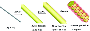
Caterpillar-like (CL) Au/Ag nanotubes (NTs) with high surface roughness were synthesized by a simple, rapid route using silver nanowires as sacrificial template and 3,4-dihydroxyphenylalanine (DOPA) as reducing and capping agent. Further experiments revealed that, by simply varying the ratios of the chlorauric acid and DOPA, the surface roughness of the CL Au/Ag NTs could be well controlled. The scanning electron microscope and transmission electron microscopy characterizations confirmed that the main NTs were polycrystalline, whereas the spines on their surface were single crystals. The hollow interior of the NTs was ascribed to the occurrence of the Kirkendall effect during the galvanic reaction between the metallic silver and AuCl4. The formation of the spines results from the AgCl induced anisotropic growth of gold species. Because of their unique structures, such as a prickly surface and hollow internal tube, the as-prepared CL Au/Ag NTs exhibited a sensitive and reproducible performance in surface enhanced Raman scattering.


Introduction

Surface enhanced Raman scattering (SERS) spectroscopy can effectively respond to the structural information of a molecule and has been widely applied in analytical chemistry, as a biochemical sensor, for environmental monitoring, and for single molecule and biomedical detection.1–7 The intensified electromagnetic (EM) field oriented from the excitation of its localized surface plasmon resonance (LSPR) in noble or transition metals such as gold (Au), silver (Ag) and copper (Cu), contributes greatly to SERS enhancement. The nanoscale junctions on the surface of gold or silver nanostructures are active sites which produce tremendous field enhancement because of the EM field being localized in these “points”.8–10 Thus, the SERS signals can be significantly amplified by nanoscale surface roughness. Therefore, in recent years, great efforts have been made to design and synthesize noble metal nanostructures with a rough surface,11–17 because the nanojunctions can be generated at sharp edges, corners, and gaps between nanoparticles or nanotips.3,15,18–21 Typically, a series of anisotropic, spiky nanoparticles, such as nanostars,22,23 nanoflowers24,25 and sea urchin/meatball-like nanoparticles,14,15,26 have been synthesized. Compared to the smooth Au or Ag particles of a similar size, these spiky particles, without exception, presented a great enhancement in SERS from individual particles.

Besides the sensitivity, the other particular problem specific to SERS is to prepare enhancing media that are reproducible.6 Although this serious impediment to SERS applications has been partly resolved by fabricating the periodic nanostructures using nanometer scale lithography techniques,27,28 it is obvious that such techniques are not readily available and affordable for practical applications. Recent research has revealed that the reproducibility of SERS can be achieved from the individual or assembly of mesoscopic Au or Ag particles or nanowires (NWs) with a rough surface.8–10,18 Xu and co-workers found that the characteristics of the rough surface made the flower-like Au and Ag mesoparticles the ideal SERS substrates with improved reproducibility.9,25 But it is noteworthy that the Raman spectra varied with laser irradiation time and different particles. This was tentatively attributed to the inhomogeneous absorption of analyte molecules on different particles induced by their intrinsic shape difference and the SERS blinking effect observed in the single molecule or single particle SERS systems.9,29–31 The one-dimensional Ag and Au NWs or nanorods offered a homogeneous platform for both structure and analyte absorption, and their large surface areas made them reproducible SERS substrates for reliable sensing applications.16,32–34 However, the smooth metallic wire could hardly couple to light because of the mismatch between the photon and the wire plasmon dispersion relationship.35 Thus, in order to increase the surface roughness of NWs, Ling and co-workers presented a chemical etching method to create undulating ridges on the surface of the Ag NWs, which produced more homogeneous SERS active hot spots distributed along the Ag NW's longitudinal axis.18 Vigderman and Zubarev synthesized starfruit-shaped Au nanorods and NWs using a seed-mediated approach.33 The uniquely periodic starfruit-like morphology generated more hot spots, which were responsible for a higher SERS performance compared to the smooth NWs.

In this paper, a two-step growth method is presented to synthesize the caterpillar-like (CL) Au/Ag nanotubes (NTs) with a high density of nanometer-sized spines on the entire length of their surface. Firstly, a polyol method is used to synthesize Ag NWs with an average diameter of about 40 nm. Secondly, these NWs subsequently serve as both sacrificial templates and seeds for the synthesis of CL Au/Ag NTs. The SERS measurement from a single NT indicated that the increased and reproducible SERS signals measured over the entire length of the NT results from the homogeneous distribution of spines on the entire length of the CL Au/Ag NTs, which acts as the nanoantenna inducing an efficient light coupling.

Experimental

Synthesis of silver nanowires

In a typical synthesis,36 1,2-propylene glycol (1,2-PG, 10 mL) that contained poly(vinyl pyrrolidone) (PVP, MW ≈ 50[thin space (1/6-em)]000, 150 mM as calculated in terms of the repeating unit) was placed in a 25 mL vial, capped, and heated with stirring in an oil bath at 160 °C for 1 h. Then, 1 mL of NaCl solution (1 mM in 1,2-PG) was quickly added. After 5 min, AgNO3 (0.15 M solution in 1,2-PG, 4 mL) was added dropwise to the stirring solution. The vial was then capped and heated at 160 °C for 40 min. The product (about 14 mL) was divided into seven aliquots and separated from the solution using centrifugation. The free PVP molecules were removed by centrifuging at 4000 rpm for 3 min and the Ag nanowires was dispersed into 14 mL of ultrapure water.

Synthesis of CL Au/Ag NTs

In a typical synthesis of CL Au/Ag NTs,37 0.5 mL of a colloidal solution of Ag NW was mixed with 13.5 mL of water in a 25 mL glass vial with a rotating magnetic bar at a speed of 500 rpm. Then 1.5 mL of chlorauric acid (HAuCl4) (50 mM) was quickly added. After 30 s, 5 mL of an aqueous solution of 3,4-dihydroxyphenylalanine (DOPA) (10 mM) was added immediately. After 10 min, the final product was centrifuged, rinsed with distilled water several times.

Characterization techniques

The X-ray diffraction (XRD) patterns were obtained using a Bruker D8 ADVANCE X-ray diffractometer with a Cu Kr X-ray source. Scanning electron microscope (SEM) images were obtained using a Jeol JSM 7000F instrument. Transmission electron microscopy (TEM) and high-resolution transmission electron microscopy (HRTEM) images were obtained using a Jeol JEM 3010 instrument.

SERS measurement and simulation

SERS measurements were carried out using a HORIBA Jobin Yvon LabRAM HR800 confocal microprobe Raman spectrometer with the 633 nm He–Ne laser line at room temperature. The probe area was 1 μm in diameter with a 100× objective lens and the signal collection time was 10 s. The incident power of the laser at the sample was 0.055 mW after it was decreased by a D2 attenuation piece. The products were transferred onto a cleaned quartz plate for SERS sample preparation. Samples for SERS were prepared by soaking overnight in 10 mL aqueous solution of 1 × 10⁻⁵ M rhodamine 6G (R6G), then the residual solution was washed with deionized water and the solvent was allowed to evaporate.

A commercial simulation program (FDTD solutions 8.6.4, Lumerical Solutions, Vancouver, Canada) was used to simulate the EM-field properties of the nanostructures. We developed a cylinder with a hollow interior as a substitute for the main structure without including the outside spines of the Au/Ag NTs. The inner and outer diameters were 50 nm and 500 nm, respectively. Rounded tip cones were chosen to simulate the spines on the surface of the hollow cylinder. The lengths of the spines were not identical, but the distribution of spines was uniform. The spines were simplified to rounded tip cones with a length of 50 nm and a bottom diameter of 25 nm. Considering the high aspect ratio of the SEM images (Fig. 2), the length along the long axis of the Au NT was set to 1 μm in the simulation. The permittivity of Au was taken from ref. 15.


image file: c4ra07971j-f1.tif
Fig. 1 Characterization of the Ag NWs synthesized by the 1,2-PG reduction method. Low (a) and high (b) magnification SEM images of Ag NWs; (c) TEM image of the sample; (d) XRD patterns and energy dispersive spectroscopy (EDS) spectrum of sample.

image file: c4ra07971j-f2.tif
Fig. 2 (a) and (b) SEM images of CL Au/Ag NTs; (c) TEM image of a single CL Au/Ag NTs; (d) SAED pattern taken from (c); (e) the enlarged TEM image of the spines on the surface of Au/Ag NTs; (f) the HRTEM image of a single spike. The insert in (b) shows the cross-sectional SEM image of the CL Au/Ag NTs after high power ultrasonic processing.

Results and discussion

The Ag NWs were synthesized using the so-called polyol method as previously reported by Bi et al.36 Fig. 1a and c show the SEM and TEM images of the as-synthesized Ag NWs, which show a long and smooth morphology with a uniform diameter throughout the length of the NW. The average diameter is estimated to be about 40 nm. The enlarged SEM image on the sectional view of the nanowires (insert in Fig. 2b) further reveals that they have a typical pentagonal cross-section, indicating that the NWs are formed by multiple twinned particles of a typical 5-fold symmetry.37 The XRD pattern (Fig. 1d) of the Ag NWs indicates a typical face-centered cubic (fcc) structure of the product. No other diffraction peak was observed, indicating that these products are pure phase, which is coincident with the characterization result of EDS spectra (insert in Fig. 1d).

DOPA, a natural amino acid which is present in mussel adhesive proteins, has been reported to be an efficient reducer and capping agent for the preparation of core–shell Au@DOPA hybrid nanospheres and urchin-like Au submicrostructures in aqueous solution at room temperature.38,39 In this research, the CL Au/Ag NTs with a prickly surface were synthesized at room temperature and DOPA was used as a reducing and capping agent and the as-prepared Ag NWs were used as the sacrificial template. Fig. 2a shows the SEM image of the CL Au/Ag NTs synthesized by a two-step method (the galvanic reaction (GR) combined with the DOPA reducing). As one can see the NTs present a prickly surface, very similar to that of a caterpillar (insert in Fig. 2a). The insert in Fig. 2b shows the cross-sectional SEM image of the CL Au/Ag NTs after high power ultrasonic processing. It clearly presents a hollow interior, indicating that the GR occurred between the metallic Ag NWs and the AuCl4 during the first step, which induced the formation of the hollow interior of the NTs.40,41 The average diameter of the products measured from the SEM images is about 250 nm, which is six times higher than that of the initial Ag NW template used, indicating the further growth of the prickly layer on the surface of NTs. The selected area electron diffraction (SAED) pattern indicates that the structure of the CL Au/Ag NTs is polycrystalline. The four SAED rings can be approximately indexed to the {111}, {200}, {220}, and {311} lattice planes of Au (Fig. 2d). The HRTEM image shows a randomly oriented spine with a tip of about 8 nm diameter (Fig. 2c). The lattice spaces (labeled in the HRTEM image), were 0.203 nm, which can be indexed as the {200} planes of Au. The measured angle between the {200} and {111} plane was 55°, which was equal to the calculated value, indicating that the growth of the spines is along the 〈111〉 direction, as labeled by the arrow in Fig. 2f.

The elemental distribution of the as-synthesized products was studied using high-angle annular dark-field scanning transmission electron microscopy (HAADF-STEM) and energy dispersive spectroscopy (EDS) (line scans and elemental mapping images), as shown in Fig. S1 in the ESI. The elemental mapping of a single CL Au/Ag NT reveals that the NT appears to be mainly composed of Au. The weak signals resulting from the elemental Ag are also found to be distributed throughout the entire NT, indicating that a small amount of silver is being alloyed in the final structure during the GR and growth process.

The formation process of CL Au/Ag NTs was investigated by analyzing the product obtained after adding different concentrations of DOPA and HAuCl4. As shown in Fig. 3, the morphology and the growth of spines on the surface of the NTs were obviously affected by the concentration of DOPA and HAuCl4. The mole ratio of DOPA to HAuCl4 was kept at 1[thin space (1/6-em)]:[thin space (1/6-em)]1 in whole synthesis process. As shown in Fig. 3a, when the feeding amount of DOPA and HAuCl4 was 1.5 mM, Au/Ag NTs with a rough, rather than a prickly surface were obtained, indicating the AuCl4 ions were being consumed in the initial GR that occurred between silver and the AuCl4 ions. Thus, not enough AuCl4 ions existed in the solution to support the further growth of the spines. As shown in Fig. 3b and c, an increase in the amount of DOPA and HAuCl4 obviously improved the growth of spines on the surface of the NTs. The diameter of the tubes also increased when the feeding amount of DOPA and HAuCl4 increased from 2.5 to 3.25 mM, indicating that both the density and length of the spines can be controlled by varying the amount of additives, i.e., DOPA and HAuCl4. Fig. 3d shows the EDS analysis results obtained from the corresponding samples. The linear relationship of the Au in the final products with the amount added reveals that the ionic Au precursor has been completely reduced.


image file: c4ra07971j-f3.tif
Fig. 3 The SEM images of the product prepared using different concentration ratios of HAuCl4/DOPA and Ag NWs: (a) 1.5, (b) 2.5 and (c) 3.25 mM. (d) The relationship between the atomic percentage of Au in the final products and concentration of HAuCl4/DOPA. The amount of Ag NWs is 0.5 mL. The scale bar is 1 μm.

On the basis of the previous discussions, the formation mechanism of the CL Au/Ag NTs can be illustrated by the schematic drawing in Fig. 4. At the initial stage, the GR between Ag0 and AuCl4 was dominant, because DOPA was not added yet, which induced the occurrence of the Kirkendall effect and the formation of hollow Au/Ag NTs. Meanwhile, the GR between Ag and AuCl4 generated AgCl, which has a low solubility in water and precipitates out from the solution and preferentially deposits on the surface of the Au/Ag NTs.42,43 It has been reported previously that the AgCl formed and/or the AgBr precipitates on the noble metal nanoparticles, such as Au, platinum and Ag, could promote the nonepitaxial growth of those noble metals on AgCl sites.36,42,44–46 In the current case, after the addition of DOPA into the solution, the residual AuCl4 ions were reduced to Au0. Then, the heterogeneous nucleation and growth of Au on the AgCl generated in situ will be prominent, inducing the subsequent growth of the Au spines from these nucleation sites. Similarly, when the spherical Ag nanoparticles were used as the template, the sea urchin-like spherical Au/Ag nanoparticles with a prickly surface can be synthesized (Fig. S2 in the ESI). This indicated that this method is a simple and universal route to prepare the prickly nanostructures.


image file: c4ra07971j-f4.tif
Fig. 4 A representation of the formation mechanism for the CL Au/Ag NTs.

The SERS performance of the CL Au/Ag NT was studied using R6G molecules as the adsorbate. Fig. 5 shows the SERS signals recorded at different sites on a single Au/Ag NT that was treated with R6G solution at a concentration of 10−5 M. Many salient signals were clearly observed and the pronounced peaks at 1357, 1511, and 1650 cm−1 can be assigned to the totally symmetric modes of in-plane C–C stretching vibrations.47 To avoid the particle coupling interfering with the measurement, the chosen NW was at least several micrometers away from its neighbours.18 The measurement intervals along NTs were kept at around 0.5 μm, as approximately labeled in the optical image in Fig. 5. It clearly indicates that the SERS signals collected from the selected points along the whole NT show almost the same intensities. Compared with the smooth NWs on which the Raman active sites were only localized at the two ends because of the strong scattering of light at the sharp tips of the NWs, as previously reported by Ling and co-workers,18 the hot spots are distributed over the entire prickly Au/Ag NT. This can be attributed to the spines uniformly growing on the surface of NTs which induce the antenna effects on the entire surface of the NTs.


image file: c4ra07971j-f5.tif
Fig. 5 SERS spectra at different sites on a prickly Au/Ag NT. R6G (10−5) was used as the Raman dye. The sites 1–9 are shown in the inset.

Fig. 6 shows a comparative study of the SERS performance of Au/Ag NTs with or without spines. The SERS signals were recorded from the center part of a single NT (inserts in Fig. 6a). The surface enhancement factors (EF) at a wavelength of 1362 cm−1 were simply calculated based on the measured results from the equation of EF = (ISERS × CRaman)/(IRaman × CSERS), where I and C represent the intensity and concentration, respectively.48 The calculated EF values of the NT with and without spines were around 105 and 104 respectively. These results indicate that the contribution of spines is very powerful for SERS intensity.


image file: c4ra07971j-f6.tif
Fig. 6 SERS of CL Au/Ag NTs with spikes and no spikes. R6G (10−5 M) was used as the adsorbate.

The spatial distribution of electric field of hollow Au/Ag NT with or without spines was studied by three-dimensional finite-difference time-domain (3D-FDTD) simulations to make a direct comparison with the experimental SERS results.49 A total-field/scattered-field plane wave source (TSTF source) with the wavelength of 632.8 nm was selected to estimate the interaction between propagating plane wave and metallic nanostructures. Incident direction was perpendicular to the long axial direction of Au/Ag NT with nanospines. The direction of polarization was perpendicular to the incident plane which included both incident direction and long axial direction. Boundary conditions were set with six perfectly matched layers (PMLs) which could make our simulations a proper convergence. At the same time, conformal grid technology was utilized to improve the accuracy and economize computational memory. The mesh size of the override mesh region was set to be 1 nm to cover the entire structure. Here two field monitors (frequency-domain field profile monitor) were imported to record the spatial distribution of electric field. One was placed in the centre of the model and normal to the axial direction of the Au/Ag NT. The other was put in the middle of structures and perpendicular to the incident wave direction. We calculated the average maximum value of the square of the local electric field intensity as shown in Fig. 7 (b, c, e and f). As shown in Fig. 7b and c, the laser irradiation induced LSP modes on the metal surface results in a larger EM field, which uniformly distributed on the surface of spiky Au/Ag NTs. The electric field distribution of the spiky Au/Ag NTs from the simulation is consistent with the results of experimental Raman test (Fig. 5), in which the SERS signals measured from along the whole NT show almost the same intensities. While for the roughed Au/Ag NT without spines, high EM field in simulation were observed only at both ends of NT, which is similar with the results measured from the solid Ag nanowires.18


image file: c4ra07971j-f7.tif
Fig. 7 The spatial distribution of the electric field obtained by 3D-FDTD simulation. (a, d) Schematic representation of Au/Ag NT with gold nanospines and Au/Ag NT with a roughened surface. (b, c, e, f) Spatial distribution of the electric field intensity of plane perpendicular to the long axial direction of Au/Ag NT and perpendicular to the incident direction corresponding to (a) and (d) at the wavelength of 632.8 nm. In all simulations, the direction of the incident light was perpendicular to the long axial direction of Au/Ag NT with gold nanospines or Au/Ag NT with a roughened surface.

Conclusions

We demonstrated a facile and efficient process for the synthesis of CL Au/Ag NTs, in which the solid Ag nanowires were used as the sacrificial template and DOPA was used as both reducer and structure-induce-growth agent. The SERS performance of the CL Au/Ag NTs was highly dependent on their surface roughness. Typically, the spiky NTs presented an increased and reproducible SERS signal over the entire length of NTs due to the homogeneous distribution of spines on their surface, which may endow them as an ideal SERS-active substrate for organic chemical molecules or biodetection.

Acknowledgements

We thank Ms. Yanzhu Dai from the International Center for Dielectric Research, Xi’an Jiaotong University (XJTU), for her support with SEM. We also thank Prof. Liqing Huang from the School of Science, XJTU, for her support with the simulation program. This work is supported by National Natural Science Foundation of China (no. 51271135), the program for New Century Excellent Talents in university (no. NCET-12-0455), the Fundamental Research Funds for the Central Universities and National Key Technology Research and Development Program of the Ministry of Science and Technology of China (no. 2012BAE06B08), and the project of Innovative Team of Shaanxi Province (no. 2013KCT-05).

Notes and references

  1. J. F. Li, Y. F. Huang, Y. Ding, Z. L. Yang, S. B. Li, X. S. Zhou, F. R. Fan, W. Zhang, Z. Y. Zhou and D. Y. Wu, Nature, 2010, 464, 392–395 CrossRef CAS PubMed.
  2. M. Fan, G. F. S. Andrade and A. G. Brolo, Anal. Chim. Acta, 2011, 693, 7–25 CrossRef CAS PubMed.
  3. L. Tong, T. Zhu and Z. Liu, Chem. Soc. Rev., 2011, 40, 1296–1304 RSC.
  4. X. M. Qian and S. M. Nie, Chem. Soc. Rev., 2008, 37, 912–920 RSC.
  5. E. J. Smythe, M. D. Dickey, J. Bao, G. M. Whitesides and F. Capasso, Nano Lett., 2009, 9, 1132–1138 CrossRef CAS PubMed.
  6. S. E. J. Bell and N. M. S. Sirimuthu, Chem. Soc. Rev., 2008, 37, 1012–1024 RSC.
  7. S. M. Yoo, T. Kang, H. Kang, H. Lee, M. Kang, S. Y. Lee and B. Kim, Small, 2011, 7, 3371–3376 CrossRef CAS PubMed.
  8. X. Gong, Y. Bao, C. Qiu and C. Jiang, Chem. Commun., 2012, 48, 7003–7018 RSC.
  9. Q. Li, Y. Jiang, R. Han, X. Zhong, S. Liu, Z.-Y. Li, Y. Sha and D. Xu, Small, 2013, 9, 927–932 CrossRef CAS PubMed.
  10. H. Liang, Z. Li, Z. Wang, W. Wang, F. Rosei, D. Ma and H. Xu, Small, 2012, 8, 3400–3405 CrossRef CAS PubMed.
  11. W. Kubo and S. Fujikawa, Nano Lett., 2011, 11, 8–15 CrossRef CAS PubMed.
  12. D. He, B. Hu, Q.-F. Yao, K. Wang and S.-H. Yu, ACS Nano, 2009, 3, 3993–4002 CrossRef CAS PubMed.
  13. S. Yang, F. Xu, S. Ostendorp, G. Wilde, H. Zhao and Y. Lei, Adv. Funct. Mater., 2011, 21, 2446–2455 CrossRef CAS.
  14. H. You, Y. Ji, L. Wang, S. Yang, Z. Yang, J. Fang, X. Song and B. Ding, J. Mater. Chem., 2012, 22, 1998–2006 RSC.
  15. S. Pedireddy, A. Li, M. Bosman, I. Y. Phang, S. Li and X. Y. Ling, J. Phys. Chem. C, 2013, 117, 16640–16649 CAS.
  16. M. Chen, I. Y. Phang, M. R. Lee, J. K. W. Yang and X. Y. Ling, Langmuir, 2013, 29, 7061–7069 CrossRef CAS PubMed.
  17. S. Yang and X. Luo, Nanoscale, 2014, 6, 4438–4457 RSC.
  18. M. S. Goh, Y. H. Lee, S. Pedireddy, I. Y. Phang, W. W. Tjiu, J. M. R. Tan and X. Y. Ling, Langmuir, 2012, 28, 14441–14449 CrossRef CAS PubMed.
  19. X. Yu, X. Wan, L. Wang, Z. Yang, B. Ding and S. Yang, Mater. Res. Express, 2014, 1, 015024 CrossRef.
  20. S. Yang, X. Wan, Y. Ji, L. Wang, X. Song, B. Ding and Z. Yang, CrystEngComm, 2010, 12, 3291–3295 RSC.
  21. X. Luo, S. Lian, L. Wang, S. Yang, Z. Yang, B. Ding and X. Song, CrystEngComm, 2013, 15, 2588–2591 RSC.
  22. S. Mazzucco, O. Stephan, C. Colliex, I. Pastoriza-Santos, L. M. Liz-Marzan, J. Garcia de Abajo and M. Kociak, Eur. Phys. J.: Appl. Phys., 2011, 54 Search PubMed.
  23. P. Senthil Kumar, I. Pastoriza-Santos, B. Rodriguez-Gonzalez, F. J. Garcia de Abajo and L. M. Liz-Marzan, Nanotechnology, 2008, 19 Search PubMed.
  24. Y. Jiang, X.-J. Wu, Q. Li, J. Li and D. Xu, Nanotechnology, 2011, 22 CAS.
  25. H. Liang, Z. Li, W. Wang, Y. Wu and H. Xu, Adv. Mater., 2009, 21, 4614–4618 CrossRef CAS.
  26. H. Wang and N. J. Halas, Adv. Mater., 2008, 20, 820–825 CrossRef CAS.
  27. I. Sow, J. Grand, G. Levi, J. Aubard, N. Felidj, J. C. Tinguely, A. Hohenau and J. R. Krenn, J. Phys. Chem. C, 2013, 117, 25650–25658 CAS.
  28. C. L. Haynes, A. D. McFarland and R. P. Van Duyne, Anal. Chem., 2005, 77, 338A–346A CrossRef CAS.
  29. Z. J. Wang and L. J. Rothberg, J. Phys. Chem. B, 2005, 109, 3387–3391 CrossRef CAS PubMed.
  30. J. T. Krug, G. D. Wang, S. R. Emory and S. M. Nie, J. Am. Chem. Soc., 1999, 121, 9208–9214 CrossRef CAS.
  31. S. M. Nie and S. R. Emery, Science, 1997, 275, 1102–1106 CrossRef CAS PubMed.
  32. P. Mohanty, I. Yoon, T. Kang, K. Seo, K. S. K. Varadwaj, W. Choi, Q. H. Park, J. P. Ahn, Y. D. Suh, H. Ihee and B. Kim, J. Am. Chem. Soc., 2007, 129, 9576–9577 CrossRef CAS PubMed.
  33. L. Vigderman and E. R. Zubarev, Langmuir, 2012, 28, 9034–9040 CrossRef CAS PubMed.
  34. B. Peng, G. Li, D. Li, S. Dodson, Q. Zhang, J. Zhang, Y. H. Lee, H. V. Demir, X. Y. Ling and Q. Xiong, ACS Nano, 2013, 7, 5993–6000 CrossRef CAS PubMed.
  35. H. Wei, F. Hao, Y. Huang, W. Wang, P. Nordlander and H. Xu, Nano Lett., 2008, 8, 2497–2502 CrossRef CAS PubMed.
  36. Y. Bi, H. Hu and G. Lu, Chem. Commun., 2010, 46, 598–600 RSC.
  37. Y. G. Sun, B. Mayers, T. Herricks and Y. N. Xia, Nano Lett., 2003, 3, 955–960 CrossRef CAS.
  38. W.-G. Qu, S.-M. Wang, Z.-J. Hu, T.-Y. Cheang, Z.-H. Xing, X.-J. Zhang and A.-W. Xu, J. Phys. Chem. C, 2010, 114, 13010–13016 CAS.
  39. F. Xu, K. Cui, Y. Sun, C. Guo, Z. Liu, Y. Zhang, Y. Shi and Z. Li, Talanta, 2010, 82, 1845–1852 CrossRef CAS PubMed.
  40. Y. G. Sun and Y. N. Xia, J. Am. Chem. Soc., 2004, 126, 3892–3901 CrossRef CAS PubMed.
  41. Y. G. Sun, B. Mayers and Y. N. Xia, Adv. Mater., 2003, 15, 641–646 CrossRef CAS.
  42. H. Yuan, W. Ma, C. Chen, J. Zhao, J. Liu, H. Zhu and X. Gao, Chem. Mater., 2007, 19, 1592–1600 CrossRef CAS.
  43. W. Zhang, J. Yang and X. Lu, ACS Nano, 2012, 6, 7397–7405 CrossRef CAS PubMed.
  44. C. J. Murphy, T. K. San, A. M. Gole, C. J. Orendorff, J. X. Gao, L. Gou, S. E. Hunyadi and T. Li, J. Phys. Chem. B, 2005, 109, 13857–13870 CrossRef CAS PubMed.
  45. W. M. Schuette and W. E. Buhro, ACS Nano, 2013, 7, 3844–3853 CrossRef CAS PubMed.
  46. H. Yuan, W. Ma, C. Chen, H. Zhu, X. Gao and J. Zhao, J. Phys. Chem. C, 2011, 115, 23256–23260 CAS.
  47. J. A. Dieringer, K. L. Wustholz, D. J. Masiello, J. P. Camden, S. L. Kleinman, G. C. Schatz and R. P. Van Duyne, J. Am. Chem. Soc., 2009, 131, 849–854 CrossRef CAS PubMed.
  48. D. Choi, Y. Choi, S. Hong, T. Kang and L. P. Lee, Small, 2010, 6, 1741–1744 CrossRef CAS PubMed.
  49. J. Q. Lu, P. Yang and X. H. Hu, J. Biomed. Opt., 2005, 10 CAS.

Footnote

Electronic supplementary information (ESI) available: HADDF and element distribution image along a straight line elements distribution of caterpillar-like Au–Ag nanorods (Fig. S1). SEM image of the sea-urchin-like gold nanoparticles synthesized with spherical Ag NPs as sacrificial template (Fig. S2). See DOI: 10.1039/c4ra07971j

This journal is © The Royal Society of Chemistry 2014