Polybutene-1 tube with in situ microfibering polystyrene via helical convergent flow: an economical pathway to continuously fabricate biaxially reinforced polyolefin tubes for medical application

Wei Liu, Min Nie* and Qi Wang
State Key Laboratory of Polymer Materials Engineering, Polymer Research Institute of Sichuan University, Chengdu 610065, China. E-mail: poly.nie@gmail.com; Fax: +86-28-85405133; Tel: +86-28-85405133

Received 16th July 2014 , Accepted 17th September 2014

First published on 17th September 2014


Abstract

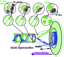
Polystyrene (PS) microfibers with high molecular orientation and helical alignment were in situ formed via helical convergent flow during polybutene-1 (PB-1) tubing processing to achieve performance improvements in both axial and hoop directions, which opened up an economical pathway for continuous fabrication of biaxially reinforced polyolefin tubes for medical application.


Polymeric medical devices, e.g. tubes and catheters, have been indispensable for the treatment of critical cases since they offer additional and essential advantages such as ease of manufacturing, low cost, and disposability.1 Being amenable to gamma and electron beam radiation sterilization and effectively reducing the occurrence of infectious diseases, polyolefin-based single-use products are considered as the most promising and recommended polymeric devices for medical use.2,3

The mass production of polyolefin tubes or catheters, i.e., extrusion, shows two significant defects: the weld line issue and the axial orientation, exposing flaws in lessened mechanical performances in the hoop direction.4 Given that the hoop stress imposed on the pressurized tubes is twice as high as the axial stress in their actual use, the cracks tend to generate at welded joints and propagate along the axial direction, leading to the deformation and final failure of polyolefin tubes.5,6 When a tube is being employed to infuse patients with drugs or implanted as catheters or artificial tracheas, the failure of the devices could cause serious damage and infection to the patient.7

Aiming at improving the mechanical performances of a given polymer products, it is typical to introduce fibers and other fillers as reinforcing components.8,9 Nevertheless, the reinforcement direct-filling technique encounters the difficulty of implementing continuous large-scale production, as well as poor dispersion of the filler.10 As a relatively new technique to modify polymeric materials, in situ microfibrillation has been arousing widespread research interests.10,11 Under appropriate conditions (basically stretching under proper temperature), the dispersed phase can be induced to form microfibrillar structure with tinny diameter and large aspect ratio, which substantially enhances the mechanical performances.12 And yet, this three-step (blending–drawing–isotropization) technique, also met the limitation of efficiency and continuity. Besides, it is still a huge challenge to manipulate the alignment of the formed microfibers, which is a key factor to the end-use property of produced tubes especially when the perpendicular-to-extrusion-direction mechanical properties are preferred, since the in situ formed fibers are universally aligned parallelly to the drawing or extrusion direction.13,14

Polybutene-1 (PB-1), a semi-crystalline polyolefin, finds potential application in medical tubing or piping offering advantages in terms of good resistance to chemicals and excellent creep properties even at elevated temperature.15,16 In this communication, utilizing a novel in situ microfibrillar candidate: polystyrene (PS), combined with a unique tubular convergent flow introduced to the off-die melt, the dispersed PS phase in the PB-1 matrix can be transformed into microfibers with high aspect ratio and high molecular orientation. Moreover, imposing the tubular-convergent-flowing melt with an off-die relative hoop motion, the alignment of microfibers can be controlled. By manipulating the morphology and alignment of PS microfibers, PB-1 tubes with enhanced mechanical properties in both axial and hoop direction were produced. This research provides an one-step microfibrillation technique and an economical and versatile strategy to mass-manufacture polymer tubes with superior mechanical performances.

The granules of PB-1 and PS were pre-mixed in a weight ratio of 90/10 after being dried at 80 °C for 30 min. By introducing a extensional convergent flow to the off-die melt with different convergent flow ratio (CFR), which was defined as the ratio of melt flow velocity after and before convergence (image file: c4ra07193j-t1.tif, where V2 and V1 were the melt flow velocity in the sizing sleeve and the die respectively), tubes with different CFR were prepared to determine the optimal condition for the formation of PS microfibers. The common blend tubes, which no convergent flow was applied to, were also prepared by taking the extrudates directly off the die. To manipulate the alignment of the in situ formed PS microfibers, a relative motion was imposed to the off-die melt by the counter rotating mandrel and die, i.e. rotation extrusion.17 In this communication, the rotation rates of mandrel and die were both set at 4 rpm and the CFR was set at 3.4 to control the formation and alignment of the microfibrillation. The PS/PB-1 and pure PB-1 tubes prepared through rotation extrusion were denoted as RE-PSPB and RE-PB. And those tubes prepared through convention extrusion, during which the mandrel and die remain motionless, were denoted as CE-PSPB and CE-PB, respectively [detailed description of raw materials, fabrication methods and characterizations are provided in ESI].

The phase morphology of the composite tubes produced via different CFR was firstly investigated by SEM observation (As shown in Fig. 1). After selectively etching the PB-1 phase with a permanganic etchant,18 the morphology of PS phase could be well preserved and exposed due to its good resistance to the mixed acid.19 As can be seen from the SEM pictures, the PS phase seems to undergo a series of flow-induced morphological evolution with the increase of CFR. Under the action of extensional convergent flow (CFR = 1.09), the PS phase tended to firstly adhered together to form aggregates (Fig. 1b) from isolated spherical droplets (Fig. 1a). Different from the in situ microfibrillation techniques developed by other researchers,11,12,14 in this case the PS phase showed extra-fine fluidity due to the high processing temperature during microfibrillating in this communication, which would led to the flow-field-induced droplets' agglomeration.20 What's more, besides the velocity-change-caused shear and elongational stress applied to dispersed phase, which could be the driving force of phase deformation, the dramatically shrinking transection area of the melt (another noteworthy feature of convergent flow) would provide considerable probability for phase collision and coalescence. Given that the length & volume of a single microfiber is much longer & bigger than each dispersed droplet (as can be seen in Fig. 1), the colliding and coalescing of the dispersed droplets could be regarded as the prerequisite for the formation of microfibers, which is in well accordance with other searcher's findings.12–14,20 As the CFR continued to increase to 3.4, the spindle-like aggregates were exerted on the rapidly growing shear and elongational stress, resulting in elongational deformation and collapse of PS “spindles”, and eventually, the high-aspect-ratio PS microfibers formed (as shown in Fig. 1c, c1, d and d1). More importantly, homogeneous distribution (observed at low magnification) and uniform diameters (seen in high magnification) of the microfibers were simultaneously achieved.


image file: c4ra07193j-f1.tif
Fig. 1 SEM pictures of PS/PB-1 tubes produced via different convergent flow ratio conditions, (a) common blend, (b) CFR = 1.09, (c) and (c1) CFR = 3.4 at flow plane; (d) and (d1) CFR = 3.4 at transection perpendicular to flow direction. Extrusion direction vertical for (a), (b), (c) and (c1).

Looking at the structural change in a more microscopic scale, i.e. the crystal lattices and molecular chains, we found more interesting results (as shown in Fig. 2). 2D-WAXD patterns of the neat PB-1 tubes and microfibrillar PS/PB-1 composite tubes (all produced when CFR was fixed at 3.4 to achieve optimal microfibrillating) shows uniform diffraction rings, which means no oriented crystals was formed during current flow condition. Given that the PB-1 was the only crystalline component in present system, which was in well accordance with the (220), (300) and (110) diffraction peaks observed in Fig. 2a & b, it can be concluded that the PB-1 did not form oriented structure. However, the 2D-SAXS patterns of the PS/PB-1 composite tubes (Fig. 2d) clearly showed a sharp streak signal in the equator direction, which was not observed in the neat PB-1 samples produced via the same CFR. This streak signal in 2D-SAXS patterns was universally established as the “shish” structure, that is, the extended and aligned molecule bundles.21,22 What's more important, this “shish” structure should not be ascribed to PB-1 molecules, otherwise the streak would appear in the 2D-SAXS patterns of neat PB-1 samples (Fig. 2c) and anisotropic intensity arcs would be observed in 2D-WAXD patterns (Fig. 2a and b). So the only rational explanation would be ascribed to the reorganization of PS molecules, which is non-crystalline and leaves no trace in 2D-WAXD tests. The formation of extended and aligned PS molecule bundles induced by convergent flow field, which are amorphous, could create regions of different electron density with sufficient contrast that can be detected by 2D-SAXS and manifested as the equatorial streak.23,24 Further modeled all the azimuthal distributions with Lorentz functions and related the observed azimuthal width (Bobs) to the length of the “shish” structure (〈Lshish〉),21,22 we quantitatively calculated the “shish” structure to be of ∼420 nm length [detailed calculation described in ESI]. Clearly, this is the molecular chain segmental orientation since the molecular length of PS used in this study could be estimated to be far more than hundreds of nanometers.


image file: c4ra07193j-f2.tif
Fig. 2 2D-WAXD (a) and (b) and 2D-SAXS (c) and (d) patterns of neat PB-1 tubes (a) and (c) and PS/PB-1 composite tubes (b) and (d) produced at fixed CFR of 3.4. Extrusion direction vertical.

It is evident the high-aspect-ratio PS microfibers with high molecular orientation could be very promising as a reinforcement, since the high-modulus PS microfibers can effectively bear and transmit stress along the fiber axis direction, i.e., in this case of study, the axial direction. However, when the stress was applied in the direction perpendicular to the fiber axis, these microfibers could no longer be reinforcements since the cracks could easily generate and propagate along the fiber interfaces. In order to manipulate the alignments of the microfibers, an off-die relative hoop motion was imposed to the convergent-flowing melt by a set of counter rotating mandrel and die. As can be seen from Fig. 3, PS microfibers with high aspect ratio universally formed when fixing the CFR at 3.4. For PS/PB-1 composite tubes produced via conventional extrusion with immobile mandrel and die, the PS microfibers in both the inner & outer wall (Fig. 3a & b) were universally aligned along the extrusion direction. Nevertheless, after superimposing an off-die hoop motion onto the convergent-flowing melt, the flow form was changed from sole convergent flow to a helical convergent flow, leading to the deviation of the PS microfibers' alignment off the axial direction (Fig. 3c & d), as illustrated in Fig. 4.


image file: c4ra07193j-f3.tif
Fig. 3 The SEM pictures of PS microfibers generated via different extrusion methods when fixing the CFR at 3.4; (a) and (b) inner and outer wall of the conventional extrusion (CE), (c) and (d) inner and outer wall of the rotation extrusion (RE). Extrusion direction vertical as indicated by the arrow beside.

image file: c4ra07193j-f4.tif
Fig. 4 Illustration of structural evolution during helical convergent flow.

Given that the high-aspect-ratio PS microfibers with high molecular orientation were formed and their alignment was well manipulated, large differences in mechanical properties of the neat PB-1 and PS/PB-1 composites tubes prepared via different flow models could occur. As shown in Fig. 5, the PS/PB-1 composites tubes prepared via sole convergent flow with CFR fixed at 3.4, under which condition the high-aspect-ratio microfibers universally formed and aligned axially, shows a significant improvement in the ultimate axial strength (UAS) and reaches 41.3 Mpa, increases by 38.1% as compared to the neat PB-1 tubes prepared through the same flow condition (form). However, looking at these two sets of tubes' mechanical behavior in the hoop direction, the PS fibers failed to be reinforcements with very limited reinforcing effects (improved from 23.5 MPa to 25.6 MPa). This situation can be mended by manipulating the alignment of the PS microfibers through rotation extrusion (RE). As shown in Fig. 5, the RE-PSPB tubes, in which the high-aspect-ratio microfibers with helical alignment formed, induced by helical convergent flow, exhibited high UAS and best-off-all hoop damage strength (HDS). The RE-PSPB tubes possessed a 40.3 MPa UAS and 34.9 MPa HDS, exhibiting a 34.8% and 48.5% increment compared to CE-PB tubes. The crystallinity of PB-1 phase in different samples was calculated from the intensity of the diffraction peaks corresponding to the crystallographic planes (110), (300), (220). The results showed that the degree of crystallinity of all samples remained ∼57%, that is, no effects of rotation extrusion and the PS phase were found. Therefore, the increased UAS and HDS should be attributed to the formation and reorientation of PS microfibers phase. The biaxially reinforced PB-1 tubes could be a promising candidate for medical use such as catheters, artificial tracheas or other man-made implants. Moreover, the in vitro biocompatibility assessments of such composite materials and clinical tests on prepared tubes will be carried out in our future work to achieve their practical applications.


image file: c4ra07193j-f5.tif
Fig. 5 Mechanical performances of neat PB-1 and PS/PB-1 composites tubes produced via conventional extrusion (CE) and rotation extrusion (RE), the CFR were uniformly fixed at 3.4 for all sets of samples.

In conclusion, we demonstrated an advanced polymer processing technique for the fabrication of biaxially reinforced polyolefin tubes. By introducing a convergent flow to the tubular melt during tubing extrusion processing, the PS phase dispersed in the PB-1 matrix could be transformed from spherical droplets into high-aspect-ratio microfibers with uniform distribution and high molecular orientation (viewed as “shish” bundles) thus to be good reinforcements along the axial direction. Moreover, by employing a set of counter-rotating mandrel and die, the tubular melt would undergo a convergent helical flow resulting in the helical alignment of the microfibers. As a result, the PS/PB-1 composites tubes prepared through rotation extrusion (RE-PSPB) possessed superior performances both in axial and hoop direction, exhibiting 34.8% and 48.5% improvement in UAS and HDS as compared to neat PB-1 tubes via convention extrusion (CE-PB).

Acknowledgements

This work is financiered by the National Natural Science Foundation of China (51127003, 51303114 and 51121001). Synchrotron 2D-WAXD and SAXS experiments were supported by Shanghai Synchrotron Radiation Facility.

Notes and references

  1. V. R. Sastri, in Plastics in Medical Devices, ed. V. R. Sastri, William Andrew Publishing, Oxford, 2nd edn, 2014, p. 19 Search PubMed.
  2. F. Chiellini, M. Ferri, A. Morelli, L. Dipaola and G. Latini, Prog. Polym. Sci., 2013, 38, 1067 CrossRef CAS PubMed.
  3. H. Stripple, R. Westman and D. Holm, J. Cleaner Prod., 2008, 16, 1764 CrossRef CAS PubMed.
  4. P. R. Lewis, in Durability and Reliability of Medical Polymers, ed. M. Jenkins and A. Stamboulis, Woodhead Publishing, 2012, p. 225 Search PubMed.
  5. A. Benhamena, B. B. Bouiadjra, A. Amrouche, G. Mesmacque, N. Benseddiq and M. Benguediab, Mater. Des., 2010, 31, 3038 CrossRef CAS PubMed.
  6. R. A. Worth, Polym. Eng. Sci., 1979, 19, 198 CAS.
  7. P. R. Lewis, in Durability and Reliability of Medical Polymers, ed. M. Jenkins and A. Stamboulis, Woodhead Publishing, 2012, p. 183 Search PubMed.
  8. W. Kaiyaded, E. Wimolmala, W. Harnnarongchai, W. Sitticharoen and N. Sombatsompop, J. Appl. Polym. Sci., 2012, 125, 2312 CrossRef CAS.
  9. G. Sun, L. Zheng, J. An, Y. Pan, J. Zhou, Z. Zhan, J. H. L. Pang, C. K. Chua, K. F. Leong and L. Li, Nanoscale, 2013, 5, 2870 RSC.
  10. S. Fakirov, Macromol. Mater. Eng., 2013, 298, 9 CrossRef CAS.
  11. G. J. Zhong, L. Li, E. Mendes, D. Byelov, Q. Fu and Z.-M. Li, Macromolecules, 2006, 39, 6771 CrossRef CAS.
  12. Z. Z. Denchev and N. V. Dencheva, Polym. Int., 2008, 57, 11 CrossRef CAS.
  13. S. Fakirov, in Synthetic Polymer–Polymer Composites, ed. D. Bhattacharyya and S. Fakirov, Hanser, 2012, p. 351 Search PubMed.
  14. S. Fakirov, Compos. Sci. Technol., 2013, 89, 211 CrossRef CAS PubMed.
  15. L. Andena, M. Rink, R. Frassine and R. Corrieri, Eng. Fract. Mech., 2009, 76, 2666 CrossRef PubMed.
  16. U. W. Gedde, J. Viebke, H. Leijström and M. Ifwarson, Polym. Eng. Sci., 1994, 34, 1773 CAS.
  17. M. Nie, R. Han and Q. Wang, Ind. Eng. Chem. Res., 2014, 53, 4142 CrossRef CAS.
  18. A. Freedman, D. Bassett, A. Vaughan and R. Olley, Polymer, 1986, 27, 1163 CrossRef CAS.
  19. Z. Starý, T. Pemsel, J. Baldrian and H. Münstedt, Polymer, 2012, 53, 1881 CrossRef PubMed.
  20. W. Liu, M. Nie and Q. Wang, J. Polym. Res., 2014, 21, 1 CAS.
  21. K. Cui, L. Meng, N. Tian, W. Zhou, Y. Liu, Z. Wang, J. He and L. Li, Macromolecules, 2012, 45, 5477 CrossRef CAS.
  22. J. K. Keum, F. Zuo and B. S. Hsiao, Macromolecules, 2008, 41, 4766 CrossRef CAS.
  23. R. H. Somani, L. Yang, L. Zhu and B. S. Hsiao, Polymer, 2005, 46, 8587 CrossRef CAS PubMed.
  24. C. A. Avila-Orta, C. Burger, R. Somani, L. Yang, G. Marom, F. J. Medellin-Rodriguez and B. S. Hsiao, Polymer, 2005, 46, 8859 CrossRef CAS PubMed.

Footnote

Electronic supplementary information (ESI) available. See DOI: 10.1039/c4ra07193j

This journal is © The Royal Society of Chemistry 2014