Preparation and characterization of continuous carbon nanofiber-supported SPEEK composite membranes for fuel cell application

Youbo Di*a, Wenjuan Yangb, Xiaojie Lic, Zhou Zhaoa, Meirong Wanga and Jinming Daia
aCollege of Textile Engineering, Taiyuan University of Technology, Taiyuan 030024, China. E-mail: youbodi@163.com
bDepartment of Research and Development, Tianjin TEDA Filters Co., LTD, Tianjin 300462, China
cKey Laboratory of Advanced Textile Composite Materials of Ministry of Education, Tianjin Polytechnic University, Tianjin 300387, China

Received 11th July 2014 , Accepted 8th October 2014

First published on 8th October 2014


Abstract

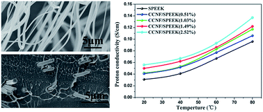
An easy spinning-based strategy was developed to fabricate polyacrylonitrile nanofibers as a precursor to obtaining continuous carbon nanofiber (CCNF) mats after carbonization. The composite membrane was then prepared by incorporating CCNFs into sulfonated poly(ether ether ketone) (SPEEK) for application in proton-exchange membrane fuel cells. Scanning electron microscopy, X-ray diffraction, thermogravimetric analysis, and tensile strength tests were used to characterize plain SPEEK and composite membranes. All dense composite membranes were found to have excellent water swelling, high mechanical performance, good proton conductivity, and low methanol permeability. The composite membrane with 0.51 wt% CCNFs displayed a proton conductivity of 0.041 S cm−1 at room temperature and was fully hydrated. Moreover, the relative selectivity of the hybrid membrane with 2.52 wt% CCNFs was 1.5 times higher than that of a pure SPEEK membrane. These results showed that the CCNF-supported SPEEK membranes were promising polyelectrolyte membranes for fuel cell applications.

1. Introduction

Proton-exchange membrane (PEM) fuel cells (PEMFCs) are attracting considerable attention because of their high energy density and efficiency, low emissions, and various applications such as in residential power generation, portable electronics, and electric vehicles.1–4 The PEM is an important factor which affects the performance of PEMFCs because it acts as a proton conductor and a fuel separator between the anode and cathode.5,6 Currently, Nafion-based perfluorinated ionomer polymers are widely used as PEM because of their excellent mechanical, chemical, thermal stability and high proton conductivity. However, a few drawbacks associated with high cost, high methanol permeability, and low proton conductivity at high temperature have drawn great attention to the development of new electrolyte polymers to substitute for Nafion.

Accordingly, various PEMs have been studied to replace Nafion. Among the potential PEMs reported to date, sulfonated poly(ether ether ketone) (SPEEK) is attracting considerable attention because of its low cost and excellent mechanical and chemical properties.7 However, SPEEK also has some drawbacks in its practical application because membrane properties depend too strongly on the degree of sulfonation (DS). The SPEEK membrane in highly sulfonated DS (above 70%) accommodates too much water, which allows them to swell in aqueous solutions and even soluble in aqueous methanol solutions. Thus, low dimensional stability led to poor PEMs performance and could not be used as PEM.

However, the low DS (below 50%) of SPEEK membranes shows very low conductivity. For practical use, PEM must possess excellent mechanical properties and high proton conductivity simultaneously. Thus, the proton conductivity of SPEEK membrane at relatively low DS (with outstanding mechanical properties by nature) should be improved. For this purpose, several inorganic materials such as zirconium phosphate, tungstosilicic acid, imidazoles, and tungstophosphoric, have been applied.8–13 Recently, carbon-based materials ranging from activated carbons (ACs) to carbon nanotubes (CNTs) are used as fillers in PEMs to improve their mechanical property, thermal stability, and proton conductivity.14–16 In past studies, carbon-based materials are considered to be good electronic conductors. However, the effect of such materials on proton conductivity has not been thoroughly investigated. Based on semi-empirical quantum mechanical calculations, Zaporotskova et al. discussed proton conduction by relay and hopping mechanism along CNTs.17

Nevertheless, the properties of CNT composites mostly depend on the chosen polymeric matrix and the processing used to make the composites. Dispersing carbon nanotubes well in a matrix and forming good interfaces with polymer chains are difficult because of their smooth surfaces and agglomeration.18,19 Compared with particles, continuous carbon nanofibers (CCNFs) can be used without these concerns; moreover, CCNF mats could be easily blended with polymer matrix and uniformly located in an electrolyte polymer membrane. This kind of fiber-supported composite membrane is expected to possess excellent physical properties and performance.20–23

The solution blowing process provides a simple and versatile method for fabricating the precursor polymers of continuous carbon nanofibers. In the process, polymer solution streams are pressurized out then rapidly attenuated into fibers using a high-speed gas flow. Without considering the electric field interference as in electrospinning, using a die assembly containing a serial of orifices is possible. Using a die assembly possesses several advantages such as convenient operation and mass productivity. The solution blowing process has been recently used with several natural and synthesized polymers to produce ultrafine polymer fibers in the range of a few hundred nanometers in diameter.24–28

In the present work, solution blowing was used as a new strategy to produce CCNFs and a new class of polyelectrolyte membranes based on SPEEK filled with nanofibrous webs that have been prepared and evaluated for suitability in PEMFCs. A polyacrylonitrile (PAN) nanofiber mat was initially fabricated through the solution blowing process. Then, CCNFs were obtained through followed stabilization and carbonization treatment. Subsequently, the CCNFs mats were infused into the SPEEK solution to form pore-filled membranes. CCNFs impregnation further improves proton conductivity, proton stability, and the water retention properties of the SPEEK membrane. This process offers a promising strategy on the rational design of high-performance PEMs.

2. Experimental

2.1 Fabrication of CCNFs mats

A novel solution blowing apparatus with multi-nozzles that nanofibers could be produced in quantity, as reported in our previous work, is illustrated in Fig. 1.24,25 A special homebuilt die was used, which is similar to a commercial dual slot meltblown die. The die has 20 orifices in a row that is 5 mm apart center to center. The spinning solutions were prepared by dissolving 9 wt% polyacrylonitrile (PAN; Mw = 150[thin space (1/6-em)]000, Sigma Aldrich) in N,N-dimethylformamide (DMF; Sigma Aldrich). The solutions were then spinning at the gas pressure of 0.06 MPa with a feed rate of 200 mL h−1. Then, PAN nanofiber mats were collected on a nylon net placed at a distance of 1 m from the spinning nozzle. Subsequently, the PAN nanofiber mat was stabilized in air at 260 °C for 2 h and carbonized at 1000 °C for 1 h under nitrogen. During stabilization, the fibrous mat was drafted with a constant force (0.14 MPa) under a heating rate at 3 °C min−1, which increased to 5 °C min−1 during carbonization.
image file: c4ra06976e-f1.tif
Fig. 1 Schematic of the solution blowing apparatus.

2.2 Sulfonation of PEEK

The PEEK (grade 381G) was purchased from Victrex. PEEK was suflonated as follows. PEEK (28.0 g) was dissolved in 200 mL of 98% sulfuric acid under vigorous stirring at ambient temperature for 3 h and then at 45 °C for 8 h. After the sulfonation reaction was completed, SPEEK was washed with deionized water several times and dried in a vacuum oven for storage. The degree of sulfonation (DS) was determined using a back-titration method. The amount of 0.1 g of SPEEK particles was placed in 20 mL of 0.05 M NaOH aqueous solution. After 3 days, the solution was titrated with 0.05 M HCl aqueous solution. The sulfonation (DS) degree of SPEEK was determined through titration. Moreover, the calculation of DS has been reported elsewhere.29 SPEEK with a DS of 61% was used to prepare a composite membrane for further PEMFC test in this study.

2.3 Preparation of CCNF-supported SPEEK membrane

The composite membranes containing CCNFs were prepared using a solvent-cast method. The SPEEK solution (15 wt%) was poured to the CCNFs. In addition, the membranes were dried in a vacuum oven at 60 °C 6 h to remove the solvents and annealed at 100 °C for 12 h to form a good pore-filled CCNF/SPEEK membrane. The composite membrane was acidified using a 1 M H2SO4 solution and finally washed with deionized water. Then, the membrane was stored in deionized water at an ambient temperature before characterization. Membranes were fabricated with CCNFs mass fractions that ranged from 0.51% to 2.5%. The thickness of the membranes is exhibited in Table 1.
Table 1 Membrane thickness, methanol permeability, and relative selectivity of membranes at room temperature
Samples Membrane thickness (cm) Methanol permeability (10−7 cm2 s−1) Relative selectivity (104 S s cm−3)
SPEEK 0.0050 6.1 5.08
CCNF/SPEEK (0.51%) 0.0061 6.4 6.41
CCNF/SPEEK (1.03%) 0.0067 6.5 6.46
CCNF/SPEEK (1.49%) 0.0075 6.7 7.46
CCNF/SPEEK (2.52%) 0.0083 7.1 7.89


2.4 Characterization

For the evaluation of nanofibers and membranes morphology, the specimens were gold coated using a sputter coater and then scanned by a scanning electron microscope (SEM) (S-4800, Hitachi Co., Japan). X-ray diffraction measurements were performed on using X-ray (XRD) diffraction spectroscopy (D8 Discover with GADDS, BRUKER AXS Co., USA). All the measurements were performed at room temperature at an angular 2θ between 10° and 80° with a Ni-filtered Cu Kα1 radiation (λ = 1.542 Å) at 45 kV and 40 mA. FT-IR spectra of the membranes in ATR mode were recorded in the frequency range 4000–600 cm−1 on an Alpha T-Bruker instrument. Thermogravimetric analyses were performed using TGA instruments (STA409PC, Netzsch Co., Germany) under a dry nitrogen atmosphere at a heating rate of 10 °C min−1 from 30 °C to 800 °C. The composition of CCNFs was examined with an energy dispersive X-ray (EDX) microanalysis system which attached to a HITACHI H-7650 transmission electron microscope (TEM) by putting the sample on a copper grids.

The tensile strength of the composite membranes were measured with an Instron universal testing machine (3369, USA). The membranes were prepared with dimensions of 20 mm × 70 mm. The distance between the two grips of Instron was approximately 40 mm, and the tensile speed of the grips is set at 50 mm min−1.

The water uptake (WU) and swelling ratio (SR) of the membranes were determined by measuring the weight and dimensional differences between the fully hydrated and dried membranes. The WU and SR of the membranes were calculated from:

 
image file: c4ra06976e-t1.tif(1)
 
SR = (SwSd)/Sd (2)
where Ww and Wd are the weights of wet and dry membranes; and Sw and Sd are the water swollen membrane area and dry membrane area, respectively.

The proton conductivity of the samples was measured using the two electrodes.30 All of the membrane samples were in their protonated state, and the condition of measurement was 100% humidified. The proton conductivity, σ, was calculated from the impedance data, using the relationship:

 
image file: c4ra06976e-t2.tif(3)
where l, t, and w are the length, thickness, and width of the membrane, respectively. R is derived from the low intercept of the high frequency semicircle on a complex impedance plane with the real axis.

The methanol permeability was measured in an isothermal bath at 25 °C using a two-chamber diffusion cell method with a 10 M methanol solution. A detailed procedure was reported previously.7 The concentration of the methanol in the water cell was determined by using a HP6890N gas chromatograph. Methanol permeability was calculated from:

 
image file: c4ra06976e-t3.tif(4)
where CB(t), D, K, C, t0, VB, A, and L are methanol concentration in cell B, methanol diffusion coefficient, methanol solubility, methanol concentration in cell A, time lag, diffusion reservoir volume, membrane area, and membrane thickness, respectively. Methanol permeability (P) values can be found according to P = DK.

3. Results and discussions

3.1 Morphology of CCNFs and CCNF/SPEEK membranes

Fig. 2a and b show the SEM images of PAN and CCNF nanofibers. Image analysis of nanofibers in each sample demonstrated that the average diameter was 334 ± 157 nm for PAN nanofibers and 250 ± 54 nm for CCNFs. In other words, the carbonization of nanofibers led to a considerable decrease in nanofiber diameter and narrower diameter distribution. Considerable decrease in nanofiber diameter gives CCNFs a larger specific surface area, which is a key advantage for composite fabrication because the higher specific surface area leads to a better interface between matrix and disperse. Moreover, under the constant drafting force during the stabilization process, the CCNFs have shown high orientation degree.
image file: c4ra06976e-f2.tif
Fig. 2 SEM images of (a) as-spun PAN nanofibers, (b) carbon nanofibers, (c) cross-sectional and (d) surface of CCNF/SPEEK membrane with CCNFs content of 1.03%.

Fig. 2c and d show images of the surface and cross-section of a composite membrane CCNF/SPEEK with a CCNFs mass fraction of 1.03%. Fig. 2c shows that the CCNFs were totally immersed into a SPEEK phase and dispersed loosely in the matrix. The nanfibers are dispersed well in the through-thickness direction, rather than gathered as a thin layer because CCNFs were continuous fibers and accumulated as nonwoven mats that could maintain their shape during the impregnation process.31 No significant crack was observed, which indicates the good compatibility between the carbonaceous nanofibers and the SPEEK phase mainly due to the small diameter of CCNFs. Notably, the voids observed in the SEM picture is due to the nanofiber tearing apart when the membrane was cut so that the transversal section can be observed. Thus, no porosity remains during the membrane preparation. Finally, Fig. 2d shows a surface image of the composite membrane. The membrane was totally compact, i.e., no porosity could be observed.

3.2 Structure and properties of CCNF/SPEEK

SPEEK and CCNF-supported SPEEK membranes were investigated using XRD (Fig. 3). The XRD pattern of composite membranes showed peaks at 21°, which belong to SPEEK, and the peaks at 26°, which belong to CCNFs.32 Obviously, XRD patterns confirmed the presence of CCNFs within SPEEK matrix. In addition, all the composite membranes occurred a peak at 23°. Also, the relative strength of the peak of 23° increases with the content of CCNFs increasing. The phenomenon could be presumed as the redistribution of CCNFs in the SPEEK membrane and form a fusion peak of SPEEK and CCNFs because of the stronger interaction between CCNFs and SPEEK matrix.
image file: c4ra06976e-f3.tif
Fig. 3 XRD patterns of SPEEK and composite membranes with different CCNFs content.

The interaction between CNF and SPEEK matrix was confirmed by FT-IR analysis. As shown in Fig. 4, the spectrum of SPEEK shows characteristic peaks at 1024.25 cm−1 assigned to the stretching vibrations of S[double bond, length as m-dash]O group, and 1078.65 and 1218.69 cm−1 to the symmetric and asymmetric stretching vibrations of O[double bond, length as m-dash]S[double bond, length as m-dash]O group, respectively. While the peaks shifted to 1025.30, 1081.07 and 1220.97 cm−1 respectively for the membrane of CCNF/SPEEK with 2.25% CCNFs content.33,34 And other peaks (708.56 cm−1 for S–O group and 1645.31 cm−1 for –Ar–C([double bond, length as m-dash]O)–Ar– group) also shifted.35


image file: c4ra06976e-f4.tif
Fig. 4 FT-IR spectra of (a) SPEEK and (b) the composite membrane with 2.52% content of CCNFs.

TGA curves of pristine and composite SPEEK membranes are shown in Fig. 5. The figure shows the onset of desulfonation at 350 °C and the backbone degradation of SPEEK at around 500 °C for all membrane systems. The char yield of CCNF/SPEEK was higher than the pure SPEEK, which mainly originated from the addition of CCNFs. According to EDX analysis, the composition of CCNF include C, O and Cu, and their content are 93.59%, 3.02% and 3.21% in atomic percentage, respectively. Here, the existence of Cu was due to the copper grid which the CCNF was put on. So the CCNF are almost C element and a small quantity of O which was introduced in the carbonization process. These TGA curves suggested that all the membranes are suitable for proton conducting materials in terms of thermal stability.


image file: c4ra06976e-f5.tif
Fig. 5 TGA curves of CCNF/SPEEK composite membranes with different CCNFs contents.

Fig. 6 shows the stress–strain curves of the test membranes obtained from the mechanical measurements. As shown, the mechanical properties of CCNF/SPEEK membranes were further improved by introducing CCNFs. The composite membranes exhibited much higher tensile strength and lower percentage elongation when the stretch reached a stable state as CCNF content increased from 0.51 wt% to 2.5 wt%, compared with pure SPEEK membrane. The reason is that CCNFs included into the polymer matrix behave like physical crosslinking points and restrict the movements of polymer chains.36 The interlocking between matrix and fibers reinforced the composite and restrict the movements of polymer chains.37–39


image file: c4ra06976e-f6.tif
Fig. 6 Stress–strain curves of SPEEK and composite membranes.

The water uptake is one of important parameters for PEM because water can not only facilitate the dissociation of the protons from –SO3H groups but also promotes the micro-phase separation for water-filled channel to transport protons. In the present study, all membranes have been studied at various temperatures from 20 °C to 80 °C. At an immersion temperature of 20 °C, the WU of the pristine SPEEK 61 was 32% and it monotonically increased with CCNF content to 36%, 38%, 41%, and 44% for the 0.51 wt%, 1.03 wt%, 1.49 wt%, and 2.5 wt% composite, respectively (Fig. 7a). Ghasemi et al. and Hou et al. reported similar conclusions in their study.40,41


image file: c4ra06976e-f7.tif
Fig. 7 Water uptake (a) and swelling ratio (b) of different membranes at varying temperature.

Although the WU increased, the SR of composite membranes was in controllable range. The temperature increased, and the swelling ratio of CCNF/SPEEK (1.03%) increased from 29.5% to 32.3%. The swelling ratio of SPEEK increased from 26.5% to 34.1% (Fig. 7b). The introduced CCNF led to a slight increase in SR value with increased temperature. The composite membranes exhibited relatively stable swelling due to the non-expandable nature of CCNF. Moreover, the introduced CCNFs were continuous and intertwined as nonwoven mats that could restrain the swelling of the membranes.24

The increasing WU in the hybrid membrane synergistically enhanced charge transport because sufficient hydronium ions can now propagate the aqueous phases. Fig. 8 shows the dependence of the conductivity at varying temperatures. At 20 °C, the conductivity of the pure SPEEK membrane was 0.031 S cm−1. The conductivity increased from 0.041 S cm−1 to 0.056 S cm−1 as CCNF content increased. Fig. 8 shows that the conductivities of the pure SPEEK membrane was below those of the CCNF/SPEEK membranes, which is related with the lower WU found in the former membrane. Compared with pure SPEEK, the ion-exchange capability of CCNF also enhanced the proton conduction properties of composite membrane. Moreover, the fiber morphology of continuous carbonaceous nanofibers can enhance proton conduction characteristics. Hasani-Sadrabadi also showed that the ionomeric nanofibers can be carried out to promote proton conductivity.42 Moreover, the conductivity of the membranes increased when the temperature was from 20 °C to 80 °C, which indicates that proton conduction is a thermally activated process.


image file: c4ra06976e-f8.tif
Fig. 8 Proton conductivity of different membranes at varying temperature.

Above all, the composite membranes had high proton conductivity. Membranes used for PEMFCs must have high proton conductivity and possess an effective barrier function to stop methanol crossover from anode to cathode. Fig. 9 shows that the methanol permeability of composite membrane was low and exhibited slight modification compared with the pure SPEEK membrane. This phenomenon could be attributed to the strong interfacial interactions between SPEEK and the CCNFs nonwoven mats with a large surface area (described in Section 3.1), which restrained the methanol permeation as we expected.


image file: c4ra06976e-f9.tif
Fig. 9 Methanol permeability and relative selectivity of the membranes.

With high proton conductivity of composite membranes, the slight modification of methanol permeability was not affecting the selectivity (the ratio of the proton conductivity to the methanol permeability).43 The selectivity was commonly used as a guideline for the evaluation of the comprehensive performance of membrane.

Fig. 9 shows that the higher selectivity of the composite membranes was obtained, and the relative selectivity of the composite membranes increased as CCNF content increased.

4. Conclusions

A novel type of CCNF/SPEEK hybrid membrane was developed by incorporating a network of CNF mat into SPEEK. With the assistance of continuous CCNFs, the obtained CCNF/SPEEK membranes were revealed to have a condensed and uniform structure, as well as good mechanical, thermal, and dimensional stabilities. CCNF incorporation improved the water uptake and proton conductivity of the SPEEK membranes. When the contents of CCNFs were well controlled, the composite membranes exhibited relatively low methanol permeability. Therefore, these CCNF/SPEEK membranes were promising materials for PEMFC applications.

Acknowledgements

The author would like to thank National Natural Science Foundation of China (51103104), Tianjin Natural Science Foundation (13JCZDJC32600) and Technology program of Tianjin Municipal Education Commission (20130324) for their financial support.

Notes and references

  1. X. Du, J. Yu, B. Yi, M. Han and K. Bi, Phys. Chem. Chem. Phys., 2001, 3, 3175–3179 RSC.
  2. C. Beauger, G. Laine, A. Burr, A. Taguet and B. Otazaghine, J. Membr. Sci., 2013, 430, 167–179 CrossRef CAS PubMed.
  3. N. Hasanabadi, S. R. Ghaffarian and M. M. Hasani-Sadrabadi, Solid State Ionics, 2013, 232, 58–67 CrossRef CAS PubMed.
  4. J. L. Lu, Q. H. Fang, S. L. Li and S. P. Jiang, J. Membr. Sci., 2013, 427, 101–107 CrossRef CAS PubMed.
  5. B. Annapurna, S. Meenakshi, S. D. Bhat and S. Seshadri, Chem. Eng. J., 2013, 231, 373–379 CrossRef CAS PubMed.
  6. Z. Liwei, C. So-Ryong, Z. Hendren, P. Jin-Soo and M. R. Wiesner, Chem. Eng. J., 2012, 204–206, 87–97 Search PubMed.
  7. J. Zhang and Z. Zhou, J. Power Sources, 2007, 31, 721–724 CAS.
  8. S. Sambandam and V. Ramani, J. Power Sources, 2007, 170, 259–267 CrossRef CAS PubMed.
  9. N. T. Q. Chi, D. X. Luu and D. Kim, Solid State Ionics, 2011, 187, 78–84 CrossRef PubMed.
  10. P. Staiti, Mater. Lett., 2001, 47, 241–246 CrossRef CAS.
  11. S. S. Madaeni, S. Amirinejad and M. Amirinejad, J. Membr. Sci., 2011, 380, 132–137 CrossRef CAS PubMed.
  12. W. Li, M. Waje, Z. Chen, P. Larsen and Y. Yan, Carbon, 2010, 48, 995–1003 CrossRef CAS PubMed.
  13. C. Wang, Z. X. Liu, Z. Q. Mao, J. M. Xu and K. Y. Ge, Chem. Eng. J., 2005, 112, 87–91 CrossRef CAS PubMed.
  14. J. Thomassin, J. Kollar, G. Caldarella, A. Germain and C. Detrembleur, J. Membr. Sci., 2007, 303, 252–257 CrossRef CAS PubMed.
  15. H. C. Chien, L. D. Tsai, A. Kelarakis, C. M. Lai, J. N. Lin, J. Fang, C. Y. Zhu and F. C. Chang, Polymer, 2012, 53, 4927–4930 CrossRef CAS PubMed.
  16. V. Ijeri, L. Cappelletto, S. Bianco, M. Tortello, P. Spinelli and E. Tresso, J. Membr. Sci., 2010, 363, 265–270 CrossRef CAS PubMed.
  17. I. V. Zaporotskova, N. G. Lebedev and P. A. Zaporotskov, Phys. Solid State, 2006, 48, 806–811 CrossRef CAS.
  18. W. Zhou, J. Xiao, Y. Chen, R. Zeng and S. Xiao, Polym. Adv. Technol., 2011, 22, 1747–1752 CrossRef CAS.
  19. Z. Chai, C. Wang, H. Zhang, C. M. Doherty and B. P. Ladewig, Adv. Funct. Mater., 2010, 20, 4394–4399 CrossRef CAS.
  20. W. Liu, S. Wang, M. Xiao, D. Han and Y. Meng, Chem. Commun., 2012, 48, 3415–3417 RSC.
  21. J. Won, H. Lee, J. Lim, J. Kim, Y. T. Hong and S. Lee, J. Membr. Sci., 2014, 450, 235–241 CrossRef CAS PubMed.
  22. J. B. Ballengee and P. N. Pintauro, J. Membr. Sci., 2013, 442, 187–195 CrossRef CAS PubMed.
  23. T. Tamura, R. Takemori and H. Kawakami, J. Power Sources, 2012, 217, 135–141 CrossRef CAS PubMed.
  24. B. Zhang, X. P. Zhuang, B. Cheng, N. Wang and Y. Ni, Mater. Lett., 2014, 115, 248–251 CrossRef CAS PubMed.
  25. X. P. Zhuang, L. Shi, K. F. Jia, B. W. Cheng and W. M. Kang, J. Membr. Sci., 2013, 429, 66–70 CrossRef CAS PubMed.
  26. X. P. Zhuang, X. C. Yang, L. Shi, B. W. Cheng and K. T. Guan, CarbohydPolym., 2012, 90, 982–987 CrossRef CAS PubMed.
  27. S. Sinha-Ray, Y. Zhang, A. L. Yarin, S. C. Davis and B. Pourdeyhimi, Biomacromolecules, 2011, 12, 2357–2363 CrossRef CAS PubMed.
  28. X. P. Zhuang, K. Jia, B. Cheng, X. Feng, S. Shi and B. Zhang, Chem. Eng. J., 2014, 237, 308–311 CrossRef CAS PubMed.
  29. Y. Heo, H. Im and J. Kim, J. Membr. Sci., 2013, 425, 11–22 CrossRef PubMed.
  30. S. Nam, S. Kim, Y. Kang, J. W. Lee and K. Lee, J. Membr. Sci., 2008, 322, 466–474 CrossRef CAS PubMed.
  31. T. Tamura and H. Kawakami, Nano Lett., 2010, 10, 1324–1328 CrossRef CAS PubMed.
  32. H. Hou, R. Polini, M. L. Di Vona, X. Liu and E. Sgreccia, Int. J. Hydrogen Energy, 2013, 38, 3346–3351 CrossRef CAS PubMed.
  33. S. Guhan and D. Sangeetha, Int. J. Polym. Mater., 2009, 58, 87–98 CrossRef CAS.
  34. S. M. Javaid Zaidi, Electrochim. Acta, 2005, 50, 4771–4777 CrossRef PubMed.
  35. B. Mecheri, A. DEpifanio, E. Traversa and S. Licoccia, J. Power Sources, 2008, 178, 554–560 CrossRef CAS PubMed.
  36. S. Kumar, T. Rath, R. N. Mahaling, C. S. Reddy, C. K. Das, K. N. Pandey, R. B. Srivastava and S. B. Yadaw, Mater. Sci. Eng., B, 2007, 141, 61–70 CrossRef CAS PubMed.
  37. K. Lozano and E. V. Barrera, J. Appl. Polym. Sci., 2000, 79, 125–133 CrossRef.
  38. M. C. Wiesenberger, E. A. Grulke, D. Jacques, T. Rantell and R. Andrews, J. Nanosci. Nanotechnol., 2003, 3, 535–539 CrossRef PubMed.
  39. J. Zeng, B. Saltysiak, W. S. Johnson, D. A. Schiraldi and S. Kumar, Composites, Part B, 2004, 35, 173–178 CrossRef.
  40. M. Ghasemi, S. Shahgaldi, M. Ismail, Z. Yaakob and W. R. W. Daud, Chem. Eng. J., 2012, 184, 82–89 CrossRef CAS PubMed.
  41. H. Hou, R. Polini, M. L. Di Vona, X. Liu, E. Sgreccia, J. Chailan and P. Knauth, Int. J. Hydrogen Energy, 2013, 38, 3346–3351 CrossRef CAS PubMed.
  42. I. Shabani, M. M. Hasani-Sadrabadi, V. Haddadi-Asl and M. Soleimani, J. Membr. Sci., 2011, 368, 233–240 CrossRef CAS PubMed.
  43. Y. Zhao, Z. Jiang, L. Xiao, T. Xu and H. Wu, J. Power Sources, 2011, 196, 6015–6021 CrossRef CAS PubMed.

This journal is © The Royal Society of Chemistry 2014