
Design and fabrication of surface-enhanced Raman scattering substrate from DNA–gold nanoparticles assembly with 2–3 nm interparticle gap†
Li Zhang*a,
Hongwei Mab and
Liangbao Yangc
aSchool of Biological and Chemical Engineering, Anhui Key Laboratory of Spin Electron and Nanomaterials, Suzhou University, Suzhou 234000, PR China. E-mail: zhlisuzh@163.com
bSchool of Life Science, Anhui University, Hefei 230039, PR China
cInstitute of Intelligent Machines, Chinese Academy of Sciences, Hefei 230031, China
First published on 2nd September 2014
Abstract
An ideal substrate for surface-enhanced Raman scattering (SERS) detection should induce a high signal enhancement and be easy to synthesize. Here, we showed that gold nanoparticles (Au NPs) were self-assembled onto DNA strands by electrostatic interactions and formed a well-defined DNA–Au hybrid structure with an interparticle gap of ca. 2–3 nm between two adjacent Au NPs, which could be used as active SERS substrates. Four different types of molecule, i.e. Rhodamine 6G, 4-aminothiophenol, pyridine and 2,4,6-trinitrotoluene, were studied on these substrates. All the detection limits for each analyte on the DNA–Au hybrid substrate were at least one order of magnitude higher than those on Au NPs alone without self-assembly on DNA. This phenomenon of assembly-induced signal enhancement has been experimentally and theoretically demonstrated in this study.
1. Introduction
The control of interparticle interactions and structures in nanoparticle assemblies using organic molecules or biomolecules as mediators has attracted increasing interest toward the design of functional nanostructures.1–4 In particular, the design and fabrication of these functional nanostructures have been widely explored for signal amplification in the field of surface-enhanced Raman scattering (SERS).5 For conventional SERS substrates, the interstitial size is difficult to control due to the stochastic distribution of the nanoparticles (NPs). Both the experimental and theoretical results indicated that the precise control of the gaps among the nanostructures in the range of sub-10 nm was critical for the preparation of SERS substrates with high enhancement factors, especially the 1–3 nm range for optimal coupling of the electromagnetic field.6–9 Some efforts10,11 have demonstrated the significant potential of SERS as a sensitive tool for molecular sensing; however, the precise control of the gaps in the sub-10 nm range on a SERS-active substrate for intense SERS enhancement is still a great challenge based on the state-of-the-art technology.Biomolecular structures are attractive as templates to form nanoscale architectures because of their size, geometry and ability to interact with inorganic materials.12 The DNA molecule is a kind of attractive biological template for constructing nanostructures with a specific shape and unique properties. DNA is a rigid biopolymer that can withstand a range of pH and temperature. In particular, DNA possesses a linear structure, large aspect ratio (length/diameter), well-defined sequences, and a variety of superhelix structures. The negatively charged phosphate groups of DNA have a strong affinity to bind metal cations and positively charged NPs.13 In addition to the linear structure, large-scale DNA networks can also be fabricated by controlling the concentration of DNA.14 A large-scale λ-DNA network on a mica surface was successfully fabricated through a self-assembly method.15 Recently, we reported a sunlight-induced formation of silver–gold bimetallic nanostructures on a DNA template for highly active SERS substrates and application in TNT/tumor marker detection,16 and we also studied the DNA–Ag hybrid structure for ultratrace mercury analysis.17
To date, the synthesis of SERS substrates with a gap of ca. 2–3 nm in solution controlling the uniform distribution of hot spots and the uniformity of SERS nanostructures are still challenging.18–22 Here, a very simple and practical strategy was experimentally and theoretically demonstrated for high-yield synthesis of a new kind of nanostructure with a well-defined 2–3 nm interparticle gap between two adjacent Au NPs by the self-assembly of Au NPs on DNA (Fig. 1). The anchored DNA strands in these particles facilitated the formation of nanogaps. This kind of nanogap between the Au NPs surfaces resulted in the amplification of the SERS signal intensity.
 | ||
| Fig. 1 DNA-mediated fabrication and characterization of DNA–Au hybrids. (A and B): TEM of the positively charged Au NPs and using DNA-modified Au NPs to form DNA–Au hybrids, respectively. The inset is a high-resolution TEM image. (C): UV-vis spectra for the solution of: DNA (curve 1), positively charged Au NPs (curve 2) and DNA–Au hybrids (curve 3). Inset: gradual change in the color of the solution. (D): Percentage of the gap distances of Au NPs on DNA template. A section analysis reveals the gap of the particles is about 2–3 nm. | ||
2. Experimental section
2.1 Materials and chemicals
300 ng μL−1 λ-DNA was purchased from Fermentas Life Sciences Ltd. Company (Shenzhen, China) and was extensively dialyzed in pure aqueous solution. All chemicals used in this study were of analytical grade. HAuCl4·3H2O was obtained from Shanghai Chemical Co. Ltd., China. All the solutions were prepared in double-distilled water.2.2 Characterizations
Ultraviolet-visible (UV-vis) absorption spectra were collected on a SolidSpec-3700 spectrophotometer. The transmission electron microscopy (TEM) images were obtained with a JEOL JEM-2010 instrument operated at 100 kV. SERS measurements were carried out on a LabRam I confocal microprobe Raman system (JY, France). The excitation wavelength is 532 nm. All the spectra reported were the results of a single 2 s accumulation time. AFM measurements were performed with a digital Nanoscope IIIa multimode system (DI, Santa Barbara, CA). The image was acquired in the tapping mode. The AFM measurements were performed in air at room temperature with a Si cantilever. The force constant of the cantilever was 0.1–0.6 N m−1 with the scan rate at 1–2 Hz.2.3 Preparation of DNA–Au hybrids
Positively charged Au NPs with diameters of about 6 nm were prepared by the phase transfer approach following the procedure of Gittins et al.23 The fabrication of the network nanostructure was carried out as in our former study.16 An aqueous solution of positively charged Au NPs was added to a solution of λ-DNA (20 mL, 300 ng μL−1, the diluted DNA solution is about 50 ng μL−1) and the solution was mixed thoroughly and kept for 3 h at room temperature. The DNA solution changed to wine-red, indicating the formation of DNA–Au hybrids. The precipitate, i.e. the synthesized DNA–Au hybrid, was resuspended, centrifuged with distilled water three times and then ultrasonically dispersed into distilled water.2.4 SERS measurements on the DNA–Au network films
1 mL of the as-prepared DNA–Au NPs hybrid solution was centrifuged at 8000 rpm for 10 min. The supernatant was discarded, and the pellet was redispersed to 10 mL. 10 μL of the as-prepared DNA–Au hybrid was dropped onto the surface of a silicon wafer and dried in air as the SERS substrate. The dried DNA–Au network film had a diameter of ca. 2 mm. 1 mL of the positively charged Au NPs solution was centrifuged at 16![[thin space (1/6-em)]](https://www.rsc.org/images/entities/char_2009.gif) 000 rpm for 30 min and the pellet was redispersed to 10 mL. The following steps are similar to the above. Using Rhodamine 6G (R6G) stock solutions of 10−3 M, we prepared solutions with concentrations down to 10−6 M via successive dilutions by a factor of 10. After immersing the SERS substrates into the corresponding solution for some time in order to ensure that adsorption equilibrium was reached, the substrates were then taken out and rinsed with deionized water. The samples were dried in air. In order to avoid the catalytic and photochemical decomposition caused by laser exposure, the laser power at the sample position was 0.5 mW, the laser beam was focused on the sample in a size of about 2 μm and the typical accumulation time used for the study was 2 s. For every sample, we took three SERS spectra at different positions of the substrate and then averaged them. Similarly, a series of concentrations of 4-aminothiophenol (4-ATP), pyridine (Py) and 2,4,6-trinitrotoluene (TNT) were prepared. The conditions of their SERS measurements are similar to those in the protocol of R6G SERS detection.
000 rpm for 30 min and the pellet was redispersed to 10 mL. The following steps are similar to the above. Using Rhodamine 6G (R6G) stock solutions of 10−3 M, we prepared solutions with concentrations down to 10−6 M via successive dilutions by a factor of 10. After immersing the SERS substrates into the corresponding solution for some time in order to ensure that adsorption equilibrium was reached, the substrates were then taken out and rinsed with deionized water. The samples were dried in air. In order to avoid the catalytic and photochemical decomposition caused by laser exposure, the laser power at the sample position was 0.5 mW, the laser beam was focused on the sample in a size of about 2 μm and the typical accumulation time used for the study was 2 s. For every sample, we took three SERS spectra at different positions of the substrate and then averaged them. Similarly, a series of concentrations of 4-aminothiophenol (4-ATP), pyridine (Py) and 2,4,6-trinitrotoluene (TNT) were prepared. The conditions of their SERS measurements are similar to those in the protocol of R6G SERS detection.
3. Results and discussion
3.1 DNA-based fabrication of DNA–Au hybrids
This study provides a one-step strategy for preparing DNA–Au hybrids as SERS-active substrates by simple mixing of DNA and Au colloids. Our strategy for the self-assembly of Au NPs on a DNA template can be summarized as follows: firstly, positively charged Au NPs were synthesized through a phase transfer method,23 which gave a diameter of ca. 6 nm as observed by TEM (Fig. 1A); secondly, the as-synthesized Au colloids were mixed with the λ-DNA aqueous solution to obtain the highest density of self-assembly of DNA–Au hybrids (Fig. 1B); thirdly, the Au NPs were self-assembled onto the DNA strands by electrostatic interactions between the negatively charged phosphate backbones of DNA and positively charged Au NPs; finally, a DNA network provides a good template for the formation of compact and uniform nanostructures by the electrostatic assembly of Au NPs on DNA strands. In a typical experiment, because the negatively charged phosphate groups as the backbone of a DNA molecule have a linear shape with periodic arrangement and have a strong affinity to the positively charged Au NPs, the DNA strands can be used as a template with a highly accurate position-controlling capability which finally resulted in the self-assembly of DNA–Au hybrids with a 2–3 nm interior gap (Fig. 1B). Importantly, the HRTEM images (inset in Fig. 1B) verified that Au touched the DNA surface in some parts to form a DNA–Au chain. The final hybrids were successfully fabricated in a high yield of ca. 95% and all particles had a uniform nanogap as shown in the TEM images in Fig. 1B. The average gap size, measured from the TEM images, was determined to be 2–3 nm (Fig. 1D). The synthesized DNA–Au nanostructures were highly stable in solution over three months in ambient conditions. All these characteristics were very important for SERS detection. As shown in Fig. 1C, the DNA absorption peak appeared at 256 nm (curve 1). Compared with curve 1 in Fig. 1C, the maximum intensity of the DNA–Au hybrid absorption peak in curve 3 was red-shifted to 277 nm. Because of the intimate nature of the DNA–Au complex, this effect could be attributed to changes in the duplex structure,16 and therefore the new peak at 277 nm is attributed to the interaction between the groups of DNA and the surface atoms of positively charged Au NPs.23 In curve 2, the peak at 509 nm can be attributed to the surface plasmon resonance of small Au NPs. From curve 3, the plasmon resonance peak was red-shifted to 526 nm with a broader shape, owing to the complete DNA–Au hybrid formation, but the extinction intensity had increased compared with the Au NPs. The color of the particle solution deepened as shown in the inset of Fig. 1C.Fig. 2 shows typical TEM images of self-assembled DNA–Au nanostructures obtained by adsorbing Au NPs onto the DNA networks with different volume ratios ranging from 4:1 to 1:1, respectively. There were some single Au NPs in the solutions as shown in Fig. 2A and B. It was clearly visible from the TEM images in Fig. 2C and D that almost every chain was decorated with a high density of Au NPs. The measured distance of the particles attached to the DNA chains was in the range 2 to 3 nm, which fell into the size range of the Au NPs we used for the assembly of the SERS substrate. The result showed that the optimal volume ratio was about 2:1 to 1:1. It is necessary to point out that, if the colloid concentration was too low, it was difficult to adsorb sufficient NPs on the DNA chains. However, if the colloid concentration is too high, large dissociative NPs will form rapidly when the NPs are injected into the DNA solution.24 In this study, 300 ng μL−1 λ-DNA containing 48502 base pairs was extensively dialyzed in pure aqueous solution. In each sample, the final concentration of λ-DNA was 50 ng μL−1. Based on this calculation, 26 DNA bases per nanoparticle is the optimum ratio. To further identify the particles assembled on the DNA chains, Au NPs with different diameters (such as 15 nm and 25 nm) were also chosen for the assembly. The results showed that only some DNA chains were decorated by many particles, and the nanogaps between the Au NPs were not uniform (details are shown in ESI†, Fig. S1), which further verified that the size of the NPs was the key factor for the successful assembly in our strategy. It was obvious that the interactions between DNA and NPs were predominant. By using this specific characteristic of DNA and Au NPs, we have fabricated Au NPs-decorated DNA nanowires or nanochains. Without question, many factors will affect the electrostatic assembly of Au NPs on DNA strands. In this work, the main purpose is to provide a simple and efficient strategy for the preparation of SERS substrates. The strategy we have developed in this work does not require any chemical modifications (e.g. introducing special chemical groups) to the DNA chains for the assembly. Therefore, it minimizes any possible changes in the native properties of DNA, which is very important for SERS.
 | ||
| Fig. 2 Typical TEM images of the mixtures of Au NPs and DNA solution with different volume ratios: (A) 4:1, (B) 3:1, (C) 2:1 and (D) 1:1 (Au NPs:DNA). [DNA] = 50 ng μL−1. | ||
Fig. 3A shows the UV-vis spectra recorded from a mixture of 50 ng μL−1 DNA and different concentrations of Au NPs. Prior to mixing, it can be seen that there was an identical peak at about 509 nm with increasing concentration from line 1 to line 3, whereas an absorption peak was observed at around 526 nm after mixing; the absorption peak at 509 nm was red-shifted toward longer wavelengths in the presence of a DNA template and there was no other peak observed. UV-vis spectra of DNA-templated NPs self-assembled with different DNA concentrations are also shown in Fig. 3B. The absorption peaks were still red-shifted toward longer wavelengths, from 509 nm to 526 nm, in the presence of a DNA template with increasing concentrations and there was no other peak observed, which was not similar to the literature.25 The established theoretical descriptions of Mie scattering from similar small aggregate clusters suggested that the plasmon resonance absorption of the aggregates would have an additional long-wavelength component in the optical absorption spectrum relative to the absorption from isolated NPs dispersed in solutions.26 The first peak, located near the resonance peak of monodispersed particles, was attributed to the quadrupole plasmon excitation in coupled NPs, the other peak at a longer wavelength was attributed to the dipole plasmon resonance of the NPs aggregate.27
 | ||
| Fig. 3 (A) UV-vis spectra of Au NPs (dashed line) and DNA–Au (solid line) with different volume ratios of Au NPs and DNA, [DNA] = 50 ng μL−1, volume ratios of lines 1, 2 and 3 corresponding to 4:1, 3:1, 2:1, respectively. (B) UV-vis spectra recorded for an aqueous mixture of DNA–Au complex with increasing DNA concentration from 50 ng μL−1 to 100 ng μL−1. | ||
However, in our study, the new absorbance peaks at 526 nm did not shift further to much longer wavelengths with increasing gold concentration. We attributed this phenomenon to the NPs self-assemblies in a linear shape, rather than their aggregations. On the other hand, there was no longitudinal absorbance mode. That is to say, the assembled Au NPs were discontiguous, which was in agreement with the TEM observations.
Optical waveguide (OWG) spectroscopy is a new and powerful technique for surface monitoring. The technique takes advantage of the evanescent field, which penetrates less than a wavelength beyond the waveguide surface, to selectively respond to the adsorption of immobilized chemical or biological molecules over a given spectral bandwidth. Here, λ-DNA is stretched, aligned, and immobilized on an optical waveguide glass surface by the molecular combing method.28 By adding Au colloids onto the DNA-modified glass surface, we used OWG spectroscopy to monitor the Au NPs dynamic assembly process through the electrostatic interactions between the negatively charged phosphate backbone and positively charged Au NPs. Through OWG absorption spectroscopy, the time of adsorption equilibrium was determined, and the Au NPs adsorption process at the solid–liquid interface followed diffusion control theory. Fig. 4A shows the single-layer assembly of Au NPs, resulting in the appearance of an absorbance peak centered at ca. 527 nm, which could be attributed to the located surface plasmon resonance (LSPR) peak of the adsorbed Au NPs. Even if we prolonged the reaction time, there was no red shift of this LSPR or appearance of new peaks at longer wavelengths which could be attributed to coupling, multilayer assembling, or aggregation of Au NPs on the OWG surface.29 At the same time, the intensity of the absorbance does not increase, which is in agreement with the result of Fig. 3; this means that electrostatic interactions are the key factor during the process.
 | ||
| Fig. 4 (A) Assembly process of single-layer Au NPs on DNA-modified OWG surface. (B) Tapping-mode AFM images of self-assembled films of DNA–Au obtained by adsorbing Au NPs onto DNA, [DNA] = 50 ng μL−1. | ||
As reported in previous articles, the height of double-stranded DNA spread on mica was about 0.4–0.7 nm measured by AFM in tapping mode. When the DNA concentration is 50 ng μL−1, the DNA strands can form a single-chain or net-like structure. A section analysis indicated that the strand height was about 2 nm (data not shown). Fig. 4B shows typical AFM images of DNA–Au networks with 50 ng μL−1 DNA. The image clearly confirmed that Au NPs were adsorbed onto the DNA strands with high specificity. It was also found that the assembled Au NPs were denser along the DNA strands. The height of the DNA–Au networks was in the range 7.8 nm to 15.5 nm. These results indicated that two or more DNA strands overlapped each other at a concentration of 50 ng μL−1;15 another reasonable explanation may be that two Au NPs were anchored to the same location of the DNA strands. It should be noted that the dimensions of the particles were measured according to the height rather than the width, because the AFM tip radius would affect the measurement.
3.2 Scheme of the fabrication of the gold-decorated DNA template and DDA simulation of optical electric field distribution
On the basis of the TEM and AFM results above, it was believed that the formation of the DNA–Au hybrid structures mainly resulted from the directing effect provided by the reactions between gold and Au NPs, and Au NPs and DNA. The maximum amount of Au NPs tethered to the DNA template was determined by the space-charge repulsion of positively charged Au NPs and by electrostatic interactions between the negatively charged phosphate backbone of DNA and the positively charged Au NPs. Our earlier study found that λ-DNA can form a cross-chain structure and a single-chain structure.16 In this study, a similar phenomenon was observed. According to the experimental results above, a possible formation mechanism of the DNA–Au hybrid structure was proposed as shown schematically in Fig. 5, including the cross-chain (A) and chain (B) modes of the DNA–Au complex. In our model, we supposed that the Au NPs were aligned to the plane of the phosphate DNA backbone. Our reason is that the phosphodiester backbone has a linear shape with negative charge compensated by the counterion Au NPs. The negative charge repulsion is by no means completely screened by the counter charge, since the Debye screening length is about 1.8 nm, because the solution conditions used here lead to distances significantly larger than the distance between two adjacent phosphate groups (max. 0.76 nm).30 On the other hand, positive charge repulsion of Au NPs also exists. In our experiments, we found that the distance between Au NPs along the DNA template is about 2–3 nm. | ||
| Fig. 5 Proposed self-assembly structures of DNA–Au (A) cross-chain structure, (B) chain structure. | ||
In order to understand the mechanism and to calculate the field enhancement, a theoretical simulation was carried out using the DDA method. The extinction spectra of the Au NPs alone, the Au NPs assembled on a cross-chain DNA template, and the Au NPs assembled on a chain DNA template with a gap of 3 nm were calculated using the DDA method in Fig. 6. The corresponding SPR peaks were at 517 nm (curve 1), 523 nm (curve 2) and 527 nm (curve 3). We noticed that the SPR peak at 527 nm was just located at the wavelength of the excitation line of 532 nm and was more suitable in the present study. Then we calculated the local electric field distribution of the Au NPs without or with DNA templates. Fig. 7A–C show the local electric field distribution of the Au NPs alone, the Au NPs assembled on a cross-chain DNA template, and the Au NPs assembled on a chain DNA template, respectively. The calculated results revealed that the magnitude of the maximum electric field enhancement is about 6 times for single Au NPs, about 7 times for Au NPs with a cross-chain structure, and about 8 times for Au NPs with a chain structure. The highest enhancement of Raman scattering appeared at the surface and the junction, with magnitudes of about 1296-, 2401- and 4096-fold, respectively. It should be pointed out that a great deal of chain-like gold nanostructures existed, i.e. the assembly of DNA–Au hybrids had a high yield (see Fig. 1B and 2). As this structure increased, the number of “hot junctions” increased, and thus a more intense SERS band was produced. As the NPs became very close with controllable gaps, the LSPR can be excited in the well-controlled nanogap. Hence, it produced a large electromagnetic field enhancement and a tremendous increase in the Raman intensity for molecules located in the gap between the particles, and thus allowed the detection of monolayer-adsorbed species on a practically important substrate of general interest. Thus, we considered the gap effect to be the dominant factor for the field enhancement.
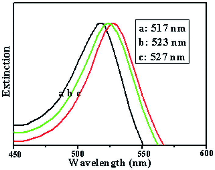 | ||
| Fig. 6 Calculated extinction efficiencies of Au NPs. Curve a: single particles, curve b: on cross-chain DNA, curve c: on chain DNA. The nanospheres have a diameter of 6 nm. | ||
 | ||
| Fig. 7 DDA simulation of the field enhancement of gold NPs. (A) single, (B) on cross-chain DNA, (C) on chain DNA, respectively. The wavelengths are chosen as their own resonant wavelengths (517 nm, 523 nm, and 527 nm, respectively). | ||
3.3 SERS studies of DNA–Au substrate
Several types of typical analyte were selected as models to demonstrate the performance of this substrate in SERS because they are important and have been well characterized by SERS.Fig. 8A shows the intensity of SERS spectra of R6G with different concentrations from 1.0 × 10⁻⁵ to 1.0 × 10⁻⁶ M. The spectral features of R6G molecules were present: the peak at 1189 cm−1 is associated with C–C stretching vibrations, and the peaks at 1311, 1359, 1507, 1571 and 1644 cm−1 are associated with aromatic C–C stretching vibrations. The Raman bands at about 1644, 1507, 1359, 1189, 770, and 611 cm−1 can be attributed to R6G and agreed well with the literature data.31,32 Comparing curve 1 with curve 3, the Raman peak strongly decreased in intensity as the concentration of R6G decreased, and was clearly observable at a concentration as low as 1.0 × 10⁻⁶ M on the DNA–Au substrate. This indicates that DNA–Au as a SERS substrate provides strong Raman signals of R6G. Comparing curve 2 with curve 3, we believe that this specific SERS substrate is more reasonable than a Au substrate with the same size.
 | ||
| Fig. 8 Typical SERS spectra of different concentrations of analyte molecules on different SERS substrates. (A) R6G, curve 1: DNA–Au substrate, 10−5 M, curve 2: Au substrate, 10−5 M, curve 3: DNA–Au substrate, 10−6 M. (B) 4-ATP, curve 1: Au substrate, 10−5 M, curve 2: DNA–Au substrate, 10−6 M, curve 3: DNA–Au substrate, 10−5 M. (C) Py, curve 1: Au substrate, 10−5 M, curve 2: DNA–Au substrate, 10−7 M, curve 3: DNA–Au substrate, 10−6 M. (D) TNT, curve 1: Au substrate, 10−4 M, curve 2: DNA–Au substrate, 10−5 M, curve 3: DNA–Au substrate, 10−4 M. | ||
Fig. 8B presents the SERS spectra of 4-ATP on the substrates formed by the Au NPs alone and the DNA–Au hybrid, respectively. A strong band can be observed at ca. 1075 cm−1, which was assigned to the C (benzene ring)–S stretching vibration, while the corresponding band located at 1570 cm−1 was assigned to the C–C stretching vibration of the benzene ring. The band at 1005 cm−1 originated from the C–C bending vibration, and the bands at 1185 cm−1 and 1469 cm−1 originated from the C–H bending vibration and a combination of the C–C stretching and C–H bending vibrations, respectively. Moreover, the bands located at 1139 cm−1 and 1429 cm−1, which were ascribed to charge transfer from the metal to the adsorbed molecules, could also be seen clearly, and this suggested a perpendicular orientation of the 4-ATP unit to the metal surface.33 From curve 1, curve 2 and curve 3 of Fig. 8B, we could see that curve 3 and curve 2 had the better spectral quality with more peaks and higher signal intensities, while curve 1 had relatively weaker signals and some peaks had disappeared. Comparing curve 1 with curve 2, the detection limit of 4-ATP by SERS on a DNA–Au substrate is at least one order of magnitude higher than that on Au NPs alone in the same conditions.
Fig. 8C presents the SERS spectra of Py. The spectra had strong Py bands at ca. 652, 995, 1033, 1216 and 1582 cm−1. These spectra agreed very well with those reported in previous works.34 These five bands are assigned to totally symmetric vibrational modes, indicating that Py adsorption made the aromatic ring normal to the surface. From curve 1, curve 2 and curve 3 of Fig. 8C, it could be noted that the signal of Py was about one order of magnitude higher on the DNA–Au substrate than that on Au NPs alone.
To demonstrate that sensitive detection with the DNA–Au substrates was widely applicable, we further measured the Raman spectra of TNT. The detection and identification of trace TNT is a problem of great practical interest. The peak at 1609 cm−1 was due to the C![[double bond, length as m-dash]](https://www.rsc.org/images/entities/char_e001.gif) C aromatic stretching vibration. The strong Raman band at 1359 cm−1 was due to the NO2 symmetric stretching vibration, the weak band at 1532 cm−1 was due to the NO2 asymmetric stretching vibration, and the band at 1210 cm−1 was due to the C6H2–C vibration. Out-of-plane vibrations can be seen at 792 and 822 cm−1 at a modest intensity. All of these were due to TNT vibration.35–37 Fig. 8D demonstrates that a DNA–Au substrate can detect in concentration ranges down to 10−5 M TNT.
C aromatic stretching vibration. The strong Raman band at 1359 cm−1 was due to the NO2 symmetric stretching vibration, the weak band at 1532 cm−1 was due to the NO2 asymmetric stretching vibration, and the band at 1210 cm−1 was due to the C6H2–C vibration. Out-of-plane vibrations can be seen at 792 and 822 cm−1 at a modest intensity. All of these were due to TNT vibration.35–37 Fig. 8D demonstrates that a DNA–Au substrate can detect in concentration ranges down to 10−5 M TNT.
4. Conclusions
In summary, a one-step strategy for preparing DNA–Au hybrids as SERS-active substrates by the simple mixing of DNA and Au colloids was demonstrated. The Au NPs were self-assembled onto the DNA strands by electrostatic interactions between the negatively charged phosphate DNA backbone and positively charged Au NPs. The DNA network provided a better template for the formation of compact and uniform nanostructures by the electrostatic assembly of Au NPs on DNA strands with a well-defined 2–3 nm nanogap in high yields. The SERS measurements of small-molecule probes, such as R6G, 4-ATP, Py and TNT, were performed on these DNA–Au hybrid substrates with significantly enhanced sensitivity and reproducibility compared to the Au NPs alone. The large Raman enhancements achieved on these new substrates are believed to be the result of the formation of nanogap structures.Acknowledgements
This work is supported by the National Science Foundation of China (no. 20871089, 21271136), the Important Project of Anhui Provincial Education Department (KJ2010ZD09) and the Program of Innovative Research Team of Suzhou University (2013kytd02).Notes and references
- P. K. Sudeep, B. I. Ipe, K. G. Thomas, M. V. George, S. Barazzouk, S. Hotchandani and P. V. Kamat, Nano Lett., 2002, 2, 29 CrossRef CAS.
- L. Wang, X. Shi, N. N. Kariuki, M. Schadt, G. R. Wang, Q. Rendeng, J. Choi, J. Luo, S. Lu and C. J. Zhong, J. Am. Chem. Soc., 2007, 129, 2161 CrossRef CAS PubMed.
- G. R. Wang, L. Wang, Q. Rendeng, J. Wang, J. Luo and C. J. Zhong, J. Mater. Chem., 2007, 17, 457 RSC.
- R. Kaminker, M. Lahav, L. Motiei, M. Vartanian, R. Popovitz-Biro, M. A. Iron and M. E. van der Boom, Angew. Chem., Int. Ed., 2010, 49, 1218 CrossRef CAS PubMed.
- Y. C. Cao, R. Jin and C. A. Mirkin, Science, 2002, 297, 1536 CrossRef CAS PubMed.
- Y. Lu, G. L. Liu and L. P. Lee, Nano Lett., 2005, 5, 5 CrossRef CAS PubMed.
- Y. Fang, N. H. Seong and D. D. Dlott, Science, 2008, 321, 388 CrossRef CAS PubMed.
- X. B. Xu, K. Kim, H. F. Li and D. L. Fan, Adv. Mater., 2012, 24, 5457 CrossRef CAS PubMed.
- D. K. Lim, K. S. Jeon, J. H. Hwang, H. Kim, S. Kwon, Y. D. Suh and J. M. Nam, Nat. Nanotechnol., 2011, 6, 452 CrossRef CAS PubMed.
- M. Pilo-Pais, A. Watson, S. Demers, T. H. LaBean and G. Finkelstein, Nano Lett., 2014, 14, 2099 CrossRef CAS PubMed.
- Q. M. Yu, P. Guan, D. Qin, G. Golden and P. M. Wallace, Nano Lett., 2008, 8, 1923 CrossRef CAS PubMed.
- Y. Q. Wen, C. K. McLaughlin, P. K. Lo, H. Yang and H. F. Sleiman, Bioconjugate Chem., 2010, 21, 1413 CrossRef CAS PubMed.
- L. L. Sun, D. X. Zhao, Z. Z. Zhang, B. H. Li and D. Z. Shen, J. Mater. Chem., 2011, 21, 9674 RSC.
- A. G. Wu, Z. Li, H. L. Zhou, J. P. Zheng and E. K. Wang, Analyst, 2002, 127, 585 RSC.
- G. Wei, H. L. Zhou, Z. G. Liu, Y. H. Song, L. L. Sun, T. Yang and Z. Li, J. Phys. Chem. B, 2005, 109, 23941 CrossRef CAS PubMed.
- L. B. Yang, G. Y. Chen, J. Wang, T. T. Wang, M. Q. Li and J. H. Liu, J. Mater. Chem., 2009, 19, 6849 RSC.
- H. L. Liu, L. B. Yang, H. W. Ma, Z. M. Qi and J. H. Liu, Chem. Commun., 2011, 47, 9360 RSC.
- W. Kubo and S. Fujikawa, Nano Lett., 2011, 11, 8 CrossRef CAS PubMed.
- T. Jesse, P. Pavaskar, P. M. Echternach, R. E. Muller and S. B. Cronin, Nano Lett., 2010, 10, 2749 CrossRef PubMed.
- L. D. Qin, S. L. Zou, C. Xue, A. Atkinson, G. C. Schatz and C. A. Mirkin, Proc. Natl. Acad. Sci., 2006, 103, 13300 CrossRef CAS PubMed.
- X. M. Qian, X. H. Peng, D. O. Ansari, Q. Yin-Goen, G. Z. Chen, D. M. Shin, L. Yang, A. N. Young, M. D. Wang and S. M. Nie, Nat. Biotechnol., 2008, 26, 83 CrossRef CAS PubMed.
- C. L. Zavaletaa, B. R. Smitha, I. Waltonb, W. Doeringb, G. Davisb, B. Shojaeib, M. J. Natanb and S. S. Gambhir, Proc. Natl. Acad. Sci., 2009, 106, 13511 CrossRef PubMed.
- D. I. Gittins and F. Caruso, Angew. Chem., Int. Ed., 2001, 40, 3001 CrossRef CAS.
- Y. J. Sun, G. Wei, Y. H. Song, L. Wang, L. L. Sun, C. L. Guo, T. Yang and Z. Li, Nanotechnology, 2008, 19, 115604 CrossRef PubMed.
- B. F. Pan, D. X. Cui, C. Ozkan, P. Xu, T. Huang, Q. Li, H. Chen, F. T. Liu, F. Gao and R. He, J. Phys. Chem. C, 2007, 111, 12572 CAS.
- P. Galletto, P. F. Brevet and H. H. Girault, J. Phys. Chem. B, 1999, 103, 8706 CrossRef CAS.
- S. Basu, S. K. Ghosh, S. Kundu, S. Panigrahi, S. Praharaj, S. Pande, S. Jana and T. Pal, J. Colloid Interface Sci., 2007, 313, 724 CrossRef CAS PubMed.
- H. Nakao, H. Hayashi, T. Yoshino, S. Sugiyama, K. Otobe and T. Ohtani, Nano Lett., 2002, 2, 475 CrossRef CAS.
- J. N. Anker, W. P. Hall, O. Lyandres, N. C. Shah, J. Zhao and R. P. Van Duyne, Nat. Mater., 2008, 7, 442 CrossRef CAS PubMed.
- F. M. Liu, P. A. Kollensperger, M. Green, A. E. G. Cass and L. F. Cohen, Chem. Phys. Lett., 2006, 430, 173 CrossRef CAS PubMed.
- X. H. Li, G. Y. Chen, L. B. Yang, Z. Jin and J. H. Liu, Adv. Funct. Mater., 2010, 20, 2815 CrossRef CAS.
- L. B. Yang, H. L. Liu, Y. M. Ma and J. H. Liu, Analyst, 2012, 137, 1547 RSC.
- L. S. Jiao, Z. J. Wang, L. Niu, J. Shen, T. Y. You, S. J. Dong and A. Ivaska, J. Solid State Electrochem., 2006, 10, 886 CrossRef CAS.
- G. F. S. Andrade and M. L. A. Temperini, J. Raman Spectrosc., 2009, 40, 1989 CrossRef CAS.
- M. W. Shao, L. Lu, H. Wang, S. Wang, M. L. Zhang, D. Ma and S. T. Lee, Chem. Commun., 2008, 2310 RSC.
- Y. H. Sun, K. Liu, J. Miao, Z. Y. Wang, B. Z. Tian, L. N. Zhang, Q. Q. Li, S. S. Fan and K. L. Jiang, Nano Lett., 2010, 10, 1747 CrossRef CAS PubMed.
- L. B. Yang, L. Ma, G. Y. Chen, J. H. Liu and Z. Q. Tian, Chem.–Eur. J., 2010, 16, 12683 CrossRef CAS PubMed.
Footnote |
| † Electronic supplementary information (ESI) available. See DOI: 10.1039/c4ra06947a |
| This journal is © The Royal Society of Chemistry 2014 |