Xiaoyu Weia,
Jie Liu*a,
Yawen Wanga,
Yusheng Lia,
Yan Gea,
Jiajun Chena,
Hui Yaoa,
Jinping Huanga,
Xibin Yu*a and
Ming Zhan*b
aThe Education Ministry Key Lab of Resource Chemistry and Shanghai Key Laboratory of Rare Earth Functional Materials, Department of Chemistry, Shanghai Normal University, Shanghai 200234, People's Republic of China. E-mail: liujie@shnu.edu.cn; xibinyu@shnu.edu.cn
bPhysics and Chemistry Test Lab, Shanghai Pudong New Area Center for Disease Control & Prevention, Shanghai 200136, People's Republic of China. E-mail: mzhan@pdcdc.sh.cn
First published on 24th September 2014
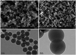
Highly luminescent and photostable dye-h-silica (dye-hybrid-silica) nanoparticles (NPs) were prepared using a base-catalyzed reverse microemulsion method. We obtained dye-h-silica nanoparticles with ∼65 nm radius, a narrow particle size distribution, high fluorescence intensity, and a controlled internal architecture. The luminescence intensity of the dye-h-SiO2 is 2.4 times higher than that of the pure dye in aqueous solution. The incorporation of dye molecules into the silica NPs protects the dye from the surrounding environment, as the silica layer is a good shield against oxygen and moisture, so that the dye-h-silica monoliths (SMs) maintain their initial luminescence after the encapsulation curing process. Green and red light-emitting dye-h-SMs are successfully applied to the preparation of remote trigger LEDs.
Different to the dye-h-silica mentioned above, a traditional dye-silica composite with moderate emission efficiency was prepared using phenyltriethoxysilane (PTES) which can produce both hydrophobic and hydrophilic sites inside the silica matrix.5 Thereby, organic dye could be found inside the silica matrix by adjusting the amount of PTES. A high quantity of PTES was found to make the particles hydrophobic and caused difficulties in the surface modification by dispersion, and the particles formed using this approach have a broad size distribution. There are some problems when using the Stöber process, for example, (1) the diameters of the SiO2 nanoparticles are nonuniform, (2) the SiO2 nanoparticles showed severely reduced photoluminescence (PL), (3) serious dye leakage occurs in aqueous solution.
A reverse microemulsion method, taking place between the water and the oil phase, has been applied to prepare dye-h-silica. Several encapsulating methods have been reported for nanoparticles.6–13 In the following, we present in detail methods for preparing homogeneously doped dye-h-SMs, while retaining the original PL efficiency, and show their application for LEDs. Currently, remote-phosphor LEDs are receiving a great deal of attention and their commercialization is expanding to high-volume applications, including general lighting and displays. Especially, compared to traditional white LEDs, remote-phosphor LEDs have many advantages in terms of high efficiency and a high-temperature environment with a more stable color point system. However, remote-phosphor LEDs need to be more cost-effective and more color-uniform. At present, there are several combinations for remote trigger LEDs.
The mixed light from a blue InGaN LED with a yellow phosphor (cerium-doped yttrium aluminum garnet: YGA) makes a cool remote-phosphor LEDs.14 This is the most efficient and economical structure found so far, while the pale white light from the blue and yellow hues cannot express the natural colors of an object faithfully in general circumstances. However, until now, few red phosphors can be excited by low energy wavelengths (blue light), and RG dye-h-silicas display a much enhanced luminescence intensity.
To obtain stable dyes, packaging with polymers and inorganic shells such as silica is generally employed to avoid a direct contact between the dye and its surroundings. However, the large-scale preparation of such core–shell nanomaterials in a cost-effective way is yet to be investigated. Therefore, we developed a one-pot strategy for the scalable fabrication of silica-hybridized dyes in aqueous solution. The structure of the dye-h-SiO2 is not an exact core–shell structure with single dye molecules being solely in the middle of silica as previously reported,15 but in the form of a hybrid in which the dyes are embedded in the silica. The ultrafine dye-h-SiO2 can be readily obtained on a sub-kilogram-scale in one batch, and the dyes have been shown to be highly stable in the silica resin, encouraging the industrial application of dyes. Hence, we chose this kind of dye-h-SiO2 as the critical raw material for the fabrication of dye–polymer composites.
Fig. 1(a1) and (a2) show the scanning electron microscopy (SEM) images of the Ru(bpy)-h-SiO2 nanoparticles. The average diameter of the dye-h-SiO2 nanoparticles is 65 ± 3 nm. The functionalized NPs were dispersed very well in aqueous solution, and no aggregation was observed due to the electrostatic repulsion force between the NPs. (The analysis results of the FITC-h-SiO2 nanoparticles are similar to those of the Ru(bpy)-h-SiO2 nanoparticles.) The dye-h-SiO2 nanoparticles are so small that they could avoid sedimentation and phase separation. Silica particles with a large size may cause phase segregation at the interface of SiO2 and the polymer matrix. The internal pore structure of the NPs could be observed using transmission electron microscopy (TEM, Fig. 1(b1) and (b2)). Many disordered holes could be found in the SiO2 NPs and the dye molecules are dwelling in these holes steadily. Upon introduction of the dye to the silica NPs, it has been found that the dyes maintain their luminescence efficiency or even exceed those of the pure dyes, and the stability of the dyes has improved significantly. As we all know, it is difficult to maintain the initial optical properties of pure dyes during the device fabrication and long-term operation, while the silica layer is a good shield against oxygen and moisture so that the dye-h-SMs could maintain their initial luminescence after high-power UV irradiation and the 150 °C LED encapsulation curing process.
![]() | ||
Fig. 1 Scanning electron microscopy images of Ru(bpy)32+-doped silica nanoparticles (a1, a2). Transmission electron micrographs of Ru(bpy)32+-doped silica nanoparticles (b1, b2). |
The fluorescence of dye-h-SiO2 NPs was compared with that of the corresponding pure dye molecules (Fig. 2). By matching the absorption of the free dyes and the particle solutions, we determined the intensity ratios of the luminescence emission of Ru(bpy)32+ and FITC in our silica particles versus the free dyes in aqueous solution to be 2.4 and 1.6, respectively. In other words, the luminescence intensities of the nanoparticles are 2.4 or 1.6 times higher than those of the pure dyes, and the nanoparticles do not undergo photobleaching as the pure dyes do over a long period of continuous intense light exposure. The encapsulation in silica can improve the luminescence intensity because of an increase in quantum efficiency of the dyes.16,17 The emission maximum of the nanoparticles shifts by 10 nm towards longer wavelengths compared with the pure Ru(bpy)32+ dye due to aggregation of the dye molecules inside the nanoparticles.18 For the Ru(bpy)-doped nanoparticles, this results in a redshift with the emission at 614 nm while that of the pure Ru(bpy)32+ dye is at 604 nm. For the FITC-doped nanoparticles, there also exists a redshift with the emission being at 528 nm while that of the pure FITC dye is at 522 nm. These superior properties suggest that the dye-h-SiO2 nanoparticles are excellent fluorescent powders for LEDs.
![]() | ||
Fig. 2 Panels (a) and (b) display the fluorescence spectra of the free dye molecules and the dye-h-SiO2 nanoparticles. |
Ru(bpy)32+ is well-known to be a good oxygen-sensing reagent, because the luminescence of the dye can be quenched by oxygen. Oxygen exercises a great influence on the emission intensity of the dye in the solid state.19 Recently, Santra and co-workers have reported that the dyes are well-protected inside the silica network in normal atmosphere.18 There was no evident change in the emission intensity for the dye-h-SiO2 NPs when the air pressure was increased from 1 to 8 psi. Only when the pressure was further increased could a decrease in emission intensity be observed. There are two possibilities for this photobleaching in the solid state. The first one is that a minute amount of oxygen penetrates into the silica network, and the second one is that some of the dye remains close to the surface of the silica particles, because the surface area/volume ratio of those dye composites is quite high. In both cases, external silica coating on the dye surface will be a reasonable shield to minimize photobleaching of the dyes and there was no photobleaching observed over a long period of intensive laser excitation. This observation, therefore, suggests that external silica coating completely isolates the dyes from the outside environment, thereby preventing any oxygen molecule penetration. In conclusion, the dyes have been passivated by the novel multi-layered structure and the passivated dyes show a high luminescence intensity and improved stability in solid-state devices.
Fig. 3(a) shows the PL spectra of the dye-h-SMs with different concentrations after the thermal treatment using an excitation at 460 nm. The luminescence emission intensity of the dye-h-SMs with 0.016 to 0.047 wt% doping content has been enhanced with the increased addition of the dye molecule. However, the luminescence emission intensity decreased with a further increase in dye content (0.094 wt%). The dye-h-SMs are highly transparent, and the transparency comes to more than 86% from the visible to the infrared region, as show in Fig. 3(b). The inset displays that the transparency of the dye-h-SMs decreases with increasing dye-h-SiO2 doping content, but the dye-h-SMs still maintain high transparency in the visible range. The decrease in transmittance of the dye-h-SMs for the 0.094 wt% doping content, compared to the 0.016 to 0.047 wt% dye contents, would reduce the luminescence emission intensity of the dye-h-SMs. The increase in luminescence emission intensity due to the increase in doping content is not enough to compensate the decrease in transmittance, which leads to the observed overall decrease of the luminescence emission intensity, as showed in Fig. 3(a). It can be observed from Fig. 3(c) that the dye-h-SMs exhibit a high visible light transparency and Fig. 3(d) depicts the visual effect of the samples under irradiation with a handheld broadband 365 nm UV lamp, from left to right the doping dyes are Ru(bpy)32+ and FITC. There are two reasons for the high transparency of the dye-h-SMs. The first one is that the presence of silanol groups on the silica surface makes the silica nanoparticles hydrophilic, thus the dye-h-silica NPs could basically homogenously disperse in the epoxy matrix,12 so it is easy to disperse them into epoxy resin. The second one is that the small cell of the SiO2 NPs benefits the refraction of the dye.
Green and red light-emitting dye-h-SMs containing different dye concentrations were prepared and applied to blue LEDs. The dye-h-SMs were molded as a disk with a diameter of 4 mm and placed on the LED chip, followed by silicone encapsulation, as shown in Fig. 4(a). The blue LED and the dye-LED were operated using a 60 mA current at 3.3 V and both spectra are shown in Fig. 4. Traditionally, the phosphor glue was dropped on the LED chip and packaged by the transparent epoxy resin. The heat dissipation is very bad, and the working temperature is as high as 250 °C. By placing the phosphor layer far from the chip, heat would escape from the device rather than being trapped where it would cause excessive yellowing of the epoxy encapsulant, and then the lifetime of the LEDs could be significantly improved.20 When doing a comparison between remote phosphor and traditional white LEDs, it can be shown that the new technology enables the thin remote phosphor sheet to be separated from the LED chip. The good heat dissipation can lower the phosphor’s operating temperature and improve both efficiency and longevity.
To achieve efficient dye-LEDs, therefore, it is essential to prepare high-quality dye-h-SiO2 NPs with a high luminescence intensity, to protect the dyes against fluorescence quenching caused by high temperatures.
The color coordinates of the green spectrum, red spectrum and the commercial blue LED (460 nm) emission spectrum are marked at (0.2866, 0.6402), (0.6194, 0.3795) and (0.14, 0.12) in the CIE 1931 color space (Fig. 5). sRGB is a standard RGB color space created cooperatively by HP and Microsoft in 1996 to be used on monitors, printers and the Internet. The color coordinates of the sRGB color triangle are (xR, yR) = (0.64, 0.33), (xG, yG) = (0.30, 0.60), (xB, yB) = (0.15, 0.06), as shown in Fig. 5.21 The result indicates that an adjustable white light and highly color-saturated remote-phosphor LED could be realized by adjusting the ratio of the green and the red dye.
![]() | ||
Fig. 5 Color coordinates of the dye-LED (red spot and green spot) and the sRGB-LED (white line) on the CIE 1931 color space. |
This journal is © The Royal Society of Chemistry 2014 |