Facile synthesis of nanostructured carbon nanotube/iron oxide hybrids for lithium-ion battery anodes

Seung-Ho Yu abc, Xiaohui Guod, Daishun Lingab, Dong Young Chungab, Aihua Jinab, Mohammadreza Shokouhimehrab, Taeghwan Hyeon*ab and Yung-Eun Sung*ab
aCenter for Nanoparticle Research, Institute for Basic Science (IBS), Seoul 151-742, Republic of Korea. E-mail: thyeon@snu.ac.kr; ysung@snu.ac.kr
bSchool of Chemical and Biological Engineering, Seoul National University, Seoul 151-742, Republic of Korea
cResearch Institute of Advanced Materials (RIAM), Seoul National University, Seoul 151-742, Republic of Korea
dKey Lab of Synthetic and Natural Functional Molecule Chemistry of Ministry of Education, The College of Chemistry & Materials Science, Northwest University of China, Xi'an 710069, P. R. China

Received 19th June 2014 , Accepted 11th August 2014

First published on 13th August 2014


Abstract

Nanostructured carbon nanotubes/iron oxide hybrids (CNIOHs) were synthesized by a scalable Bake-Break-Mix process which involves three simple steps. Porous rod-like iron oxide arrays were first synthesized via the decomposition of iron(II) oxalate dihydrate at 300 °C for 5 h. The prepared rod-like structures were simply a well-organized alignment of numerous iron oxide nanoparticles. Breaking these rod-shaped iron oxide arrays into well-dispersed nanoparticles was accomplished by ultrasonication. Finally, single-wall carbon nanotubes were added to the suspension during sonication which allowed the dispersed iron oxide nanoparticles to adsorb to the surface resulting in the nanostructured CNIOHs. CNIOHs were employed as anode materials and showed excellent capacity, cyclic stability and rate capability.

1. Introduction

Lithium-ion batteries (LIBs) have received much attention as an emerging class of rechargeable battery device owing to their higher energy density, greater efficiency and longer cycle life compared to their alternatives in the past decades.1–3 More recently, market demands for lower-cost electrode materials, higher specific energy densities and better cycling performances for LIBs have fuelled an increase in research devoted to developing new materials with improved performance.4–6 Recently, various nanostructured materials have been extensively investigated as potential anode electrodes as these materials tend to provide a higher energy density and longer cycling features; thus the focus here is on simplifying these materials to lower production costs.4 Among the available anode materials, nano-sized transition metal oxides such as Fe3O4, Fe2O3, MoO3 and Co3O4 present viable options as they are capable of extracting/inserting excess Li+ and provide significantly larger reversible capacities than commercial anode graphite electrodes.7–10 In contrast to the intercalation mechanism on graphite electrodes, transition metal oxides are reduced to small metal clusters when oxygen reacts with Li+ to form Li2O. This generally causes volume expansion and structural destruction simultaneous with electrochemical cycling.1,4 To overcome this issue, several optimization methods have been examined including nanoparticle (NP) shape and size control and coating the particles with conductive additives resulting in enhanced reversible capacity and rate capability of the metal oxide electrodes in LIBs. Some of the most promising anode candidate materials contain forms of iron oxide such as hematite (α-Fe2O3) and magnetite (Fe3O4). These oxides possess a higher theoretical capacity (∼1000 mA h g−1) than that of graphite electrodes. Additionally, non-toxic hematite particles are easily fabricated by cost-effective and environmentally-friendly processes.11,12 While iron oxide nanomaterials have been extensively studied as potential anode electrodes for LIBs, they still suffer from poor cyclability and rapid capacity fading due to their low intrinsic electronic conductivity and structure destruction during the charge–discharge process.13 The addition of a conductive carbon coating on the iron oxide nanostructures has been one of the most successful strategies to overcome the low conductivity issue,14–22 it also may provide a protective shield against the destructive mechanical stresses caused by large volume change during the charge–discharge processes.16,20 Thus the combination of these two materials may provide a synergistic effect leading to a hybrid material with optimal electrochemical performances.17

Meanwhile, much progress has been made in developing new carbon-coated iron oxide hybrids for lithium-ion anode materials in the past decades.13 Lou et al. successfully prepared MoS2/carbon nanotubes, Fe3O4/carbon composites, and carbon-coated Fe2O3 hierarchical nanostructures via hydrothermal growth and thermal transformation processes.17,23 When used in the anode of a battery, these composites demonstrated high capacities ∼800 mA h g−1 after 50 cycles at specific current densities. Piao et al. prepared carbon-coated magnetite nanocomposites24 and Ma et al. reported carbon-coated porous Fe2O3 composites as anode materials exhibiting a capacity of 900 mA h g−1 at 200 mA g−1 after 40 cycles.25,26 However, these methods require several time-consuming steps and hydrothermal reactions in autoclaves. Also an intricate multistep process for purifying materials from these complicated carbon coating fabrication processes is needed which hampers scalable syntheses.13,17,24

Highly conductive and flexible carbon nanotubes coated with iron oxide nanoparticles can circumvent these drawbacks and provide a three-dimensional electronic network to facilitate electron transfer.14 Moreover, uniform iron oxide nanoparticles grafted onto a single-wall carbon nanotube (SWCNT) backbone can further enhance the electrochemical activity and mechanical properties of the electrode due to their larger surface area and sufficient internal accessible space.27 SWCNT/metal oxide hybrids can be generally prepared via a facile thermal decomposition of metal precursor and followed by a physical binding process. Therefore, SWCNT/metal oxide hybrids could be very promising materials for large-scale synthesis making them economical from commercial point of view.28,29 Herein, we report on a facile, large-scale synthesis of nanostructured CNIOHs via the Bake-Break-Mix process. When prepared CNIOHs were employed as anode materials, they showed excellent capacity, cyclic stability and rate capability.

2. Experimental

2.1 Synthesis of carbon nanotubes and iron oxide hybrids

In a typical procedure, porous rod-like iron oxide arrays were prepared through thermal decomposition of 1 × 10⁻² M iron(II) oxalate dihydrate (FeC2O4·2H2O) at 300 °C and heating rate of 1 °C min−1 for 5 h in a tube furnace. The obtained iron oxide rod-like arrays were dispersed in 10 ml water and 2 ml HCl (2 M) and exposed to ultrasonic treatment for 3 h. Then, a mixture containing different weight percentage of commercial SWCNTs with 0.15 g CTAB and 35 ml H2O was prepared and added to the iron oxide NPs during the sonication process. The samples were exposed to ultrasound process for 5 more hours. Next the mixture was aged by shaking at a constant speed for 18 h at room temperature. Finally, the homogeneous mixture was centrifuged at 8000 rpm for 10 min to obtain CNIOH nanostructures. The isolated product was washed three times with DI water and ethanol and dried in oven at 60 °C. CNIOHs composites with variable loading level of 5.4, 11.3, and 14.9 wt%. SWCNT could be easily synthesized by varying the amount of SWCNT addition to the solution in ultrasound exposure step. Wherein, the prepared CNIOHs samples at different SWCNT loading levels of 5.4, 11.3, and 14.9 wt% can be denoted as CNIOHs-1, CNIOHs-2, and CNIOHs-3, respectively.

2.2 Characterization

X-ray diffraction (XRD) patterns were obtained using a Rigaku Dmax 2500 diffractometer. The morphologies of the samples were examined by high-resolution transmission electron microscopy (Tecnai F20 and JEOL-2010) and field-emission scanning electron microscope (SUPRA 55VP). The Brunauer–Emmett–Teller (BET) method was used to confirm the surface area and porosity of iron oxide via a Micromeritics ASAP-2000 nitrogen absorption analyzer. Thermal behavior of samples were performed by thermogravimetric analysis (Shimadzu DRG-60 and SDT-Q600). The Raman spectra were acquired using a Raman spectrometer (Jobin Yvon Co.) model HR800 employing a 10 mW helium/neon laser at 632.8 nm.

2.3 Electrochemical test

Working electrodes made of synthesized active materials powder, super P as a conducting agent and polyvinylidene fluoride as a binder (70[thin space (1/6-em)]:[thin space (1/6-em)]15[thin space (1/6-em)]:[thin space (1/6-em)]15 wt%) were mixed in n-methyl-2-pyrrolidinone solvent. The slurry was pasted onto a copper foil current collector via doctor blade method and pressed. Electrochemical test cells were assembled in an argon-filled glove box using coin-type half-cells (2016 type) with lithium foil as a counter electrode. LiPF6 (1.0 M) in ethylene carbonate and diethyl carbonate (1[thin space (1/6-em)]:[thin space (1/6-em)]1 vol%) was used as electrolyte. The cells were galvanostatically charged and discharged in the voltage ranged from 0.01 to 3.0 V vs. Li+/Li. All electrochemical measurements were made with a WBCS3000 cycler (WonA Tech, Korea) at room temperature. The specific capacity is calculated based on the total weight of composites (iron oxide and carbon nanotubes).

3. Results and discussion

Large-scale of nanostructured CNIOHs were synthesized via the Bake-Break-Mix process. The process involves first decomposing iron(II) oxalate dihydrate by “baking” at 300 °C for 5 h resulting in rod-shaped arrays of iron oxide NPs. We can then “break” the arrays to disperse the individual NPs by sonication. Once dispersed, SWCNTs are “mixed” into the suspension resulting in adsorption and the formation of nanostructured CNIOHs. The simplicity of this synthetic procedure allows the reproducible, large-scale production of CNIOHs. For example, 3.383 g of CNIOHs could be prepared from a single batch reaction (Fig. S1). When these CNIOHs were employed as anode materials, they exhibited a capacity around 1000 mA h g−1 at a current density of 200 mA g−1 which was well retained through 50 cycles. This was consistent for both 11.3 and 14.9 wt% SWCNT-loaded composites which are superior to previously reported carbon/iron oxide based anode materials.13,14,18,24

It is known that porous, column-shaped structures can be obtained via direct thermal decomposition of iron(II) oxalate precursor at high temperature ∼300 °C for 5 h. It is believed to occur in two steps; first, crystal water is released from the solid, then the FeC2O4 converts to iron oxide and carbon dioxide. Fig. 1b and c clearly show the synthesized iron oxide products are porous rod-like arrays. The TEM images show the obtained rods were well aligned in the same stacking directions (Fig. 1c and d). As shown in Fig. 1d, the length of the columns was measured to be above 10 μm. After thermal treatment of the iron(II) oxalate at 300 °C, rust-colored powder was obtained. The iron oxide sample was found to mainly contain α-Fe2O3 (hematite) as confirmed by XRD (Fig. 2). The hematite product contained a single crystalline feature and weak magnetite diffraction peaks.


image file: c4ra05945j-f1.tif
Fig. 1 (a) Schematic illustration of the formation of CNIOH nanostructures via Bake-Break-Mix process. (b) SEM image and (c and d) TEM images of porous rod-like iron oxide arrays sample obtained via thermal decomposition of the iron(II) oxalate dihydrate at 300 °C for 5 h with a heating rate 1 °C min−1.

image file: c4ra05945j-f2.tif
Fig. 2 XRD patterns of the different iron-based samples.

Thermogravimetry confirmed the proposed reaction mechanism. The first step of the thermal decomposition process occurs between 100 and 230 °C and involves the loss of water molecules (Fig. S2) as the anhydrous ferrous oxalate (FeC2O4) appears to be the dominant phase in this temperature range. FeC2O4 appears thermally stable up to about 230 °C at which point the second decomposition step can be observed. Within the calcinating temperature range of 230–300 °C the thermally induced conversion of FeC2O4 to iron oxide occurs yielding a total weight loss of 5.47 wt% during the whole thermal decomposition process.

Nitrogen adsorption–desorption isotherms were observed at 77 K to obtain the porous size of rod-like arrays (Fig. 3a). The nitrogen adsorption–desorption isotherms for porous rod-like iron oxide arrays show typical type-IV isotherms features suggesting uniform mesoporosity. The specific BET surface area and pore volume were ∼70 m2 g−1 and 0.21 cm3 g−1, respectively. According to the corresponding Barrett–Joyner–Halenda (BJH) pore size distributions calculated from the adsorption branches of the isotherms (Fig. 3b), the pore size distributions of the obtained sample are 4.3 and 37.4 nm, respectively. Moreover, it can be inferred that the porosity formation was mainly due to the release of CO2 from the bulk FeC2O4 structures and the structural rearrangement to iron oxide NPs.


image file: c4ra05945j-f3.tif
Fig. 3 (a) N2 adsorption–desorption isotherms and (b) corresponding pore-size distributions of porous rod-like iron oxide arrays.

The rod-like arrays are composed of numerous iron oxide NPs which result from the strong ultrasonic treatment process (Fig. S3). When dispersed, the iron oxide NPs can be bound to the SWCNT backbone by both electrostatic and van der Waals interactions and the resultant CNIOHs can be well dispersed in aqueous solution (Fig. 4). When the loading level of the SWCNTs was about 5.4 wt%, the synthesized iron oxide nanoparticles on the hybrid product were highly dispersed on the SWCNT backbones (Fig. 4a and d) and TEM images reveal the size of individual iron oxide NPs is below 50 nm. We also confirmed that SWCNTs were successfully embedded into the CNIOHs networks using Raman spectra (two Raman peaks centered at ∼1350 and 1600 cm−1) and TEM characterization (Fig. 5a). Interestingly, iron oxide NPs are first bound to the SWCNT backbone and then further aggregate to form denser cross-linking network hybrids (Fig. 4a). By loading more amounts of SWCNTs, highly packed CNIOHs network-like structures can be formed (Fig. 4b and e). Higher loading capacities of SWCNT components leads to compaction of the CNIOHs while keeping the individual iron oxide NPs well dispersed on the surface of SWCNTs backbones. Accordingly, when increase the SWCNTs content to ∼15 wt%, similar CNIOHs could be obtained (Fig. 4c and f).


image file: c4ra05945j-f4.tif
Fig. 4 TEM (a–c) and FE-SEM (d–f) images of the formed CNIOHs with different carbon nanotube loadings; (a and d): 5.4 wt%, (b and e): 11.3 wt%, (c and f): 14.9 wt%.

image file: c4ra05945j-f5.tif
Fig. 5 (a) Raman spectrum and (b) thermogravimetric analysis of CNIOHs.

Next, the electrochemical features of the prepared CNIOHs at different loading amounts of SWCNTs were performed. As shown in Fig. 6a–c, the charge–discharge voltage profiles can be obtained for three hybrid products with different SWCNT loading levels at a current density of 200 mA g−1. There are two plateaus around 1.65 and 0.84 V in the first discharge curve, which are typical of iron oxide, particularly hematite.30,31 These are related to the reduction with lithium ions to form Fe metal cluster embedded in a Li2O matrix. The poor kinetics of this conversion reaction is reflected as a large hysteresis in the voltage of the charge and discharge profiles. These slow kinetics of iron oxide can be enhanced by forming nanosized iron oxide particles and composites with carbonaceous materials.32,33 The first, second and third discharge (lithiation) capacities were found to be 1576.9, 1220.9 and 1222.2 for the 5.4 wt% sample, 1464.8, 1076.5 and 1073.4 mA h g−1 for the 11.3 wt% sample and 1474.2, 1047.9 and 1039.6 for the 14.9 wt%, respectively. Although the capacity of CNIOHs with 5.4 wt% SWCNT is the highest, the difference between the first and second cycle of that electrode is the lowest. The first irreversible capacity loss is attributed to the electrolyte decomposition and formation of a solid electrolyte interface (SEI) layer. The subsequent profiles are well overlapped, indicating that they are stable and show good reversibility.


image file: c4ra05945j-f6.tif
Fig. 6 The charge–discharge voltage profiles of CNIOHs with different carbon nanotube loadings for initial 5 cycles; (a): 5.4 wt%, (b): 11.3 wt%, (c): 14.9 wt%.

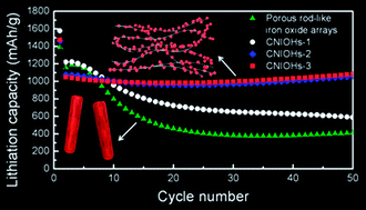
The cycle performances of CNIOHs with different SWCNT loadings are shown in Fig. 7a. As mentioned, the primary issue of the conversion reaction based materials for anode application is the dramatical volume change during cycling which results in cycling failure. The capacity of electrodes containing CNIOHs with 5.4 wt% iron oxide is above 1200 mA h g−1 for several initial cycles but decreases rapidly within 20 cycles. However, the capacity is gradually stabilized afterwards. It is worthwhile to note that the lithiation capacity after 80 cycles is 524 mA h g−1, which is still higher than that of commercially used graphite (372 mA h g−1). Both CNIOHs with 11.3 and 14.9 wt% exhibited excellent cyclic stability during 80 cycles and delivered high lithiation capacities of 1168 and 1179 mA h g−1 at 80th cycle, respectively. These values were higher than that of iron oxide or iron oxide/carbon nanotubes composites (Table S1).17,34–38 In order to further analyze the influence of SWCNT loadings, the rate performance testing was conducted for CNIOHs at varying current rate conditions (Fig. 7b). When we further increased the current density to 100 mA g−1 at the sixth charge–discharge cycle, the corresponding lithiation capacities for the 5.4, 11.3 and 14.9 wt% CNIOHs were obtained as 1162.2, 1071.7, and 1061.5 mA h g−1, respectively. After completing the 26th charge and discharge cycle, the applied current density was increased to 800 mA g−1 and the lithiation capacities for the 5.4, 11.3 and 14.9 wt% CNIOHs were 530.7, 760.5 and 811.5 mA h g−1, respectively. These results indicate the lithiation capacites at a current density of 800 mA g−1 are 38.4, 64.3, and 70.0% of those at a current density of 50 mA g−1 for the 5.4, 11.3 and 14.9 wt% CNIOHs, respectively. The conductive SWCNT network can enhance the electrochemical performances of the CNIOH electrodes by constructing an accessible three-dimensional electronic route for fast and stable charge transfer and decreasing the internal electrode resistance.14 These results demonstrate that the specific CNIOH nanostructures exhibit greatly enhanced cycling performance and rate-capability compared to that of most reported iron oxide-based electrodes.13,16,18,24


image file: c4ra05945j-f7.tif
Fig. 7 (a) Cycle performances and (b) rate properties of porous rod-like iron oxide arrays and the CNIOHs with different carbon nanotube loadings. Green, blue, red and grey represent CNIONHs-1 (5.4 wt%), CNIONHs-2 (11.3 wt%), CNIONHs-3 (14.9 wt%) and porous rod-like iron oxide arrays, respectively.

4. Conclusions

We have fabricated a class of CNIOH nanostructures as superior anode materials via a simple and scalable Bake-Break-Mix process. Electrochemical measurements showed these unique CNIOHs could greatly enhance the lithium storage properties. An electrode with a 15 wt% SWCNT loading capacity presented improved cycling performance and rate capability compared to those with less SWCNTs. These presented results clearly demonstrate the significant advantages of the carbon nanotube supported hybrid nanostructures in LIBs application.

Acknowledgements

This work was supported by the Institute for Basic Science (IBS) in Korea. X. Guo acknowledges the National Science Foundation of China (no. 21001087, 21173167), the Science and Technology committee of Shaanxi Province (Grant no. 2014KW09-03) and Program for New Century Excellent Talents in University (NCET-13-0953).

Notes and references

  1. J.-M. Tarascon and M. Armand, Nature, 2001, 414, 359 CrossRef CAS PubMed.
  2. M. S. Whittingham, Chem. Rev., 2004, 104, 4271 CrossRef CAS.
  3. Y. Wang, H. Li, P. He, E. Hosono and H. Zhou, Nanoscale, 2010, 2, 1294 RSC.
  4. P. Poizot, S. Laruelle, S. Grugeon, L. Dupont and J.-M. Tarascon, Nature, 2000, 407, 496 CrossRef CAS PubMed.
  5. S. H. Lee, S.-H. Yu, J. E. Lee, A. Jin, D. J. Lee, N. Lee, H. Jo, K. Shin, T.-Y. Ahn, Y.-W. Kim, H. Choe, Y.-E. Sung and T. Hyeon, Nano Lett., 2013, 13, 4249 CrossRef CAS PubMed.
  6. M. H. Oh, T. Yu, S.-H. Yu, B. Lim, K.-T. Ko, M.-G. Willinger, D.-H. Seo, B. H. Kim, M. G. Cho, J.-H. Park, K. Kang, Y.-E. Sung, N. Pinna and T. Hyeon, Science, 2013, 340, 964 CrossRef CAS PubMed.
  7. S.-H. Yu, D. E. Conte, S. Baek, D.-C. Lee, S.-K. Park, K. J. Lee, Y. Piao, Y.-E. Sung and N. Pinna, Adv. Funct. Mater., 2013, 23, 4293 CrossRef CAS PubMed.
  8. H. S. Kim, Y. Piao, S. H. kang, T. Hyeon and Y.-E. Sung, Electrochem. Commun., 2010, 12, 382 CrossRef CAS PubMed.
  9. M. A. Ibrahem, F.-Y. Wu, D. A. Mengistie, C.-S. Chang, L.-J. Li and C. W. Chu, Nanoscale, 2014, 6, 5484 RSC.
  10. B. G. Choi, S.-J. Chang, Y. B. Lee, J. S. Bae, H. J. Kim and Y. S. Huh, Nanoscale, 2012, 4, 5924 RSC.
  11. J. Chen, L. Xu, W. Li and X. Gou, Adv. Mater., 2005, 17, 582 CrossRef CAS PubMed.
  12. Y. Wang and J. Y. Lee, Angew. Chem., Int. Ed., 2006, 45, 7039 CrossRef CAS PubMed.
  13. T. Zhu, J. S. Chen and X. W. Lou, J. Phys. Chem. C, 2011, 115, 9814 CAS.
  14. S.-W. Kim, D.-H. Seo, H. Gwon, J. Kim and K. Kang, Adv. Mater., 2010, 22, 5260 CrossRef CAS PubMed.
  15. J. Ha, S.-K. Park, S.-H. Yu, A. Jin, B. Jang, S. Bong, I. Kim, Y.-E. Sung and Y. Piao, Nanoscale, 2013, 5, 8647 RSC.
  16. W.-M. Zhang, X.-L. Wu, J.-S. Hu, Y.-G. Guo and L.-J. Wan, Adv. Funct. Mater., 2008, 18, 3941 CrossRef CAS PubMed.
  17. Z. Wang, D. Luan, S. Madhavi, Y. Hu and X. W. Lou, Energy Environ. Sci., 2012, 5, 5252 CAS.
  18. L. Wang, Y. Yu, P. C. Chen, D. W. Zhang and C. H. Chen, J. Power Sources, 2008, 183, 717 CrossRef CAS PubMed.
  19. X. Zhao, C. Johnston and P. S. Grant, J. Mater. Chem., 2009, 19, 8755 RSC.
  20. H. Liu, G. Wang, J. Wang and D. Wexler, Electrochem. Commun., 2008, 10, 1879 CrossRef CAS PubMed.
  21. T. Muraliganth, A. V. Murugan and A. Manthiram, Chem. Commun., 2009, 7360 RSC.
  22. C. Ban, Z. Wu, D. T. Gillaspie, L. Chen, Y. Yan, J. L. Blackburn and A. C. Dillon, Adv. Mater., 2010, 22, E145 CrossRef CAS PubMed.
  23. S. Ding, J. S. Chen and X. W. Lou, Chem.–Eur. J., 2011, 17, 13142 CrossRef CAS PubMed.
  24. Y. Z. Piao, H. S. Kim, Y.-E. Sung and T. Hyeon, Chem. Commun., 2010, 46, 118 RSC.
  25. Y. Ma, G. Ji and J. Y. Lee, J. Mater. Chem., 2011, 21, 13009 RSC.
  26. J. Shao, J. Zhang, J. Jiang, G. Zhou and M. Qu, Electrochim. Acta, 2011, 56, 7005 CrossRef CAS PubMed.
  27. X. W. Lou, C. M. Li and L. A. Archer, Adv. Mater., 2009, 21, 2536 CrossRef CAS PubMed.
  28. M. Hermanek and R. Zboril, Chem. Mater., 2008, 20, 5284 CrossRef CAS.
  29. L. M. Bronstein, X. Huang, J. Retrum, A. Schmucker, M. Pink, B. D. Stein and B. Dragnea, Chem. Mater., 2007, 19, 3624 CrossRef CAS.
  30. D. Lei, M. Zhang, B. Qu, L. Chem, Y. Wang, E. Zhang, Z. Xu, Q. Ii and T. Wang, Nanoscale, 2012, 4, 3422 RSC.
  31. M. Y. Son, Y. J. Hong, J.-K. Lee and Y. C. Kang, Nanoscale, 2013, 5, 11592 RSC.
  32. J. E. Lee, S.-H. Yu, D. J. Lee, D.-C. Lee, S. I. Han, Y.-E. Sung and T. Hyeon, Energy Environ. Sci., 2012, 5, 9528 CAS.
  33. M. M. Rahman, A. M. Glushenkov, T. Ramireddy, T. Tao and Y. Chen, Nanoscale, 2013, 5, 4910 RSC.
  34. J. S. Chen, T. Zhu, X. H. Yang, H. G. Yang and X. W. Lou, J. Am. Chem. Soc., 2010, 132, 13162 CrossRef CAS PubMed.
  35. B. Wang, J. S. Chen, H. B. Wu, X. Wang and X. W. Low, J. Am. Chem. Soc., 2011, 133, 17146 CrossRef CAS PubMed.
  36. M. V. Reddy, T. Yu, C.-H. Sow, Z. X. Shen, C. T. Lim, G. V. S. Rao and B. V. R. Chowdari, Adv. Funct. Mater., 2007, 17, 2792 CrossRef CAS PubMed.
  37. Y. Sun, J. Zhang, T. Huang, Z. Liu and A. Yu, Int. J. Electrochem. Sci., 2013, 8, 2918 CAS.
  38. N. Yan, X. Zhou, Y. Li, F. Wang, H. Zhong, H. Wang and Q. Chen, Sci. Rep., 2013, 3, 3392 Search PubMed.

Footnotes

Electronic supplementary information (ESI) available. See DOI: 10.1039/c4ra05945j
These authors contributed equally to this work.

This journal is © The Royal Society of Chemistry 2014
Click here to see how this site uses Cookies. View our privacy policy here.