DOI:
10.1039/C4RA05298F
(Paper)
RSC Adv., 2014,
4, 36791-36799
Synthesis of micrometer-sized hierarchical rutile TiO2 flowers and their application in dye sensitized solar cells†
Received
4th June 2014
, Accepted 11th August 2014
First published on 11th August 2014
Abstract
Cactus-like hierarchical rutile TiO2 flowers and three dimensional (3D) highly branched rutile TiO2 nanorods with sizes measuring up to 5 microns were synthesized on conductive substrates by a facile hydrothermal route without the presence of a surfactant or template. These samples with different morphologies and microstructures were studied by X-ray powder diffraction (XRD), field emission-scanning electron microscopy (FESEM) and high resolution transmission electron microscopy (HRTEM). We also studied the photovoltaic performances of these samples by using them as photoanodes in dye-sensitized solar cells (DSSCs). The highly branched TiO2 nanorod based photoanode in DSSCs showed a power conversion efficiency of 3.07% which was significantly higher than that of the cactus TiO2 flower based (2.66%) photoanode. The electrochemical impedance spectroscopy (EIS) analysis of the interfacial charge transfer kinetics in these photoanodes in DSSCs showed higher recombination resistance (R2) and longer electron lifetime in highly branched nanorods. The enhancement of the efficiency of the highly branched TiO2 nanorod photoanode based DSSC compared to that of cactus TiO2 flower DSSC is mainly attributed to the superior light scattering capability, fast electron transfer and longer electron lifetime with suppressed recombination.
1. Introduction
Dye sensitized solar cells (DSSCs) have attracted enormous attention during the past decades owing to their low cost and high energy conversion efficiency.1–5 Usually, mesoporous TiO2 nanoparticle films were widely used as photoanodes in DSSCs to provide a large internal surface area for maximizing the uptake of dye molecules.6,7 However, further improvement in DSSCs' performance has been restricted by short electron diffusion length and random electron transfer pathways developed by extreme trapping and de-trapping events occurred within huge defects, surface states and grain boundaries of TiO2 nanoparticles.8–10 One dimensional (1D) TiO2 nanostructures such as nanowires, nanorods and nanotubes have been widely accepted as better charge transport materials in the photoanodes of DSSCs.11–13 These 1D nanostructures provide direct electron transfer pathways and significantly increase electron diffusion length up to 100 μm for DSSCs. However, these 1D nanostructures normally possess a low internal surface area, results in poor dye loading and thus low light-harvesting efficiency.14–16 To address this issue effectively, a synthesis of 1D nanostructure with extended length or hierarchically branched TiO2 nanorod/nanowire structure to increase the internal surface area is required for more dye loading.17,18 Usually, the TiO2 nanostructures form in three main crystal phases: anatase, rutile and brookite. The synthesis of multidimensional hierarchical TiO2 nanostructures in any one of these crystal phases is considered as difficult task, but it is an essential choice for increasing the surface area of the nanostructures. Further, the direct growth of anatase TiO2 nanostructures on the FTO glass is also a challenging task due to the large lattice mismatch of 19% between FTO and anatase TiO2.19 Moreover, the rutile TiO2 nanostructures with appropriate size is considered as superior scattering material for DSSC, as it is transparent to visible light and possesses a high reflective index value (n = 2.7).20
Much recently many research attempts have been made to address these issues by synthesizing the multidimensional hierarchical TiO2 architectures from 1D nanostructures.21 Such as, 3D hierarchical TiO2 nanowire arrays have been prepared for the fabrication of branched nanowires.22 An oriented hierarchical single crystalline TiO2 nanowire arrays, tri-functional spheres consisting of nanorods and hierarchical nanowire trunks have been prepared by hydrothermal process.18,23 Single-crystal-like 3D TiO2 branched nanowire arrays consisting of 1D branches epitaxially grown from the primary trunk with fast charge transport properties have been reported towards high-performance optoelectronics.24 Cactus-like branched TiO2 morphologies have been prepared by adjusting the potassium titanium oxide oxalate reactant concentrations, to yield morphologically-controllable branched TiO2 arrays geometry.25 Double-sided brush-shaped TiO2 nanostructure assemblies consisting of highly ordered TiO2 nanowires vertically aligned around an annealed TiO2 nanoparticle layer have been prepared to fabricate the DSSC with power conversion efficiency of 5.61%.26 Besides, surfactant free tuning of the nanomorphology of rutile TiO2 nanostructures by a controlled single step hydrothermal process at various system temperatures and their applications in DSSCs producing power conversion efficiency up to 7.16% are familiar to the literature.27 On the whole, the assemblies of 3D hierarchical architectures from 1D nanostructures has attracted broad attention because of their remarkable microstructure, hierarchical internal nanostructure, and anisotropic interfaces which are expected to greatly enhance the performance of DSSCs.28
In this paper, we report the synthesis of micrometer-sized, hierarchical rutile TiO2 flowers categorized as cactus-like flowers and highly branched nanorod arrays in higher hydrothermal reaction temperatures 180 °C and 210 °C, respectively and the studies on their morphological changes under different cooling conditions. We also studied the photovoltaic performances of these hierarchical rutile TiO2 flowers by using them as photoanodes in DSSCs and compared them with the benchmark anatase TiO2 nanoparticles (TNP) based DSSC photoanode.
2. Experimental
2.1. Chemicals and materials
Titanium(IV) isopropoxide (97%), hydrochloric acid (HCl, 35%), acetonitrile, methanol and pyridine were procured from Sigma Aldrich. Fluorine doped tin oxide (FTO) glass slides (12–14 Ω sq−1, thickness 2.2 mm) were procured from MTI Corporation USA. The N719 dye (cis-di-isothiocyanato-bis(2,2′-bipyridyl-4,4′-dicarboxylato)) ruthenium(II) bis(tetrabutylammonium) and the adhesive film (Surlyn, Meltronix 1170-25PF) were procured from Solaronix, Switzerland. Lithium iodide (LiI) and lithium perchlorate (LiClO4) were purchased from Sigma Aldrich. Iodine (I2) was procured from HIMEDIA, India. The benchmark anatase TiO2 nanoparticles paste was prepared by following a procedure from our previously published work.29
2.2. Synthesis of hierarchical TiO2 flowers
The TiO2 flowers were directly synthesized via hydrothermal route on conductive fluorine doped tin oxide (FTO) substrates to use them as photoanodes in DSSCs. At the beginning of the hydrothermal process, an acidified titanium precursor solution was prepared by mixing an aqueous titanium(IV) isopropoxide (97%, 1 ml in 14 ml de-ionized water) solution with 15 ml of conc. hydrochloric acid (35%) in 1![[thin space (1/6-em)]](https://www.rsc.org/images/entities/char_2009.gif) :1 v/v ratio under constant stirring up to 20 minutes. Then, a pre-cleaned FTO substrate was placed at the base in horizontal position in a 125 ml PTFE lined autoclave (Parr Instruments, 4748) and submerged with the acidified titanium precursor solution (pH = 2.24). The autoclave was heated in different oven temperatures such as 150, 180 and 210 °C for 2 h, to determine the effect of temperature on the growth of TiO2 flowers. Moreover, the autoclave was subjected to different cooling conditions to achieve better control in the growth of TiO2 flowers. Such as, the autoclave was cooled down to room temperature naturally up to 90 min or immersed in a stream of cold water to quench the temperature abruptly, to result in the formation of various TiO2 flowers samples. The sample T1 was prepared at the fast cooling condition, by abruptly quenching the autoclave reaction temperature from 180 °C to room temperature in less than a few minutes. The samples T2 and T3 were prepared by naturally cooling down the autoclave from 180 °C for 45 min and 90 min, respectively. Finally the nanostructures deposited FTO substrate in the autoclave was removed, washed several times with de-ionized water, ethanol. The SEM images of the samples were acquired in a FEI Quanta 200 high resolution scanning electron microscope. TEM images and SAED were recorded using a JEOL JEM 2100 high resolution transmission electron microscope. The XRD patterns were recorded using a PANalytical's X'Pert PRO X-ray diffractometer (Cu-Kα radiation) at 0.02 s−1 as the step interval.
:1 v/v ratio under constant stirring up to 20 minutes. Then, a pre-cleaned FTO substrate was placed at the base in horizontal position in a 125 ml PTFE lined autoclave (Parr Instruments, 4748) and submerged with the acidified titanium precursor solution (pH = 2.24). The autoclave was heated in different oven temperatures such as 150, 180 and 210 °C for 2 h, to determine the effect of temperature on the growth of TiO2 flowers. Moreover, the autoclave was subjected to different cooling conditions to achieve better control in the growth of TiO2 flowers. Such as, the autoclave was cooled down to room temperature naturally up to 90 min or immersed in a stream of cold water to quench the temperature abruptly, to result in the formation of various TiO2 flowers samples. The sample T1 was prepared at the fast cooling condition, by abruptly quenching the autoclave reaction temperature from 180 °C to room temperature in less than a few minutes. The samples T2 and T3 were prepared by naturally cooling down the autoclave from 180 °C for 45 min and 90 min, respectively. Finally the nanostructures deposited FTO substrate in the autoclave was removed, washed several times with de-ionized water, ethanol. The SEM images of the samples were acquired in a FEI Quanta 200 high resolution scanning electron microscope. TEM images and SAED were recorded using a JEOL JEM 2100 high resolution transmission electron microscope. The XRD patterns were recorded using a PANalytical's X'Pert PRO X-ray diffractometer (Cu-Kα radiation) at 0.02 s−1 as the step interval.
2.3. DSSC fabrication from TiO2 flowers photoanode
Each TiO2 flowers samples prepared in different temperature, cooling condition by the above mentioned procedure was sintered at 450 °C for 15 minutes, then cooled to 80 °C and soaked into a separate vial containing 10 ml of N719 dye [cis-di-isothiocyanato-bis (2,2-bipyridyl-4,4-dicaboxylato) ruthenium(II)bis(tetrabutylammonium)] (>0.1 mM) in acetonitrile–methanol solvent mixture for 18 h. Subsequently the resulting dye coated TiO2 flowers FTO was washed with acetonitrile, dried in air and used as a photoanode. The redox electrolyte was made with LiI/I2 (0.5:0.05 M) in acetonitrile. A Surlyn polymer mask was used to contain the redox electrolyte and separate the electrodes. The photovoltaic performance of TiO2 flowers DSSCs were carried out by measuring the current–voltage characteristic curves under a simulated air mass 1.5G solar illumination at 100 mW cm−2 in ambient conditions. The fill factor (FF) and the power conversion efficiency (η) were calculated according to the eqn (1) and (2).| |
 | (1) |
| |
 | (2) |
Where, Jsc is the short circuit current density (mA cm−2), Voc is the open circuit voltage (V), Pin is the incident light power and Jmax and Vmax are the current density and voltage at the point of maximum power output in the I–V curves.
3. Results and discussion
3.1. Morphology of synthesized TiO2 flowers
At 150 °C the thin film was formed as a translucent thin layer, and at 180 °C and 210 °C the thin films were formed as thick, white layers on substrates. In our experiments, the samples obtained at 150 °C did not produce any observable SEM image. But the SEM images of the thin film samples made at 180 °C and 210 °C revealed the growth of nanostructures similar to cactus-like flowers and highly branched nanorods arrays respectively, as shown in Fig. 1a–c. The cactus-like flowers were showed the width of a few hundred nanometers and length up to 3 microns. Unlike in other reports25,30 the cactus-like structures' tapered side branches at different heights of the long nanorods trunk was observed besides the multi-level branching of nanorod clusters. In addition, the thin films obtained at 210 °C showed a well grown flowers enveloped by numerous nanorod branches appearing as highly branched nanorods array as shown in Fig. 1b and c. In all the TiO2 flowers, only Ti and O elements were detected in EDS spectrum confirmed their composition and purity [ESI†].
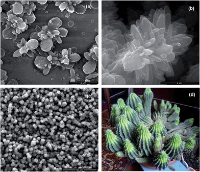 |
| | Fig. 1 (a) SEM image of cactus-like TiO2 flowers array grown at 180 °C, and (b) and (c) SEM images of individual and array of highly branched TiO2 nanorods structures grown at 210 °C, respectively (d) Natural cactus image similar to the cactus-like TiO2 flowers. | |
3.2. Structural and optical properties of TiO2 flowers
Fig. 2a and b depict the XRD patterns of the TiO2 flowers array produced on the substrates in different autoclave temperatures and cooling conditions. The XRD confirms the rutile phase (JCPDS card no. 21-1276 with (110), (101), (111), (211), (002) and (301) planes) of the TiO2 flowers. Besides, the as synthesized TiO2 flowers XRD data disclose the (110) plane peak intensity is prominent with small (002) peak. The relative intensity ratio between planes (110) and (101) of the nanostructures grown at 180 °C and 210 °C is 2.00 and 0.85, respectively. This shows the increase in temperature significantly affected the growth of TiO2 flowers. The higher relative intensity ratio of (110) plane indicates the preferential growth of nanorods in flowers in [001] direction. Also the intense (101) diffraction peak for TiO2 flowers branches suggests more branching of nanorods in horizontal direction to the substrate surface. Fig. 2b shows the XRD patterns of the well grown TiO2 flowers array produced on the substrates in different cooling conditions, and then sintered at 450 °C. These XRD patterns confirm the increase in crystallinity of rutile phase TiO2 flowers by showing sharp XRD peaks from their sintered thin films on substrates.
 |
| | Fig. 2 (a) XRD patterns of thin films of TiO2 flowers made at different temperatures; (b) XRD patterns of sintered films of TiO2 flowers made at different temperatures and cooling conditions. | |
Fig. 3 represents the HRTEM images recorded from the dispersion of TiO2 flowers array obtained at 180 °C. HRTEM images revealed the formation of large aggregates/clusters of rutile TiO2 nanorods in flower assemblies in lower magnification [ESI†], whereas in higher magnification it showed the clusters of nanorods and branched nanorods structures formed predominantly in the (110) and (101) planes as shown in Fig. 3a and b. Further, the SAED analysis revealed the inter-planar distance between adjacent planes was 0.26 nm for the nanorod branches. The structural assignment of diffraction planes (110) (101) (111) and (002) from the respective d-spacing values (0.346, 0.263, 0.221, and 0.140) obtained in SAED analysis is in good agreement with XRD data of the rutile phase TiO2 flowers.
 |
| | Fig. 3 (a and b) HR-TEM images of TiO2 flowers from the supernatant of dispersion; (c) SAED pattern of TiO2 flowers grown at 180 °C. | |
Fig. 4a shows the Raman spectra of TiO2 flowers array developed at different temperatures confirmed their rutile phases as evidenced by the XRD and TEM analyses. In Raman spectra two prominent peaks centered at 444 and 607 cm−1 are predicted as the Eg and A1g modes of rutile TiO2 flowers, respectively. The slight red-shift in Raman peaks of TiO2 flowers (FWHM = 46 and 42 cm−1 for the Eg and A1g mode, respectively) compared to the TiO2 bulk materials, could be due to the phonon confinement in nanostructures.30 In addition to this, a second order Eg Raman peak appearing at ∼241 cm−1 in both samples is due to the multiple phonon scattering, a characteristic of rutile phase TiO2. The non-linear behavior of the Eg peak intensity in the samples made at 180 °C and 210 °C indicates the pronounced light scattering differences, due to the changes in the morphological properties of the samples. Also, the narrowing Raman peaks with high intensity appeared in TiO2 flowers made at 180 °C and 210 °C revealed the formation of better crystalline flowers in high temperatures.
 |
| | Fig. 4 (a) Raman spectra of TiO2 flowers prepared at 180 and 210 °C; (b) UV-visible absorption spectra of different TiO2 flowers and anatase TiO2 nanoparticles (TNP). | |
3.3. Influence of hydrothermal growth temperature and cooling conditions on the TiO2 flowers morphologies
The rapid hydrolysis of titanium(IV) isopropoxide led to the formation of titanium(IV) complex ions and then the dehydration of titanium(IV) complex ions developed different TiO2 nanostructures in different temperatures and cooling conditions. However, the nature of formation of TiO2 nanostructures from titanium(IV) complex ions is critically dependent on the acidity and ligand in the solutions in addition to the external parameters. The acidity of solution by the presence of H+ ions from hydrochloric acid significantly influences the growth of nanostructures and the morphology is mainly determined by incorporation mechanism of the growing crystals in different crystal faces. For rutile TiO2 nanostructures, growth rate in the [001] direction is maximum resultant for stable c-elongated anisotropic crystals growth exhibiting (110) faces.31 Furthermore, the hydrophobic propoxide groups are considered one key factor that control the rapid reaction of titanium(IV) isopropoxide with water. Hence the different morphology formation is mainly dependent on the rate of hydrolysis at different reaction temperature and cooling condition.
During the hydrothermal reaction the nucleation of many TiO2 nanorods at a central long nanorod created small dendritic type TiO2 nanorods on substrates. Also, we believe that the additional nanorods are started growing at certain planes with incorporation of defects at the interface of nanorods trunk during the reaction. Subsequently longer duration of hydrothermal process increased the TiO2 nanorods formation and also increased their aggregation into clusters. Upon abrupt quenching to room temperature, the TiO2 nanorods developed tapered structures from a common nucleation site as observed in the SEM image of sample T1 (Fig. 6). However, the further continuation of hydrothermal process with slow cooling, the growth of TiO2 nanorods became more and more abundant, and new, short nanorod branches started to grow on the surface of the TiO2 nanorods clusters' defect sites at different heights appearing as cactus-like flowers, which was confirmed by monitoring the growth process closely and collecting, analyzing several samples as T2 (at 45 min) and T3 (at 90 min) at two different stages. In a similar fashion, highly branched nanorods array was produced by increasing the reaction temperature to 210 °C and this increase in temperature accelerated the overall growth of TiO2 crystalline nanorods into highly branched nanorods morphology. Hence, the well defined highly branched nanorods array consisting of long trunk and short TiO2 nanorod branches were formed in the slow natural cooling condition maintained up to 90 minutes, after the 2 h hydrothermal reaction at 210 °C. These morphological changes were further confirmed by the SEM images (shown in Fig. 7) of samples obtained after 2 h hydrothermal reaction at 210 °C with subsequent different cooling conditions such as S1 (quenched), S2 (at 45 min) and S3 (at 90 min). Moreover the morphological analysis of all these samples indicated the formation of highly branched structures was favorable only under slow cooling conditions.
 |
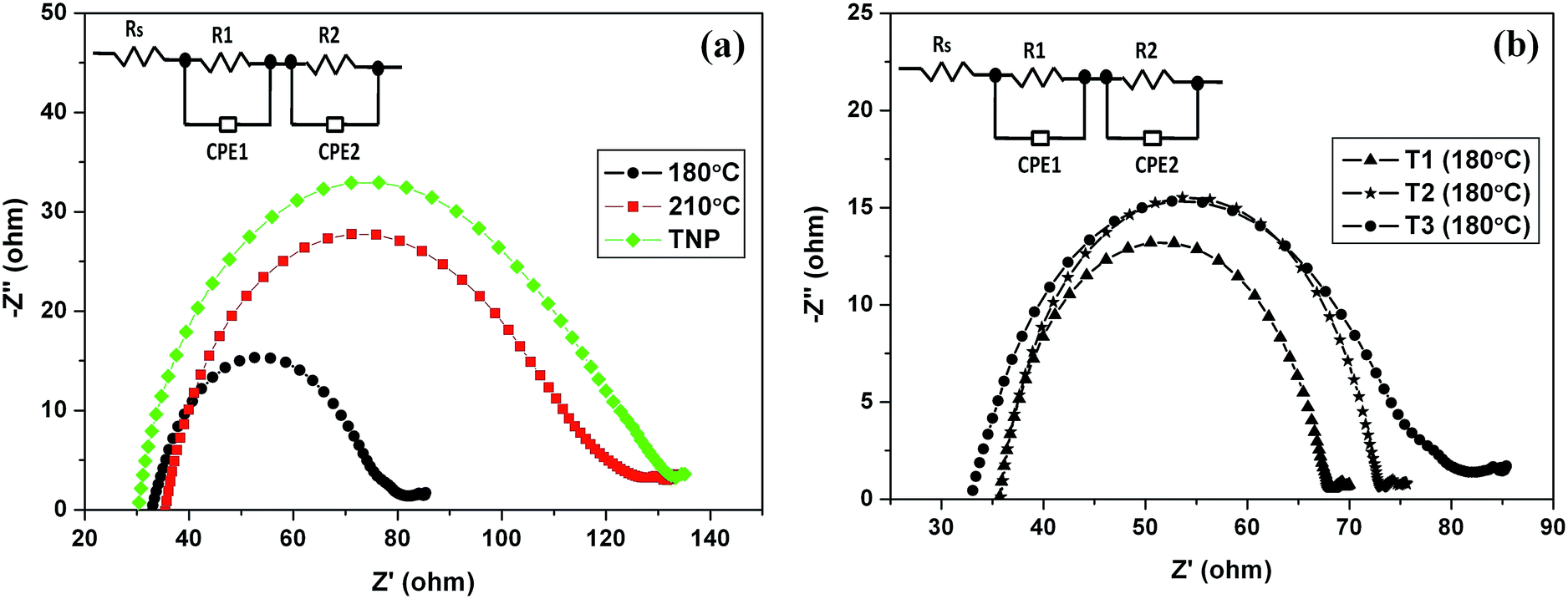
| | Fig. 5 (a) Nyquist plots of the DSSCs made of TiO2 flowers grown at 180, 210 °C and TiO2 nanoparticles. The inset shows the equivalent circuit for the impedance spectrum. RS: serial resistance; R1: charge-transfer resistance of Pt electrode; R2: charge-transfer resistance of photoanode; CPE: a constant phase element; (b) Nyquist plots of the DSSCs made of TiO2 flowers grown at 180 °C with different cooling conditions. | |
 |
| | Fig. 6 (T1), (T2) and (T3) are representative SEM images of the TiO2 flowers obtained at different cooling conditions after heating up to 180 °C for 2 h. | |
 |
| | Fig. 7 (S1), (S2) and (S3) are representative SEM images of the TiO2 flowers obtained at different cooling conditions after heating up to 210 °C for 2 h. | |
The UV-visible absorption spectra of the thin films of well grown TiO2 flowers are shown in the Fig. 4b. The highly branched nanorods array film showed better diffuse reflectance than the cactus array film which indicates the highly branched nanorods array favors the light scattering effect more in their thin film. However the transparent layer obtained at 150 °C did not show any diffuse reflectance spectrum. This indicates the lack of formation of sufficient TiO2 layer to scatter the light when the thin film is developed at the temperature 150 °C or below. The same type of observations in the XRD and Raman studies has further supported the requirement of higher temperature for the growth of highly crystalline TiO2 flowers on substrates. And when the growth temperature is increased to 210 °C more branched nanostructures developed on substrates, substantially improved the light scattering of the entire film. The crystalline TiO2 flowers obtained at the growth temperature 180 °C as three different samples T1, T2 and T3 in different cooling rates showed marginal differences in their diffused reflectance values indicating the better light scattering ability for the TiO2 nanostructures grown in slower cooling conditions [ESI†].
Furthermore, to attain better insight into the charge transfer dynamics within TiO2 flowers DSSCs, electrochemical impedance spectroscopy (EIS) was performed. Fig. 5a shows the Nyquist plots of the DSSCs based on TiO2 flowers prepared at 180, 210 °C and TiO2 nanoparticles. An equivalent circuit was simulated to fit the Nyquist plots to estimate the resistance parameters and the corresponding parameters are listed in Table 1. In the Nyquist plots, the semicircles in the high-frequency region corresponded to the charge transfer resistance at the interface of counter electrode/redox electrolyte (R2), and the semicircles in the low-frequency region corresponded to the charge-transfer process occurring at the TiO2–dye–electrolyte interface (R3).32 The semicircle belongs to the Nernstian diffusion process is usually observed in low frequencies (<0.1 Hz). In particular, there was a huge difference exhibited in the large semicircles. As shown in the Fig. 5a and Table 1, the recombination resistance (R2) of DSSCs increased significantly from 48.67 Ω cm−2 to 89.78 Ω cm−2 with the increase of growth temperature from 180 to 210 °C. This increase in resistance at the TiO2–electrolyte interface suppressed the charge recombination processes in the highly branched nanostructures which can facilitate the fast electron transport within the nanorods. This effect eased a smooth and efficient electron transfer in the highly branched nanorods morphology obtained at 210 °C. Moreover the recombination resistance of highly branched TiO2 flowers photoanodes was compared with the anatase TiO2 nanoparticle (TNP) photoanode, which also indicated a superior electron transport with suppressed recombination in the highly branched nanorods. Fig. 5b shows the Nyquist plots of DSSCs constructed from the TiO2 flowers photoanodes prepared in different cooling conditions as T1, T2 and T3 samples, after 2 h hydrothermal treatment at 180 °C. The recombination resistance (R2) of DSSCs increased significantly from 32.37 Ω cm−2 to 48.67 Ω cm−2 for a longer duration (90 min) cooled TiO2 flowers photoanode. Also, T1, T2 and T3 samples Nyquist plots comparison showed a significant increase in the recombination resistance (R2) for DSSCs bearing more branched nanorods in their photoanodes.
Table 1 EIS parameter of different flowers photoanode based DSSCs
| Sample |
RS (Ω cm−2) |
R2 (Ω cm−2) |
Rsh (Ω cm−2) |
Electron lifetime (ms) |
| 180 °C |
33.34 |
48.67 |
700 |
6.47 |
| 210 °C |
35.75 |
89.78 |
637 |
11.70 |
| TNP |
30.52 |
101.02 |
1105 |
6.57 |
The bode phase plots demonstrated the frequency peak for 180 °C TiO2 flowers at 24.62 Hz and frequency for 210 °C TiO2 flowers at 13.64 Hz [ESI†], indicating the shift of the peak from high frequency to low frequency revealed a more rapid electron transport process.33 The mean electron lifetime (τe) was calculated from the following relation:
whereas the
fmax was maximum of the intermediate frequency semi-circle, which showed the mean electron lifetimes of the 180 °C and 210 °C samples were 6.47 ms and 11.70 ms, respectively. These results suggest the long electron lifetime and slow recombination in highly branched nanorods structures grown at 210 °C improved the charge-collection efficiency and the energy conversion efficiency of their DSSC.
3.4. Photovoltaic characteristics of rutile TiO2 flowers photoanodes
Fig. 8a and b show the compared photocurrent–voltage (J–V) characteristics of all the DSSCs of TiO2 flowers under a 1.5 AM (global) simulated solar illumination. The short-circuit current density (Jsc), the open-circuit voltage (Voc), the fill factor (FF), and the overall light conversion efficiency (η) derived from the J–V curves for rutile TiO2 flower arrays DSSCs are summarized in Table 2. From Fig. 8 and Table 2, it can be seen that the Jsc, Voc, and FF for the DSSC fabricated using the TiO2 flowers photoanode of highly branched nanorods obtained at 210 °C (Jsc = 10.04 mA cm−2, Voc = 0.68 V, FF = 45%) show noticeable improvement over the DSSC fabricated using the TiO2 flowers photoanode of cactus-like nanostructures obtained at 180 °C (Jsc = 8.14 mA cm−2, Voc = 0.64 V, FF = 51%). A higher value of short-circuit current density would result in the higher power conversion efficiency of solar cell34 and therefore the increase in short-circuit current density can improve the power conversion efficiency in highly branched nanorods DSSC though the fill factor value obtained is lower than other DSSCs. The photocurrent density in DSSCs is dependent on the amount of photo-generated electrons, the electron injection efficiency from dyes to semiconductor, and the competitive recombination kinetics between the injected electrons and oxidized dye or tri-iodine ions in the electrolyte.35 Generally, the electron injection efficiency is dependent on the relative energy levels of dye and TiO2 semiconductor, lifetime of photo-generated electrons within the dye, and the density of electron-accepting states in the semiconductor.36 Hence, by assuming the electron injection efficiency between N719 dye and TiO2 semiconductor is consistent; the differences in the short circuit current density of rutile TiO2 flowers could have resulted from the changes in competitive recombination kinetics between the injected electrons of various nanostructured photoanodes and oxidized dye or tri-iodine ions in the electrolyte.37
Table 2 Photovoltaic properties of different TiO2 flowers based DSSCs
| Photoanode |
Jsc (mA cm−2) |
Voc (V) |
FF |
η (%) |
| 210 °C |
10.04 |
0.68 |
0.45 |
3.07 |
| T1 (180 °C) |
3.83 |
0.58 |
0.47 |
1.05 |
| T2 (180 °C) |
5.72 |
0.61 |
0.50 |
1.76 |
| T3 (180 °C) |
8.14 |
0.64 |
0.51 |
2.66 |
| TNP |
13.96 |
0.74 |
0.59 |
6.09 |
 |
| | Fig. 8 (a) Comparative J–V curves of TiO2 flowers and TiO2 nanoparticles; (b) J–V curves of TiO2 flowers prepared in different cooling conditions. | |
Moreover, the morphological differences in the TiO2 flowers' nanostructures affected the internal surface area and light harvesting features in each of their photoanodes with different dye loading capabilities. The highly branched nanorods morphologies exhibited better dye loading capabilities due to the increased internal surface area which was confirmed by dye adsorption studies and surface roughness calculations [ESI†]. Also the better light scattering ability in the highly branched nanorods further supported the improvement in the photovoltaic characteristics of their DSSC photoanode. Despite the existence of superior light scattering ability and the longer electron recombination lifetime in the highly branched nanorods, their DSSCs showed low fill factor, Voc and power conversion efficiency when comparing to the anatase TiO2 nanoparticles based DSSC. The low efficiency was mainly due to the low fill factor which probably resulted from the back reaction between photoexcited electrons in TiO2 flowers and tri-iodide ions in the filling electrolyte. The back reaction is obvious in the low value of the shunt resistance, Rsh = (dV/dI)v=0, which is significantly lower for TiO2 flowers compared to TiO2 nanoparticles in the I–V curve recorded under illumination, as can be seen in Fig. 8a and Table 1.
Furthermore, the samples T1, T2 and T3 also showed an increasing trend in the short-circuit current density though high reflectance and light scattering ability was also observed in the T1 sample. This trend could be the result of poor internal surface area affecting the dye loading capability of the photoanode of T1 sample. Besides, the lower recombination resistance observed in the T1 photoanode compared to the T3 photoanode could result to the poor electron lifetime and faster recombination. These results were closely matching to the similar type of observations previously encountered in the hierarchical assembly of ZnO nanowires.38 Also these results confirmed the highly branched nanorods structures have the adequate morphological features for better photovoltaic performance among the synthesized TiO2 flowers (Fig. 9).
 |
| | Fig. 9 Schematic diagram of the DSSC with highly branched TiO2 nanorods as the photoanode on FTO, showing the processes involved in current generation. | |
4. Conclusions
The rutile TiO2 flowers categorized as cactus-like flowers and highly branched nanorods were successfully synthesized by one-step facile hydrothermal process without the presence of any surfactant or template. The TiO2 flowers' size and morphology were controlled by the growth temperature and subsequent cooling conditions of the hydrothermal process. The Raman and UV-visible reflectance analyses confirmed these rutile phase nanostructures possessing strong phonon confinement effect and light scattering ability in the TiO2 flowers. These results suggest that the growth temperature affected the morphological properties of nanostructures of TiO2 flowers. TiO2 flowers grown in elevated temperature (at 210 °C) and slow cooling resulted to the highly branched nanorods structures demonstrating superior light scattering ability in the thin film. The EIS and photovoltaic characteristics of the highly branched nanorods in dye sensitized solar cells (DSSCs) showed better performance among the synthesized TiO2 flowers with a maximum power conversion efficiency of 3.07% due to its good crystallization, higher charge transfer resistance and fast charge transport, and superior light scattering ability. Moreover, the hierarchical TiO2 flowers demonstrated better light scattering ability and longer electron lifetimes comparing to the anatase TiO2 nanoparticles but possess poor surface area, dye loading capability and low shunt resistance in their photoanodes reduced the DSSCs performance. However, we introduce this simple method to control the morphological and physical properties of TiO2 nanostructures which can help to produce new structured materials with superior light scattering ability for the improved light-harvesting efficiency and performance in dye sensitized solar cells and other related applications.
Acknowledgements
The financial support from DRDO and COE of AMGT for this research is gratefully acknowledged. D. K. thanks SAIF, IITM for providing SEM and XRD facilities.
Notes and references
- B. O'Regan and M. Grätzel, Nature, 1991, 353, 737 CrossRef
 .
. - A. Yella, H. W. Lee, H. N. Tsao, C. Y. Yi, A. K. Chandiran, M. K. Nazeeruddin, E. W. G. Diau, C. Y. Yeh, S. M. Zakeeruddin and M. Grätzel, Science, 2011, 334, 629 CrossRef CAS PubMed .
- X. Y. Lai, J. E. Halpert and D. Wang, Energy Environ. Sci., 2012, 5, 9944 Search PubMed .
- L. X. Yi, Y. Y. Liu, N. L. Yang, Z. Y. Tang, H. J. Zhao, G. H. Ma, Z. G. Su and D. Wang, Energy Environ. Sci., 2013, 6, 835 CAS .
- M. Grätzel, J. Photochem. Photobiol., A, 2004, 164, 3 CrossRef PubMed .
- J. W. Shiu, C. M. Lan, Y. C. Chang, H. P. Wu, W. K. Huang and E. W. G. Diau, ACS Nano, 2012, 6, 10862 CAS .
- S. Ito, T. N. Murakami, P. Comte, P. Liska, C. Gratzel, M. K. Nazeeruddin and M. Grätzel, Thin Solid Films, 2008, 516, 4613 CrossRef CAS PubMed .
- A. C. Fisher, L. M. Peter, E. A. Ponomarev, A. B. Walker and K. G. U. Wijayantha, J. Phys. Chem. B, 2000, 104, 949 Search PubMed .
- W. Q. Wu, J. Y. Liao, H. Y. Chen, X. Y. Yu, C. Y. Su and D. B. Kuang, J. Mater. Chem., 2012, 22, 18057 RSC .
- Y. Li, H. Wang, Q. Y. Feng, G. Zhou and Z. S. Wang, Energy Environ. Sci., 2013, 6, 2156 CAS .
- F. Shao, J. Sun, L. Gao, S. W. Yang and J. Q. Luo, J. Phys. Chem. C, 2011, 115, 1819 CAS .
- Y. H. Wang, H. X. Yang and H. M. Xu, Mater. Lett., 2010, 64, 164 CrossRef CAS PubMed .
- B. Liu and E. S. Adyil, J. Am. Chem. Soc., 2009, 131, 3985 CrossRef CAS PubMed .
- X. Xin, J. Wang, W. Han, M. Ye and Z. Lin, Nanoscale, 2012, 4, 964 RSC .
- A. I. Hochbaum and P. D. Yang, Chem. Rev., 2010, 110, 527 CrossRef CAS PubMed .
- C. Xu, J. Wu, U. V. Desai and D. Gao, J. Am. Chem. Soc., 2011, 133, 8122 CrossRef CAS PubMed .
- W. Q. Wu, B. X. Lei, H. S. Rao, Y. F. Xu, Y. F. Wang, C. Y. Su and D. B. Kuang, Sci. Rep., 2013, 3, 1352 Search PubMed .
- J. Y. Liao, B. X. Lei, H. Y. Chen, D. B. Kuang and C. Y. Su, Energy Environ. Sci., 2012, 5, 5750 Search PubMed .
- W. Q. Wu, B. X. Lei, H. S. Rao, Y. F. Xu, Y. F. Wang, C. Y. Su and D. B. Kuang, Sci. Rep., 2013, 3, 1352 Search PubMed .
- W. Yang, F. Wan, Y. Wang and C. Jiang, Appl. Phys. Lett., 2009, 95, 133121 CrossRef PubMed .
- J. Shi, Y. Hara, C. L. Sun, M. A. Anderson and X. D. Wang, Nano Lett., 2011, 11, 3413 CrossRef CAS PubMed .
- D. H. Lee, Y. Rho, F. I. Allen, A. M. Minor, S. H. Ko and C. P. Grigoropoulos, Nanoscale, 2013, 5, 11147 RSC .
- J. Y. Liao, B. X. Lei, D. B. Kuang and C. Y. Su, Energy Environ. Sci., 2011, 4, 4079 CAS .
- X. Sheng, D. He, J. Yang, K. Zhu and X. Feng, Nano Lett., 2014, 14, 1848 CrossRef CAS PubMed .
- W. Q. Wu, H. S. Rao, H. L. Feng, X. D. Guo, C. Y. Su and D. B. Kuang, J. Power Sources, 2014, 260, 6 CrossRef CAS PubMed .
- C. Zha, L. Shen, X. Zhang, Y. Wang, B. A. Korgel, A. Gupta and N. Bao, ACS Appl. Mater. Interfaces, 2014, 6, 122 CAS .
- S. S. Mali, H. Kim, C. S. Shim, P. S. Patil, J. H. Kim and C. K. Hong, Sci. Rep., 2013, 3, 3004 Search PubMed .
- M. Rawolle, M. A. Niedermeier, G. Kaune, J. Perlich, P. Lellig, M. Memesa, Y. J. Cheng, J. S. Gutmann and P. Müller-Buschbaum, Chem. Soc. Rev., 2012, 41, 5131 RSC .
- A. Nikhil, D. A. Thomas, S. Amulya, S. Mohan Raj and D. Kumaresan, Sol. Energy, 2014, 106, 109 CrossRef CAS PubMed .
- S. S. Mali, C. A. Betty, P. N. Bhosale and P. S. Patil, CrystEngComm, 2011, 13, 6349 RSC .
- A. Kumar, A. R. Madaria and C. Zhou, J. Phys. Chem. C, 2010, 114, 7787 CAS .
- F. Fabregat-Santiago, J. Bisquert, E. Palomares, L. Otero, D. B. Kuang, S. M. Zakeeruddin and M. Grätzel, J. Phys. Chem. C, 2007, 111, 6550 CAS .
- S. S. Mali, H. Kim, C. S. Shim, W. R. Bae, N. L. Tarwal, S. B. Sadale, P. S. Patil, J. –H. Kim and C. K. Hong, CrystEngComm, 2013, 15, 5660 RSC .
- T. P. Chou, Q. F. Zhang, G. F. Fryxell and G. Z. Cao, Adv. Mater., 2007, 19, 2588 CrossRef CAS PubMed .
- R. A. Rao and V. Dutta, Nanotechnology, 2008, 19, 445712 CrossRef PubMed .
- Q. F. Zhang, C. S. Dandeneau, X. Y. Zhou and G. Z. Cao, Adv. Mater., 2009, 21, 4087 CrossRef CAS PubMed .
- F. Xu, M. Dai, Y. Lu and L. Sun, J. Phys. Chem. C, 2010, 114, 2776 CAS .
- H. M. Cheng, W. H. Chiu, C. H. Lee, S. Y. Tsai and W. F. Hsieh, J. Phys. Chem. C, 2008, 112, 16359 Search PubMed .
Footnote |
| † Electronic supplementary information (ESI) available: Additional SEM, TEM images, bode plots and dye adsorption characterization details are included in the supporting information. See DOI: 10.1039/c4ra05298f |
|
| This journal is © The Royal Society of Chemistry 2014 |
Click here to see how this site uses Cookies. View our privacy policy here.