DOI:
10.1039/C4RA05173D
(Paper)
RSC Adv., 2014,
4, 39174-39183
In vitro DNA binding, molecular docking and antimicrobial studies on a newly synthesized poly(o-toluidine)–titanium dioxide nanocomposite†
Received
31st May 2014
, Accepted 20th August 2014
First published on 20th August 2014
Abstract
A poly(o-toluidine)–titanium dioxide (POT–TiO2) nanocomposite has been synthesized for the first time by in situ chemical oxidative polymerization of o-toluidine (OT) in the presence of titanium dioxide (TiO2) nanoparticles. FTIR, SEM, TEM, XRD, TGA and DTA were used to characterize the POT–TiO2 nanocomposite. The characterization results confirmed that there is a strong interaction between POT and TiO2 nanoparticles and the nanocomposite showed higher thermal stability than pristine POT. The in vitro DNA binding studies of POT and POT–TiO2 nanocomposite with ct-DNA in physiological buffer (pH-7.4) were investigated using spectrophotometry and circular dichroism. The absorption spectra of the POT and POT–TiO2 nanocomposite with DNA showed a hypochromic effect. The four types of 3D molecular field descriptors or field points as extrema of electrostatic, steric, and hydrophobic fields are described. These field points are used to define the properties necessary for a molecule to bind in a characteristic way into a specified active site. A molecular docking simulation was used to predict the modes of interactions of the drugs (POT and POT–TiO2) with DNA. The molecular docking results indicated that the modes of interactions between the two (POT and POT–TiO2) and DNA helix can be considered as groove binding. Moreover, the comparative antimicrobial activities of POT and its POT–TiO2 nanocomposite were tested and were found to exhibit antibacterial activity against Gram positive as well as Gram negative bacterial strains at micromolar concentration.
1. Introduction
Conducting polymers have attracted more and more attention and a lot of research has been done to probe their electrical, thermal and sensing properties since their discovery three decades ago.1–6 Amongst these conducting polymers, polyaniline and its derivatives like poly(o-toluidine), poly(o-anisidine), poly(3-methoxyaniline) etc. have been widely applied in various fields due to their good electrical and electrochemical properties, environmental stability to water and oxygen and ease of preparation at low cost.7–10 These applications mainly focus on its interesting electrical conductivity. In view of their poor chemical, thermal and mechanical properties, their use in biomedical, biosensing applications and device formation is restricted. To solve this problem, a considerable amount of work has been done in recent years to prepare composites/nanocomposites of polyaniline and its derivatives with other conventional polymers or nanoparticles.3,8 These composites are expected to display new properties due to the synergism between the constituents and thus may find applications in several fields such as estimation of bacteria,11 photocatalysis,12–14 biosensor,15 enzyme immobilization,15 sensor for detection of heavy metals, toxic gases, pesticides etc.2–7
DNA based nanotechnology, in many ways, has been one of the most intensively studied fields in recent years that involves the use and the creation of bio-inspired materials and their technological applications for highly selective biosensing, nanoarchitecture engineering and nanoelectronics. Increasing researches have been directed to develop a fundamental understanding that how the interactions between the polymer nanocomposite and DNA molecules could alter DNA molecular structure and its biochemical activities.16 The considerable interaction of POT–TiO2 nanocomposite is based on the surface area as the size of TiO2 nanoparticles decrease, the surface to volume ratio and specific area significantly increase. The relatively high surface area is extremely beneficial for the use of POT–TiO2 nanocomposite. It extends the interaction between surface of POT–TiO2 nanocomposite and the interacting media. The surface area of TiO2 is very influential on the various interactions because they occur primarily on the surface or interface. POT–TiO2 nanocomposite surface has a high affinity for phosphate groups; this can lead to various nonspecific interactions between POT–TiO2 nanocomposite and biological materials, such as proteins and DNA and cease their replication. The striking feature of this nanocomposite is the dual nature of POT–TiO2 nanocomposite under pH scales make them different (unusual and unique) to the other composites. The relative negative charge of TiO2 nanoparticles at high pH and positive charge on drug was easily self assembled onto the surface of TiO2 via electrostatics and bring drug to specific targets in the body and furthermore, surface charges of TiO2 nanoparticles turned positive at lower pH which blunted the electrostatic interaction between drugs and TiO2 nanoparticles and facilitated the drug release process without any change in the nature of the model drug. DNA binding studies, molecular docking on nanoparticles, metal complexes and their potential applications in various fields has been reported.16,17 However conducting polymer based organic–inorganic nanocomposite with polyvalent sites has not been reported in the field of DNA-binding and molecular docking studies. Here in, we have synthesized a new conductive nanocomposite of poly(o-toluidine) and TiO2 nanoparticle by in situ chemical polymerization technique. The newly synthesized nanocomposite is used as a new DNA binding material attempted articulately for the first time to the best of our knowledge for molecular modeling of POT and POT–TiO2 nanocomposite by using field point methodology and created pharmacophore models for investigating the possible ligand binding sites. These studies demonstrate that compounds with wide chemical diversity and that analysis of such compounds can enhance our understanding of their ligand–receptor interaction.18 Moreover, computer-aided molecular docking studies were performed to visualize the binding mode of the POT and its POT–TiO2 nanocomposite with DNA bases.
2. Experimental
2.1. Materials
O-Toluidine monomer (Merck, Germany). Ammonium peroxydisulphate (APS) (S D Fine Chem., India), Hydrochloric acid (S D Fine Chem., India) (AR grade), and Titanium dioxide (TiO2 ∼ 50 nm) from MK Nano Canada were used as received and Methanol from S D Fine Chem., India. Calf Thymus DNA, Ethidium Bromide was purchased from Sigma Aldrich, USA.
2.2. Synthesis of poly-o-toluidine
Poly-o-toluidine was prepared by mixing in similar volume ratios of the solution of ammonium persulphate prepared in 1 M HCl into o-toluidine prepared in 1 M HCl with continuous stirring by a magnetic stirrer for 2 h at 0 °C, a green colored gel was obtained,8,19 which was filtered, repeatedly washed with distilled water to remove the excess of acid and impurities and dried at 60 °C for 8 h in an oven.
2.3. Synthesis of poly-o-toluidine–TiO2 nanocomposite
POT–TiO2 nanocomposite was prepared by in situ oxidative polymerization1,2,11 of o-toluidine in the presence of TiO2 using ammonium persulphate as an oxidizing agent. The TiO2 nanoparticles were ultrasonicated in 1 M HCl for 1 h before pouring it into solution of o-toluidine and polymerization was effected by the addition of solution of oxidant ammonium persulphate made in 1 M HCl. The addition of oxidant solution led to the polymerization of adsorbed o-toluidine on TiO2 nanoparticles resulting in the light black colored solution which later converted to greenish black precipitate and was kept under continuous stirring for 20 h. The reaction mixture was then filtered, washed with double distilled water and methanol to remove excess acid. The nanocomposite thus prepared was dried at 60 °C for 8 h in an oven, which was converted into fine powders and was stored in desiccator for further investigations. The conditions of preparation of POT and POT–TiO2 nanocomposite are given in Table S1 (in ESI†). The synthesized POT–TiO2 nanocomposite was further used for structural elucidation, morphological, thermal, DNA binding and antibacterial investigations.
2.4. Characterization
2.4.1. Fourier transform infra red (FTIR) studies. The FTIR spectrum of POT and POT–TiO2 nanocomposite were obtained using FTIR spectrophotometer (Perkine Elmer, USA, model Spectrum-BX) in the original form dried at 40 °C were taken by KBr disc method at room temperature.
2.4.2. Scanning electron microscopy (SEM) and EDAX studies. The scanning electron microscopy (SEM) was carried out using the fine powder of the POT and POT–TiO2 nanocomposite on a carbon tape in a scanning electron microscope (LEO 435-VF) at an accelerating voltage of 15 kV. The elemental analysis of POT–TiO2 nanocomposite was determined using the Oxford Instruments INCAx-sight energy dispersive X-ray (EDAX) spectrometer equipped SEM.
2.4.3. Transmission electron microscopy (TEM) studies. Micrograph of the ‘organic–inorganic’ nanocomposite material POT–TiO2 was obtained by transmission electron microscopy JEOL TEM (JEM 2100F) instrument to determine the particle size of nanocomposite. The diameter of the POT–TiO2 nanocomposite was measured using image analysis software ImageJ 1.44 (jdk6-setup) by randomly selecting 100 particles of the POT–TiO2 nanocomposite in the TEM image to acquire the size distribution histogram.20
2.4.4. X-ray analysis. X-ray diffraction patterns (XRD) of POT and POT–TiO2 nanocomposite synthesized and described in this work were obtained at PHILIPS PW1710 instrument equipped with a Cu anode, automatic divergence slit and a graphite monochromator, under the following experimental conditions: CuKα radiation, 1.54 Å; generator tension, 45 kV; generator current, 40 mA; intensity ratio (a2/a1), 0.500.
2.4.5. TGA and DTA studies. The thermal stability was investigated by thermogravimetric analysis (TGA) and differential thermal analysis (DTA) using thermal analyzer-V2.2A DuPont 9900. The samples were heated from 30 °C to 1000 °C at the rate of 10 °C min−1 in the nitrogen atmosphere at the flow rate of 200 mL min−1.
2.5. Field points of POT–TiO2 nanocomposite
The structure of the POT and POT–TiO2 nanocomposite were drawn using Chem Draw Ultra 12.0 & Chem3D Pro 12.0 software and subsequently these structures were energetically minimized using MOPAC with MM2 and saved MDL molfile (mol). Field points were performed to identify the surface properties around the complexes using Torch Lite software of Cresset-group (Cresset Biomolecular Discovery Ltd). A representative field point pattern is shown in Fig. 11. Larger field points are indicative of stronger points of potential interaction.
2.6. Molecular docking
The retrieved protein, G-quadruplex structure (PDB 143D)21 (Fig. 1) was improved by the import and preparation option of MMV software (http://www.molegro.com) and missing bond order, hybridization state, angle and flexibility for achieving reliable potential binding site in receptor. The units of POT and its POT–TiO2 were designed and structure was analyzed using Chem Draw Ultra3D software and then these structures were energetically minimized using MM2 force field with RMS Gradient set to 0.0001, and coordinates of compounds were checked using PRODRG. Discovery studio 3.5 Client22 and iGEMDOCK23 were used to perform ligand–receptor interaction, visualization of the docked pose and binding affinity of POT and its POT–TiO2 nanocomposite.
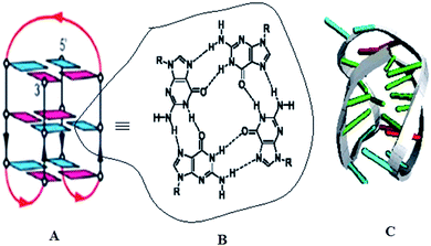 |
| | Fig. 1 (A) stacking to form an intramolecular structure with binding sites that are targeted by POT and its POT–TiO2, (B) detailed view of the central G-quartet and (C) DNA motif. | |
2.7. DNA binding studies
2.7.1. Sample preparation. 1 mg of calf thymus DNA was dissolved in 1 ml 20 mM phosphate buffer (pH = 7.4) at 298 K with occasional stirring up to 24 h to ensure the formation of a homogenous solution. The concentration of the DNA was determined spectrophotometrically using 2260 = 6600 M−1 cm−1 as reported earlier.24 The stock solution of POT and POT–TiO2 nanocomposite were first dissolved in DMSO and then final stock solution was prepared in the same buffer (volume of DMSO does not exceed 5% by v/v). All experiments were carried out at 298 K in 2 mM phosphate buffer pH (7.4) unless otherwise mentioned.
2.7.2. pH determination. pH measurements were carried out on Mettler Toledo pH meter (Seven Easy S20-K) using Expert “Pro3 in 1” type electrode. The least count of the pH meter was 0.01 pH unit.
2.7.3. UV-Visible spectroscopy. The UV-measurements of calf thymus DNA were recorded on a UV-1800 Shimadzu spectrophotometer by using a cuvette of 1 cm path length. The absorbance values of POT and POT–TiO2 nanocomposite in the absence and presence of DNA were recorded in the range of 240–300 nm. Appropriate blanks corresponding to the DNA solution and buffer were subtracted to correct the base line.
2.7.4. Fluorescence spectroscopy. Fluorescence measurements were performed on a Shimadzu spectrofluorimeter, model RF-5301 equipped with PC. The fluorescence spectra were measured at 25 ± 0.1 °C with a 1 cm path length cell. Both excitation and emission slits were set at 5 nm. Intrinsic fluorescence was measured by exciting the ct-DNA solution at 480 nm and emission spectra was recorded in the range of 550–700 nm. DNA concentration was 10 μM and the concentrations of POT and POT–TiO2 nanocomposite were 0 to 21 μM.
2.7.5. Circular dichroism measurements. To monitor the secondary structural changes in ct-DNA at different concentrations POT and POT–TiO2 nanocomposite were carried out on JASCO-J 813 spcetropolarimeter equipped with a Peltier-type temperature controller at 25 °C using a quartz cell a path length of 0.1 cm. Two scans were accumulated at a scan speed of 100 nm min−1, with data being collected in the range of 220–320. CD spectra of ct-DNA in absence and presence of POT and POT–TiO2 nanocomposite (0, 10 and 10 μM) were recorded. In addition respective blanks were subtracted.
2.8. Antibacterial activity
Escherichia coli, Staphylococcus aureus, Staphylococcus epidermidis, and Proteus mirabilis were sub-cultured in agar medium for 18 hours at 37 °C. The bacterial cells were suspended and incubated in saline solution, according to the McFarland protocol, to achieve a suspension of ∼105 CFU per mL. Bacterial suspension (10 mL) and sterile agar containing antibiotic (10 mL) were mixed at 40 °C and poured on agar plate in a laminar flow cabinet. Further, five paper disks of 6.0 mm diameter were fixed on to nutrient agar plate. In vitro screening for antibacterial activity and cell culture was done using disk diffusion method, with minor modifications as following: test compounds (1 mg each) were dissolved in 100 mL dimethyl sulfoxide (DMSO) to get stock solutions which were further diluted to achieve working solutions and were poured over disk plates. Ciprofloxacin and DMSO were used as positive (standard drug) and negative control, respectively. To estimate bacterial susceptibility to the test compounds, an inhibitory zone formation was evaluated after 18 h of incubation at 37 °C. Furthermore, the results were compared with the positive control and at the minimum inhibitory concentration (MIC), the lowest concentration of drug candidate required to arrest the growth of bacteria, the zone of inhibitions were determined. Standard inoculum of 105 CFL per mL was used to MIC, using macro-dilution tests. Final concentrations of 400, 200, 100, 50, 12.5, 6.25 and 3.125 μg mL−1 were obtained for test compounds, by diluting stocks in DMSO. Each test compound concentration condition was evaluated for antibacterial activity, by adding 100 mL of a 24 hours old inoculum. MIC values, for different test compounds, were determined visually after incubation of 18 hours at 37 °C.11
3. Results and discussion
3.1. FT-IR analysis
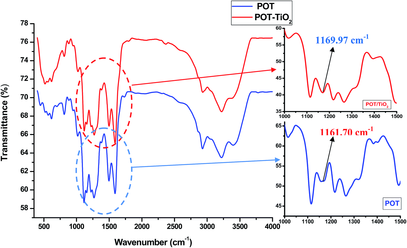
The FTIR spectra of POT and POT–TiO2 nanocomposite are shown in Fig. 2. The most intense broad band at 3209.40 cm−1 with a shoulder at 2927 cm−1 corresponds to N–H stretching vibration and in plane deformation of –CH methylene group respectively.25 The bands at 1493 cm−1 and 1590 cm−1 may be attributed to C![[double bond, length as m-dash]](https://www.rsc.org/images/entities/char_e001.gif) N and CC stretching modes of vibration for the benzenoid units (N–B–N, where B = benzenoid ring) and quinoid (–N = Q = N–, where Q = quinoid ring) respectively,19,26 while the peak at 1264 cm−1 may be assigned to the C–N stretching mode of benzenoid units. The peak at 813 cm−1 may be assigned to an out of plane bending vibration of C–H of 1,4-disubstituted benzenoid rings which confirmed the formation of POT. These results are in good agreement with previous spectroscopic characterization of POT.19 However in the case of POT–TiO2 nanocomposite, the most of the main peaks for POT and POT–TiO2 are similar, except the peak at 1161.70 cm−1 of POT spectrum, which shifts slightly to a higher wave number to 1169.97 cm−1 for the spectra of POT–TiO2 nanocomposite. The apparent change clearly confirms that degree of charge delocalization has been enhanced for the polymer backbone due to the interfacial interaction between the TiO2 nanoparticles and POT. Finally, it may be inferred that almost the shift in peak is due to some sort of interaction between the POT and TiO2 nanoparticles in the polymer matrix.
N and CC stretching modes of vibration for the benzenoid units (N–B–N, where B = benzenoid ring) and quinoid (–N = Q = N–, where Q = quinoid ring) respectively,19,26 while the peak at 1264 cm−1 may be assigned to the C–N stretching mode of benzenoid units. The peak at 813 cm−1 may be assigned to an out of plane bending vibration of C–H of 1,4-disubstituted benzenoid rings which confirmed the formation of POT. These results are in good agreement with previous spectroscopic characterization of POT.19 However in the case of POT–TiO2 nanocomposite, the most of the main peaks for POT and POT–TiO2 are similar, except the peak at 1161.70 cm−1 of POT spectrum, which shifts slightly to a higher wave number to 1169.97 cm−1 for the spectra of POT–TiO2 nanocomposite. The apparent change clearly confirms that degree of charge delocalization has been enhanced for the polymer backbone due to the interfacial interaction between the TiO2 nanoparticles and POT. Finally, it may be inferred that almost the shift in peak is due to some sort of interaction between the POT and TiO2 nanoparticles in the polymer matrix.
 |
| | Fig. 2 FTIR spectra of POT and POT–TiO2 nanocomposite. | |
3.2. Morphological analysis
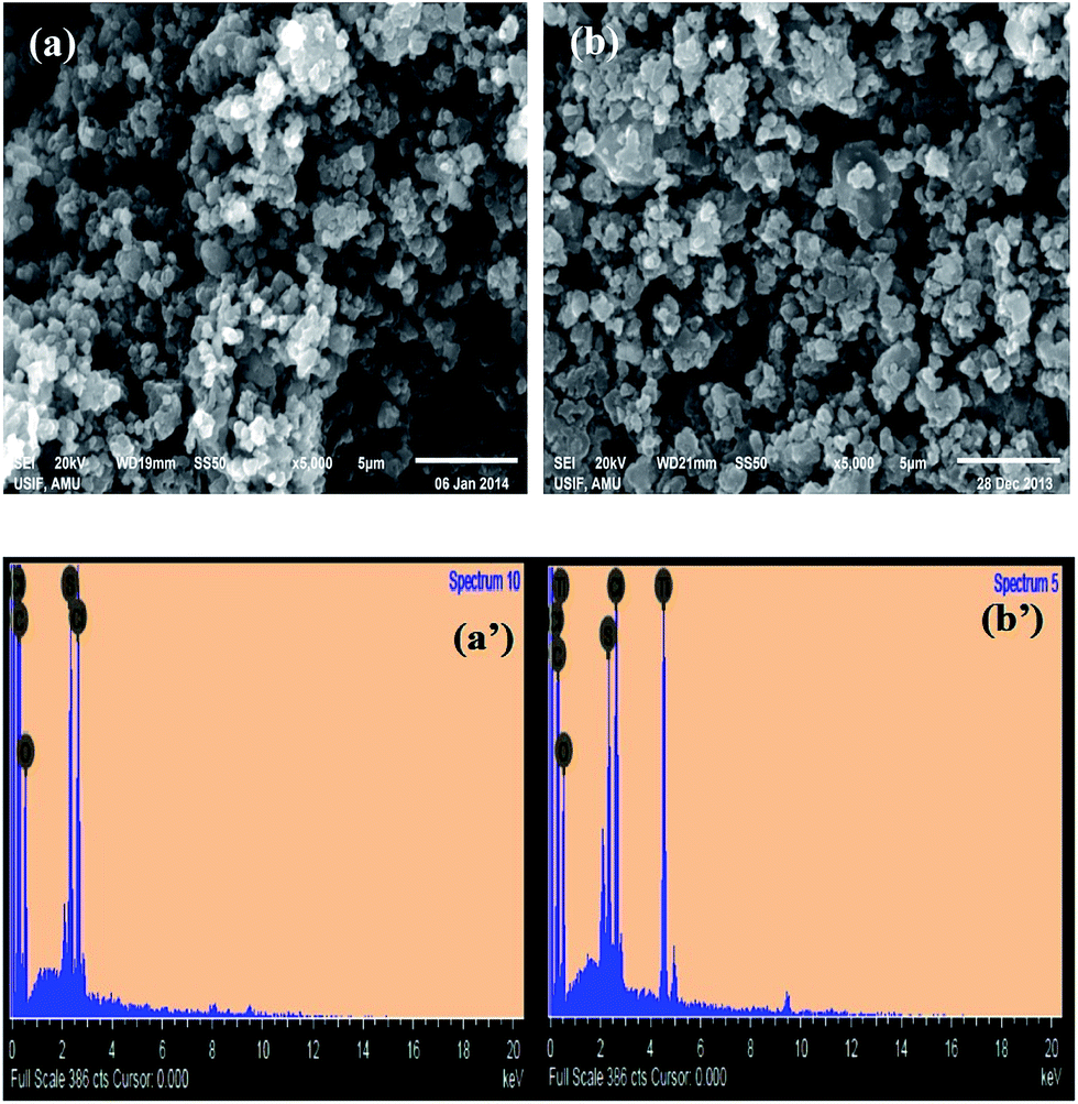
The SEM images of POT and POT–TiO2 nanocomposite are shown in Fig. 3a and b, respectively. Fig. 3a and b shows the granular morphology of POT and POT–TiO2 nanocomposite respectively. However the morphology of the nanocomposite (Fig. 3b) somewhat similar from that of the pristine POT. TiO2 NPs deposition is not clearly visible at the surface of POT, where it appears that the TiO2 nanoparticles are well inserted in the polymer (POT) matrix with homogeneous dispersion which has dense and globular structure suggesting that there is an ample evidence for the interaction of TiO2 nanoparticles with that of POT moiety which may be responsible for the change in the physical properties of the nanocomposite relative to pristine POT.
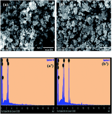 |
| | Fig. 3 SEM images of (a) POT (b) POT–TiO2 nanocomposite and their respective EDAX spectrum shows the elemental composition of synthesized (a′) POT (b′) POT–TiO2 nanocomposite. | |
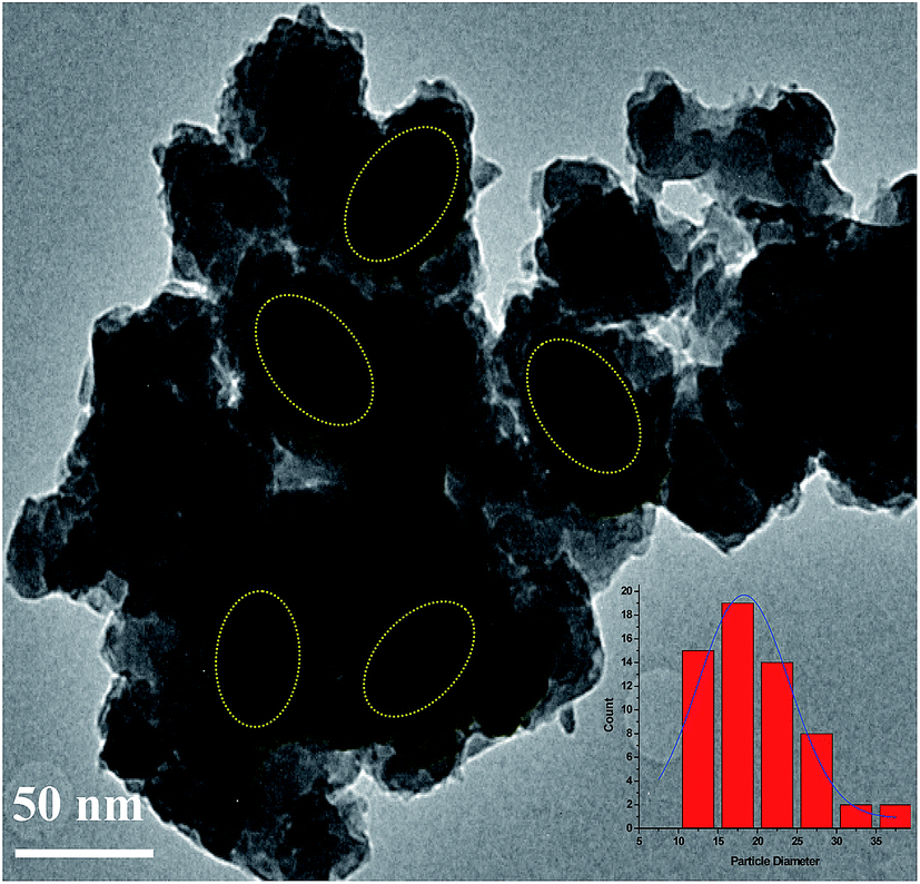
Fig. 4 shows the TEM image of POT–TiO2 nanocomposite with spherical morphology having an average particle size of ∼20 to 30 nm. The TiO2 nanoparticles are seen as dark spots dispersed in poly-o-toluidine matrix in the TEM image. For the further confirmation of spherical morphology we have taken the additional TEM image (shown as ESI Fig. S2†) which clearly shows TiO2 surface being coated with polymer which is not only exhibit strong interaction between POT and TiO2 but also enhanced the properties due to synergistic effect.
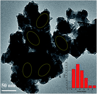 |
| | Fig. 4 TEM micrograph of POT–TiO2 nanocomposite. | |
3.3. X-ray diffraction analysis
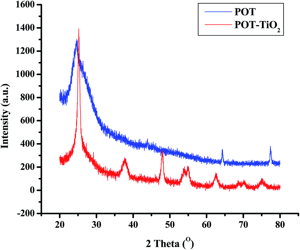
A comparative study of X-ray patterns of nanoparticles of POT and POT–TiO2 nanocomposite are shown in Fig. 5 reveals that there is a considerable inclusion of TiO2 nanoparticles in POT. However the comparative X-ray patterns of POT and POT–TiO2 nocomposites exhibit characteristic intense peaks observed at 2θ = 25, 38, 48, 55, and 64 etc. where the pronounced peak for POT is expected at 2θ = 25 appears in POT–TiO2 nocomposite suggesting the presence of POT. The average crystallite size of the POT and POT–TiO2 nanocomposite were calculated using the values of FWHM27,28 and were found to be in the range of 20–30 nm. The relative crystallite size of POT and POT–TiO2 has been found to be in the order of POT < POT–TiO2 indicating that TiO2 nanoparticles significantly influence the crystallite size of POT matrix in POT–TiO2 nanocomposite which may be possibly due to the polymerization of o-toluidine (OT) monomers adsorbed on the surface of TiO2 encapsulating TiO2 nanoparticles.
 |
| | Fig. 5 XRD diffractograms of POT and POT–TiO2 nanocomposite. | |
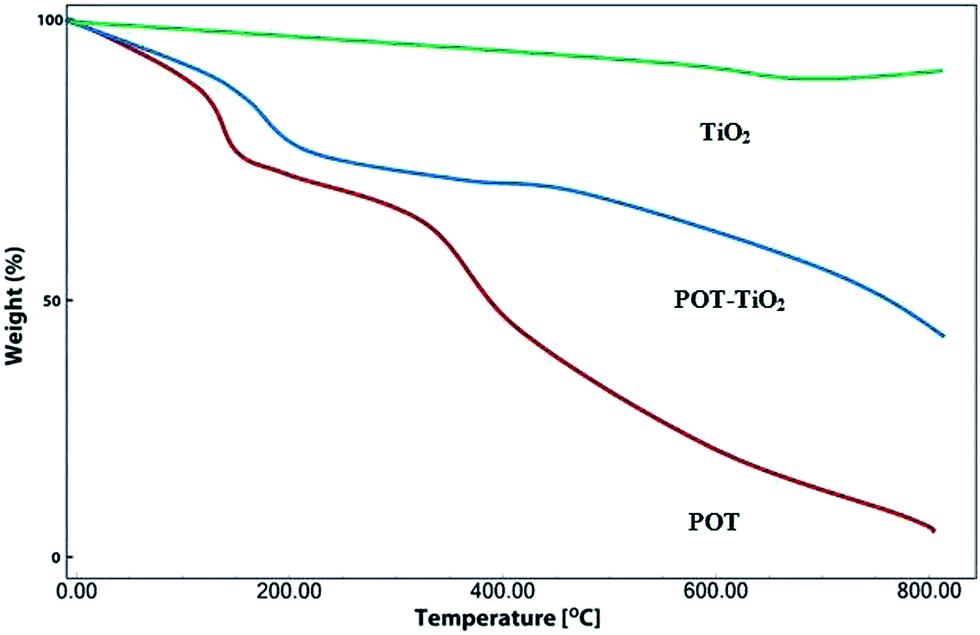
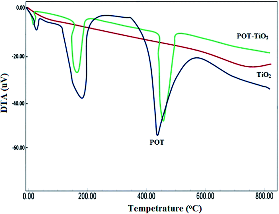
3.4. Thermogravimetric analysis (TGA) and differential thermal analysis (DTA)
The thermal stability of POT–TiO2 nanocomposite as compared with pristine TiO2 and POT was accomplished using thermogravimetric analysis (TGA), and the TGA and DTA curves of TiO2, POT and POT–TiO2 nanocomposite are shown in Fig. 6 and 7. POT showed two stages of weight loss: (1). Weight loss in the range of 100–200 °C, which is supported by DTA endothermic peak, can be attributed to the loss of physisorbed water molecules, HCl and other volatile matter/solvent, (2). Weight loss upto 380 °C along the second DTA endothermic peak can be assigned to polymer degradation (POT) leading to different degradation products such as pyridine based heterocycle, ammonia, aniline, N-phenyl-1, 4-benzenediamine, carbazole, methane, acetylene, p-phenylenediamine, N-phenylaniline, etc.29
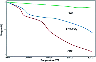 |
| | Fig. 6 TGA thermograms of TiO2, POT and POT–TiO2 nanocomposite. | |
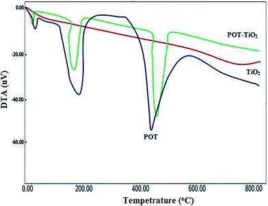 |
| | Fig. 7 DTA thermograms of TiO2, POT and POT–TiO2 nanocomposite. | |
The TGA of POT–TiO2 nanocomposite is somewhat similar to that of POT and the only noticeable difference is the high thermal stability of POT–TiO2 nanocomposite: for POT, major decomposition (about up to 50%) started at 380 °C, however POT–TiO2 nanocomposite showed an increased degradation temperature (450 °C) and in between about 30% weight was found. The total mass loss, up to 800 °C has been estimated to be ∼91%, 45.10% and 10% for the POT, POT–TiO2 nanocomposite and TiO2 nanoparticles, respectively. These evidences directly support the notion that the presence of TiO2 in the POT–TiO2 nanocomposite results in increased thermal stability of the composite material in comparison to pristine POT.29
3.5. UV-Visible spectroscopy
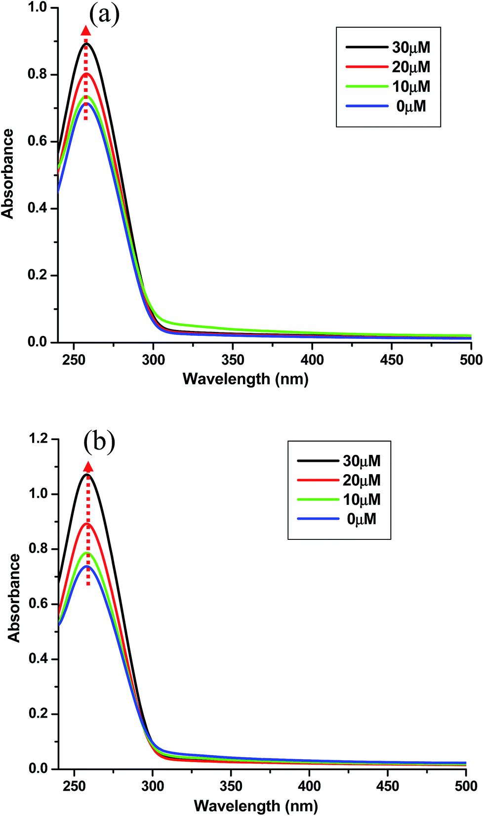
UV spectroscopy is generally employed for the determining binding mode of small molecules or drugs to DNA.30,31 Absorption spectra of POT (10 μM) and POT–TiO2 (10 μM) nanocomposite with respect to increasing concentration of ct-DNA (0–30 μM) is depicted in (Fig. 8a and b). As shown in the Fig. 8, when the POT and POT–TiO2 nanocomposite were titrated with increasing concentration of ct-DNA, both complexes presented a significant red shift, offering that there exists a strong interaction between the POT and POT–TiO2 nanocomposite with ct-DNA which is different from classical intercalation. Further it can be inferred from the (Fig. 8) that red shift is more prominent in case of POT–TiO2 nanocomposite than pristine POT which shows that POT–TiO2 nanocomposite binds more strongly to ct-DNA. Changes observed in spectra in presence of ct-DNA can be rationalized in terms of groove binding.32 Strong red shift was observed in case of POT–TiO2 nanocomposite suggesting that this posses higher propensity of DNA binding.
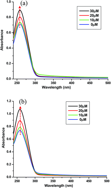 |
| | Fig. 8 Absorption spectra of (a) POT (10 μM) (b) POT–TiO2 (10 μM) in phosphate buffer on addition of ct-DNA. | |
3.6. Fluorescence studies
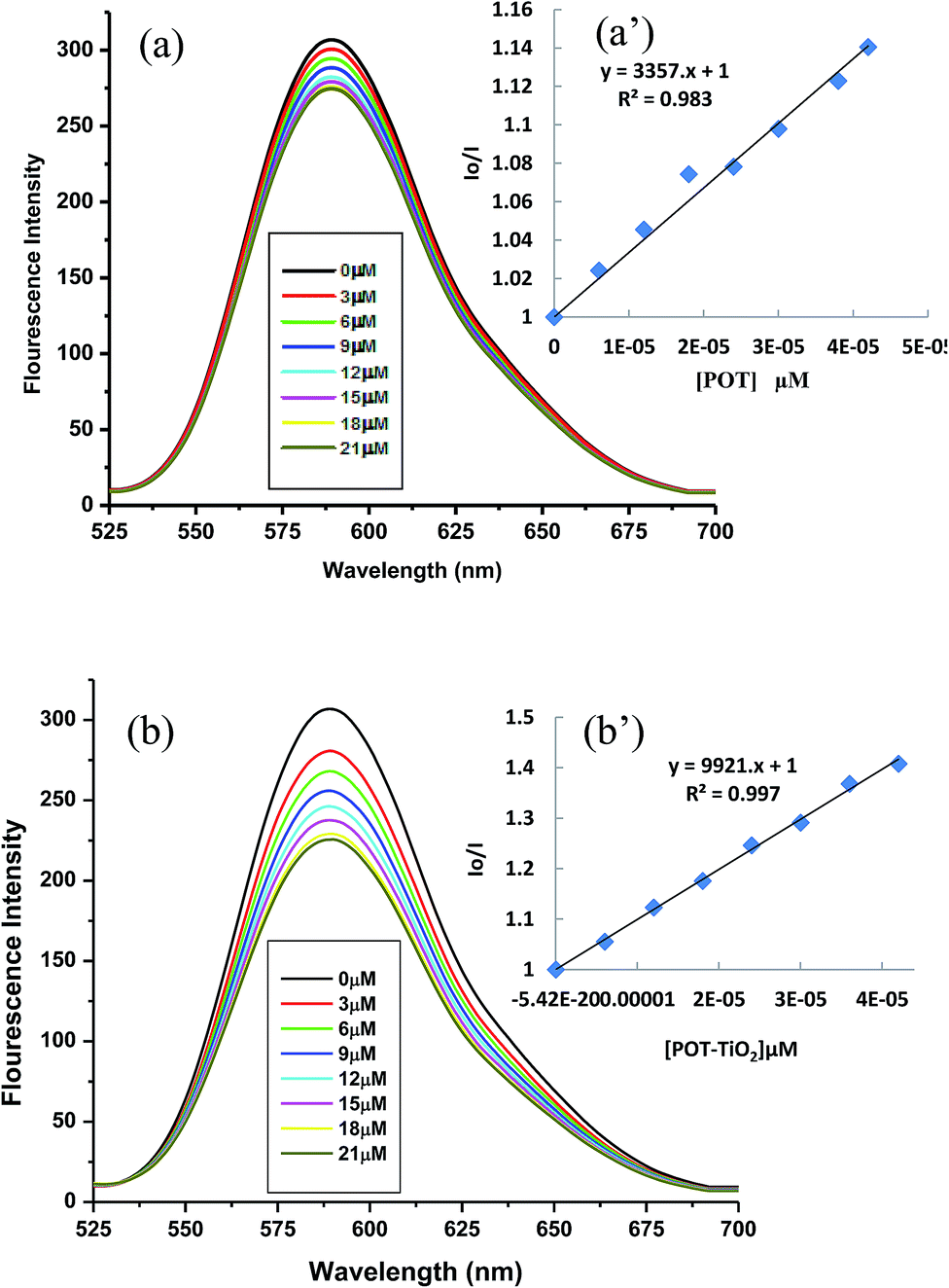
For monitoring the interaction between ct-DNA with POT and POT–TiO2 nanocomposite. We choose EB (Ethidium Bromide) as a fluorescent probe for DNA. EB has a weak fluorescence but in presence of DNA shows intense fluorescence on excitation at 480 nm. It is well known fact that the fluorescence of EB get quenched in presence of second molecule.33 In the present study we have studied the effect of POT and POT–TiO2 nanocomposite on the fluorescence emission spectra of EB bound to DNA as shown in (Fig. 9). It is clear from that the addition of POT and POT–TiO2 nanocomposite to a solution of EB bound to ct-DNA resulted in a decrease in fluorescence emission intensity of EB–DNA.
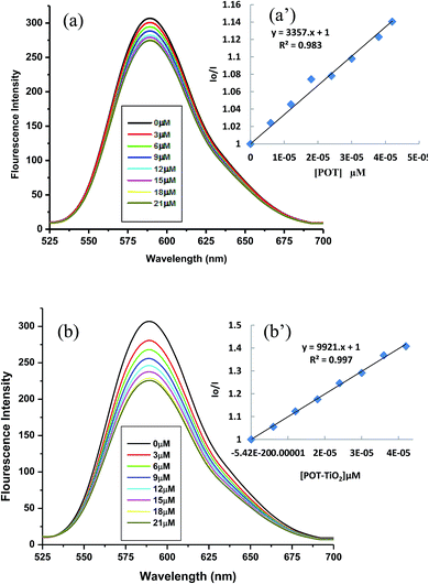 |
| | Fig. 9 Fluorescence quenching spectra of ct-DNA 10 μM in presence of increasing concentration (0–21 μM) with successive increment by 3 μM of (a) POT and (b) POT–TiO2. | |
But there is more decline fluorescence quenching in presence of POT–TiO2 nanocomposite as compared to POT (Fig. 9a and b). The fluorescence quenching is described by Stern–Volmer equation:
| Io/I = I + KSV[Q] = 1+ kqτo[Q] |
where
Io and
I are fluorescence intensity in the presence and absence of quencher respectively,
KSV is the Stern–Volmer constant,
τo is the lifetime of the fluorophore in the excited state and [Q] is the concentration of quencher. It can be inferred from the
Fig. 9a and b that POT–TiO
2 nanocomposite binds more strongly to DNA as compared to POT.
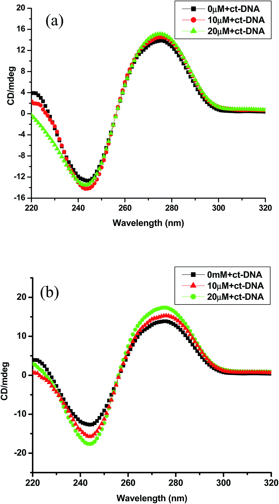
3.7. CD measurements
To further understand the DNA structural changes in presence of POT and POT–TiO2 nanocomposite and to reconfirm mode of interactions CD studies were performed. The positive absorption band at 274 nm and the negative one at 245 nm in CD spectrum are due to right handed halicity of ct-DNA and base stacking.34 The CD spectrum of ct-DNA after addition of POT are shown in (Fig. 10a) shows an increase in positive peak and decrease in negative peak upon addition. Similar CD spectral changes were observed in ct-DNA on addition of POT–TiO2 nanocomposite. Alterations in CD spectrum indicate strong conformational changes induced by POT and POT–TiO2 nanocomposite respectively. Further from (Fig. 10a and b) POT–TiO2 nanocomposite induced more prominent CD spectral changes as compared to pristine POT. This result suggests that CD spectra are closely correlated to the binding affinity. More declines in negative band might be due to unwinding of DNA helix upon interaction and transformed into other like conformation.
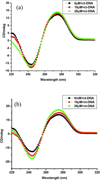 |
| | Fig. 10 CD spectra of (a) ct-DNA (100 μM) in presence of increasing concentration of POT (0, 10 and 20 μM) (b) ct-DNA in presence of increasing concentration of POT–TiO2 ((0, 10 and 20 μM)). | |
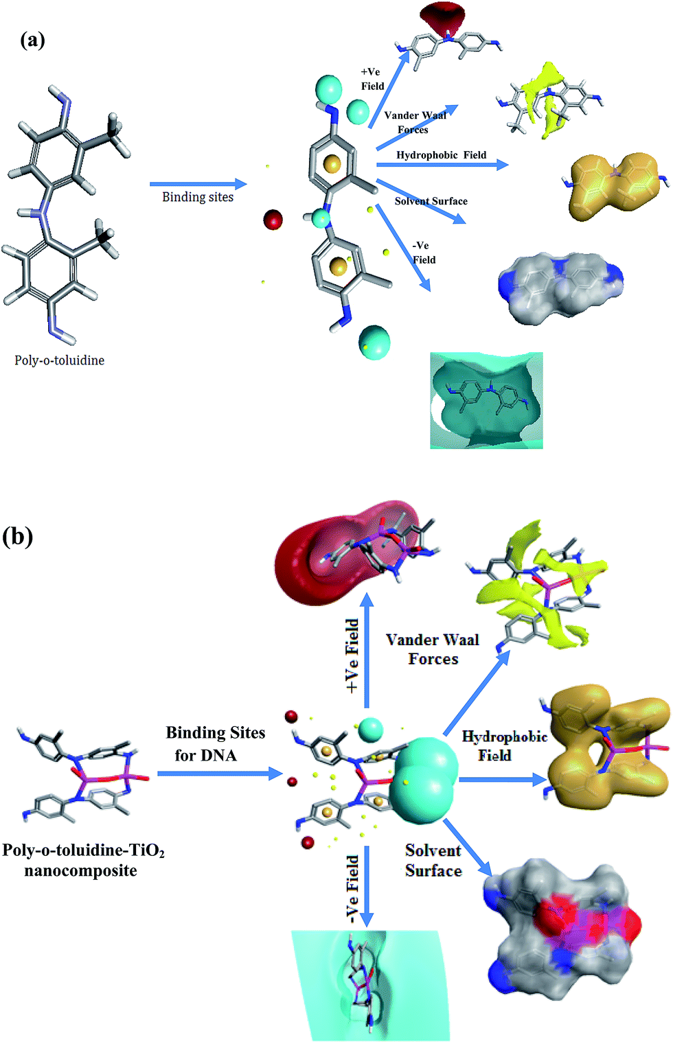
3.8. Field points of POT–TiO2 nanocomposite
Field points comprise of the electrostatic, van der Waals and hydrophobic potentials of the molecule and may be considered as extended information of pharmacophores, with the advantages that their position is directly calculated from the molecule's physical properties, and they have size/strength information associated with them and categorize the nature and capability of bonding with ligand–receptor interaction effects e.g. not all H-bond donors are treated the same: some make stronger bonds than others. The four field point patterns types are used to describe simultaneous performance of all the potential interactions that a Field points of POT–TiO2 nanocomposite in a specified conformation can make to a receptor as shown in Fig. 11.
 |
| | Fig. 11 Interpretation of a field point pattern of the expected (a) POT and (b) POT–TiO2 nanocomposite (the size of the point indicates the potential strength of the interaction); blue: negative field points (like to interact with positives/H-bond donors on a protein); red: positive field points (like to interact with negatives/H-bond acceptors on a protein); yellow: van der Waals surface field points (describing possible surface/vdW interactions) and gold/orange: hydrophobic field points (describe regions with high polarizability/hydrophobicity). (For interpretation of the references to color in this figure legend, the reader is referred to the web version of this article.) | |
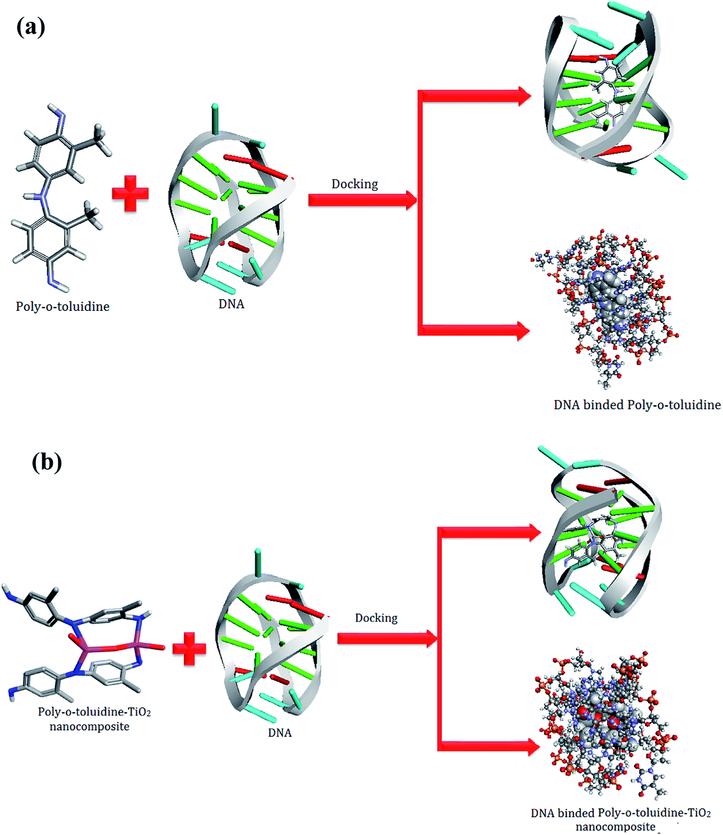
3.9. Molecular docking with DNA
Molecular docking is an application wherein molecular modeling techniques are used to predict how a protein interacts and alignments with drugs/ligands (POT and its POT–TiO2 nanocomposite). In the present study, to gain better understanding on the interactions between POT and its POT–TiO2 and G-quadruplex structure (PDB 143D) and to explore their binding mode, a docking study was performed using the CDOCKER protocol in Discovery Studio 4.0 Client (Dicovery Studio 4.0, Accelrys, Inc., San Diego, CA, USA). G-quadruplex human telomeric repeat d[AG3(TTAG3)3] (Protein Data Bank entry 143D) for docking were taken as a starting model and preferable binding sites of POT and its POT–TiO2 are respectively obtained to be 5′ G-quartet plane (with a diagonal loop) and groove 2 between the 3′-end and its residues. The energetically most favorable conformation of the docked pose (Fig. 12a and b) revealed that POT and POT–TiO2 fitted closely into the cavity of the targeted DNA in the minor groove within G–C rich region, as shown in Fig. 12. There are number of non bonding interaction such as van der Waals and hydrophobic contacts operating between polymer (POT) and its nanocomposite (POT–TiO2) with DNA bases which describe the stability of groove. The binding affinity of the docked POT and POT–TiO2 with DNA were found to be −5.13 & −8.14 kcal mol−1. It is clear from the energy difference that nanocomposite differ from conventional composite materials due to the exceptionally high surface to volume ratio of the reinforcing phase and/or its exceptionally high aspect ratio. Unique properties of nanocomposite bind with high affinity and selectivity to the binding active sites of DNA. The lowest energy was found in the compound POT–TiO2 with a binding energy of −8.14 kcal mol−1. Lower binding free energy indicates a more stable combination with DNA. Thus, we can conclude that the binding ability of POT–TiO2 nanocomposite with DNA is stronger than that of POT.
 |
| | Fig. 12 View of the simulated structure of (a) POT and (b) (POT–TiO2) nanocomposite bound to the binding site in the DNA bases structure formed from the sequence d[AG3(TTAG3)3 (pdb: 143D). All views were generated using the Discovery studio v4.0 Client. | |
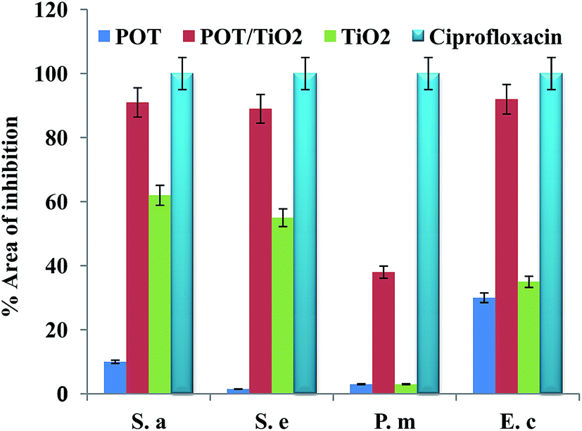
3.10. Antibacterial activity
TiO2, POT and its POT–TiO2 nanocomposite materials were evaluated for their in vitro antibacterial activities, both on gram negative (P. mirabilis, and E. coli) and gram positive (S. aureus, S. epidermidis) bacteria using disc diffusion method. The results were compared with the standard drug ciprofloxacin (Fig. 13) which suggest that the POT–TiO2 nanocomposite showed better antibacterial activity than the TiO2 and polymerized o-toluidine (Table 1). The enhanced antibacterial activity may be due to the presence of TiO2 in the POT–TiO2 nanocomposite which leads to the effect the size of the nanocomposite as antibacterial activity strongly depends on the size.35–38 It has been reported that the microorganism carry a negative charge and that a nano-metal oxide has a net positive charge, which might facilitate their interactions due to electromagnetic attraction, resulting in decreased bacterial load.39,40 Thus, it may be inferred that POT–TiO2 shows better antimicrobial activity than POT or drug alone due to presence of TiO2 in nanocomposite, which favors electromagnetic interactions.
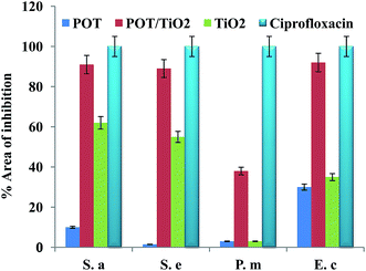 |
| | Fig. 13 Representing the comparative percent area of inhibition per μg of the compounds and the ciprofloxacin in case of gram positive and gram negative bacteria. | |
Table 1 Representing the inhibitory effects of microorganism (zone of inhibition in mm) and minimum inhibitory concentration, ciprofloxacin and DMSO were used as positive and negative control respectively
| Compounds |
Inhibitory effects of compounds on microorganism |
| Gram positive |
Gram negative |
| S. aureus |
S. epidermidis |
P. mirabilis |
E. coli |
| POT |
16.68 ± 0.010 |
10.30 ± 0.14 |
10.52 ± 0.11 |
17.34 ± 0.12 |
| POT–TiO2 |
19.47 ± 0.27 |
20.36 ± 0.76 |
16.54 ± 0.72 |
21.74 ± 0.21 |
| TiO2 |
13.43 ± 0.21 |
12.60 ± 0.10 |
12.63 ± 0.08 |
16.79 ± 0.71 |
| Ciprofloxacin |
21.46 ± 0.31 |
22.64 ± 0.54 |
22.24 ± 0.30 |
23.82 ± 0.47 |
| N.C |
— |
— |
— |
— |
| |
| Minimum inhibitory concentration (μg ml−1) |
| POT |
45 |
100 |
90 |
30 |
| POT–TiO2 |
6.20 |
3.122 |
12.0 |
12.3 |
| TiO2 |
50 |
100 |
100 |
25 |
| Ciprofloxacin |
6.25 |
3.125 |
6.25 |
12.5 |
Furthermore, POT–TiO2 nanocomposite materials may also denature bacterial enzymes by coordinating to the electron donating groups of these moieties. Additionally, TiO2 can also cause deformities in bacterial cell wall to render them leaky, hence resulting in bacterial death.11
4. Conclusion
In the present work a nanotechnological approach was adopted to design a nano tailored POT–TiO2 nanocomposite successfully synthesized in situ by using chemically oxidative polymerization technique. The results of TEM, SEM, XRD and FTIR studies revealed that the polymerization of POT has been achieved on the surface of the TiO2 nanoparticles indicating strong interaction between POT and TiO2 nanoparticles. The DNA binding studies of pristine POT and the POT–TiO2 nanocomposite have been compared using various biophysical methods. Molecular docking was performed to simulate the modes of interactions between the POT and its POT–TiO2 and DNA. The results demonstrate that their binding to DNA acts like groove binder which binds to the minor groove of DNA. It may be concluded from the binding free energies that the binding strength of the POT–TiO2 is stronger than that of the POT. The field points are also used to show the properties for a polymer and its nanocomposite to bind in a characteristic way into a specified active site. The comparative study of antimicrobial activities of POT, its POT–TiO2 nanocomposite and ciprofloxacin drug with different bacteria have also been under taken.
Acknowledgements
Prof. M. Shakir acknowledges the VPP of King Saud University. The author, M. S. Khan is thankful to University Grants Commission (UGC) for financial assistance. The authors, M. Shakir and M. S. Khan acknowledge the SAP-DRS-II and FIST programmes.
References
- A. Khan and U. Baig, Composites, Part B, 2014, 56, 862–868 CrossRef CAS PubMed.
- A. Khan and U. Baig, Sens. Actuators, B, 2013, 177, 1089–1097 CrossRef CAS PubMed.
- M. O. Ansari and F. Mohammad, Sens. Actuators, B, 2011, 157, 122–129 CrossRef CAS PubMed.
- A. Khan, U. Baig and M. Khalid, React. Funct. Polym., 2010, 70, 849–855 CrossRef CAS PubMed.
- A. Khan and U. Baig, J. Hazard. Mater., 2011, 186, 2037–2042 CrossRef CAS PubMed.
- A. Khan and U. Baig, J. Ind. Eng. Chem., 2013, 19, 1226–1236 CrossRef CAS PubMed.
- A. Khan and U. Baig, J. Ind. Eng. Chem., 2012, 18, 1937–1944 CrossRef CAS PubMed.
- A. Khan and U. Baig, Solid State Sci., 2012, 15, 47–52 CrossRef PubMed.
- M. O. Ansari, M. M. Khan, S. A. Ansari, I. Amal, J. Lee and M. H. Cho, Chem. Eng. J., 2014, 242, 155–161 CrossRef CAS PubMed.
- R. Kumar, M. O. Ansari and M. A. Barakat, Ind. Eng. Chem. Res., 2014, 53, 7167–7175 CrossRef CAS.
- M. Shakir, N. e. Iram, M. S. Khan, S. I. Al-Resayes, A. A. Khan and U. Baig, Ind. Eng. Chem. Res., 2014, 53, 8035–8044 CrossRef CAS.
- V. Eskizeybek, F. Sarı, H. Gülce, A. Gülce and A. Avci, Appl. Catal., B, 2012, 119, 197–206 CrossRef PubMed.
- H. Gülce, V. Eskizeybek, B. Haspulat, F. Sarı, A. Gülce and A. Avci, Ind. Eng. Chem. Res., 2013, 52, 10924–10934 CrossRef.
- M. Shahadat, S. A. Nabi, R. Bushra, A. S. Raeissi, K. Umar and M. O. Ansari, RSC Adv., 2012, 2, 7207–7220 RSC.
- F. N. Crespilho, R. M. Iost, S. A. Travain, O. N. Oliveira and V. Zucolotto, Biosens. Bioelectron., 2009, 24, 3073–3077 CrossRef CAS PubMed.
- H. An and B. Jin, Biotechnol. Adv., 2012, 30, 1721–1732 CrossRef CAS PubMed.
- K. Saleem, W. A. Wani, A. Haque, M. N. Lone, M. F. Hsies, M. A. Jairajpuri and I. Ali, Future Med. Chem., 2013, 5, 135–146 CrossRef CAS PubMed.
- C. M. R. Low and J. G. Vinter, J. Med. Chem., 2008, 51, 565–573 CrossRef CAS PubMed.
- S. Ahmad, U. Riaz, M. Kashif and M. S. Khan, J. Inorg. Organomet. Polym., 2012, 22, 662–670 CrossRef CAS.
- H. Cai, X. An, J. Cui, J. Li, S. Wen, K. Li, M. Shen, L. Zheng, G. Zhang and X. Shi, ACS Appl. Mater. Interfaces, 2013, 5, 1722–1731 CAS.
- Y. Wang and D. J. Patel, Structure, 1993, 1, 263–282 CrossRef CAS.
- Discovery Studio v3.5 client Copyright @2005-12 Accelrys software Inc.
- J. M. Yang, iGEMDOCK, Bioxchem., 2008.
- C. V. Kumar and E. H. Asuncion, J. Am. Chem. Soc., 1993, 115, 8547–8553 CrossRef CAS.
- K. M. Zaidan, R. A. Talib, M. A. Rahma and F. H. Khaleel, Chem. Sin., 2012, 3, 841–848 CAS.
- T. Anwer, M. O. Ansari and F. Mohammad, J. Ind. Eng. Chem., 2013, 19, 1653–1658 CrossRef CAS PubMed.
- M. J. Meziani, P. Liu, P. Pathak, J. Lin, S. K. Vajandar, L. F. Allard and Y. P. Sun, Ind. Eng. Chem. Res., 2006, 45, 1539 CrossRef CAS.
- O. Rahman, S. C. Mohapatra and S. Ahmad, Mater. Chem. Phys., 2012, 132, 196–202 CrossRef CAS PubMed.
- M. O. Ansari and F. Mohammad, J. Appl. Polym. Sci., 2012, 124, 4433–4442 CAS.
- S. U. Rehman, Z. Yaseen, M. A. Husain, T. Sarwar, H. M. Ishqi and M. Tabish, PLoS One, 2014, 9, 1–11 Search PubMed.
- A. E. Radi, A. Eissa and H. M. Nassef, J. Electroanal. Chem., 2014, 717, 24–28 CrossRef PubMed.
- Z. Q. Liu, Y. T. Li, Z. Y. Wu and S. F. Zhang, Inorg. Chim. Acta, 2009, 362, 71–77 CrossRef CAS PubMed.
- M. Sunita, B. Anupama, B. Umesh and C. G. Kumari, Arabian J. Chem., 2014 DOI:10.1016/j.arabjc.2014.01.017.
- W. Li, Y. Y. Ji, J. W. Wang and Y. M. Zhu, DNA Cell Biol., 2012, 31, 1046–1053 CrossRef CAS PubMed.
- H. Zhang and G. Chen, Environ. Sci. Technol., 2009, 43, 2905–2910 CrossRef CAS.
- P. Boomi and H. G. Prabu, Colloids Surf., A, 2013, 429, 51–59 CrossRef CAS PubMed.
- S. Honary, K. Ghajar, P. Khazaeli and P. Shalchian, Trop. J. Pharm. Res., 2011, 10, 69–74 CAS.
- P. Boomi, H. G. Prabu and J. Mathiyarasu, Eur. J. Med. Chem., 2014, 72, 18–25 CrossRef CAS PubMed.
- A. Thomas1, M. S. Raj and J. Venkataramana, Int. J. Bioassays, 2014, 3, 3106–3110 Search PubMed.
- M. Haghi, M. Hekmatafshar, M. B. Janipour, S. S. Gholizadeh, M. K. Faraz, F. Sayyadifar and M. Ghaedi, Int. J. Adv. Biotechnol. Res., 2012, 3, 621–624 CAS.
Footnote |
| † Electronic supplementary information (ESI) available: Details of preparation of POT and POT–TiO2 nanocomposite and the TEM micrograph represents the formation of PCz–TiO2 nanocomposite and also showing the polymerization of carbazole on the surface of TiO2 nanoparticles. See DOI: 10.1039/c4ra05173d |
|
| This journal is © The Royal Society of Chemistry 2014 |
Click here to see how this site uses Cookies. View our privacy policy here.