Synthesis of copper nanoparticles by a T-shaped microfluidic device

Lei Xu ab, Jinhui Peng *a, C. Srinivasakannan c, Libo Zhang a, Di Zhang b, Chenhui Liu a, Shixing Wang a and Amy Q. Shen *b
aNational Local Joint Laboratory of Engineering Application of Microwave Energy and Equipment Technology, Faculty of Metallurgical and Energy Engineering, Kunming University of Science and Technology, Kunming 650093, PR China. E-mail: xulei_kmust@aliyun.com; Fax: +86 871 65138997; Tel: +86 13759104608
bMechanical Engineering, University of Washington, Seattle, Washington 98195, USA. E-mail: amyshen@uw.edu; Fax: +1-206-221-0372; Tel: +1-206-685-8047
cChemical Engineering Program, The petroleum Institute, P.O. Box 253, Abu Dhabi, United Arab Emirates

Received 7th May 2014 , Accepted 28th May 2014

First published on 29th May 2014


Abstract

The copper nanoparticles were prepared by reduction of metal salt solutions with sodium borohydride in a T-shaped microfluidic device at room temperature. The influence of flow rates on copper particle diameter, morphology, size distribution, and elemental compositions has been investigated. Experimental results demonstrated that copper nanoparticles were uniform in size distribution, without being oxidized. With the increase in fluid flow rate the copper nanoparticles mean diameter increased, and the surface plasmon resonance absorptions of copper nanoparticles exhibited slight blue-shifting.

Introduction

In recent years, microreactors have gained much attention in nanoparticle synthesis due to the advantage of precise control of reaction and mixing conditions. The benefits of microreactors are high-surface-area-to-volume ratio, tunable inner-wall properties, flow-orientation and flexible-structure design of the micromixers.1–6 In addition, the key advantages of micro-reaction technology are diffusive exchange of heat and mass within small length scales. These features have enabled the use of microreactors to improve the reaction efficiency and control the synthesis of nanomaterials.1,4–12

Metal nanoparticles have been widely used in catalysis, optoelectronics, photovoltaic technology, information storage, environmental technology, and biosensors, to name a few. The need for low-cost, scalable, and dispersible nanomaterials drives new research in the field of nanocrystal synthesis.13,14 The preparation of Cu nanoparticles has become an intensive area of scientific research as Cu nanoparticles exhibit excellent physical and chemical properties such as high electrical conductivity and chemical activity. Cheaper Cu have been considered possible replacements for Ag and Au particles in some potential applications such as high electrical conductivity and chemical activity.1,12–16 Existing chemical procedures to synthesize Cu nanoparticles include, radiation, thermal reduction, microemulsion, sonochemical reduction, vacuum vapor deposition, metal vapor synthesis, laser ablation, and aqueous reduction methods.13–20 Among these methods, aqueous reduction method is most widely employed because of its simple operation procedure, high yield and quality, limited equipment requirements and ease of control.15 Liu et al. reported preparation of Cu nanoparticles with NaBH4 by aqueous reduction method.15 Song et al. described controlled growth of Cu nanoparticles by a tubular microfluidic reactor.1

The processing conditions to synthesize nanoparticles are of particular importance for the control of particle size, particle shape, aggregation and composition of Cu nanoparticles. The rate of nucleation and the rate of particle growth depends in different ways on the local concentrations of educts.8 In the present work, Cu nanoparticles were prepared by aqueous reduction method, using NaBH4 as reducing agent in T-shaped microfluidic chip.

Experimental method

Materials

Copper(II) sulfate pentahydrate (CuSO4·5H2O, purity ≥ 98%), sodium borohydride(NaBH4, purity ≥ 99%), polyvinylpyrrolidone(PVP, average molecular weight 360[thin space (1/6-em)]000), ammonium hydroxide solution (NH3·H2O, 28.0–30.0%) and sodium hydroxide(NaOH, 99%) were purchased from Sigma-Aldrich (St. Louis, MO, USA). Sylgard 184 silicone elastomer kits including poly (polydimethylsiloxane, PDMS) and a curing agent were purchased from Dow Corning Co. (Midland, MI).

Fabrication of chip-based microfluidic reactor

The PDMS microfluidic devices were fabricated by a soft lithography technique as described in literature.10,21 The PDMS prepolymer and the curing agent are mixed in a 10[thin space (1/6-em)]:[thin space (1/6-em)]1 ratio (v/v), and poured onto a silicon wafer patterned with SU-8 photoresist. After degassing under vacuum in a desiccator for an hour, the PDMS material was baked for 2 h at 65 °C in an oven. The PDMS replicas and the glass slide were then bonded after oxygen plasma treatment and placed in an oven (65 °C) for 2 days before experiments.

Synthesis of copper nanoparticles

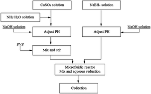
The flowchart of the experimental process is shown in Fig. 1. Prior to carrying out the experiments, 0.2 mol L−1 CuSO4 solution and 0.4 mol L−1 NaBH4 solution were prepared, and argon gas was bubbled through both solutions for 30 min. A certain proportion of ammonium hydroxide solution was added to the CuSO4 solutions complexant, which turned the color of solutions from blue to dark blue. Then the pH of CuSO4 solutions was adjusted to 12 by the addition of NaOH solution. The PVP at a concentration of 3.2 g L−1 was added to the CuSO4 complex solution as a dispersant.
image file: c4ra04247f-f1.tif
Fig. 1 Flowchart of Cu nanoparticles preparation processes by aqueous reduction with sodium borohydride.

The microfluidics chip used to prepare Cu nanoparticles is shown in Fig. 2. T-shaped microchannel was used to introduce two aqueous solutions flowing into the microchannel. The microfluidic synthesis was performed at room temperature (25 ± 2 °C). This microfluidic device was placed on an inverted microscope (Leica DM IRB) to track the synthesis of Cu nanoparticles. The complex solution CuSO4 and the aqueous mixture containing NaBH4 were pumped to the microchannel using digitally controlled syringe pumps (PHD 2000 Infusion, Harvard Apparatus, USA). The experiments were conducted at different flow rates covering the range 10 mL h−1 to 30 mL h−1.


image file: c4ra04247f-f2.tif
Fig. 2 Schematic of the synthesis processes of the copper nanoparticles by T-shaped microfluidic chip at room temperature. The length, width and height of the channel are 10 mm, 200 μm and 30 μm, respectively.

The general chemical reaction to produce Cu nanoparticles is based on the following equation.15

 
4Cu2+ + BH4 + 8OH = 4Cu + B(OH)4 + 4H2O(1)

When NH3·H2O is adopted as complexant, the reduction reaction can be represented by the following equations,

 
Cu2+ + 4NH3·H2O = Cu(NH3)2+4 + 4H2O(2)
 
4Cu(NH3)2+4 + BH4 + 8OH = 4Cu + B(OH)4 + 16NH3 + 4H2O(3)

In theory, the stoichiometric ratio of Cu ions to NaBH4 is 4[thin space (1/6-em)]:[thin space (1/6-em)]1. In addition, Liu et al., have reported a reduction in the average size of the Cu nanoparticles with increase in NaBH4 concentration.15 In general the reducing agents are added far in excess of stoichiometric requirement to promote the reaction sufficiently.

Material characterizations

The Cu nanoparticles size and morphology are characterized by using transmission electron microscopy (TEM, 2100F, 200 kV, JEOL). For the TEM investigations the material was deposited by drying its suspension on a copper-grid-supported, perforated, transparent carbon foil. Elemental compositions of the copper nanoparticles were obtained by using energy-dispersive X-ray spectrometer (EDS), operated at 200 kV. The UV-vis spectrometry was used to verify the chemical composition of nanoparticles and the average size was estimated using a spectrometer (UV-2450, SHIMADZU).

Results and discussion

The influence of flow rates in the microfluidic flow on final copper particle diameter, morphology, size distribution, and elemental compositions was examined. Fig. 3 shows the size, morphology and elemental compositions of the copper nanoparticles at flow rate 10 mL h−1. From Fig. 3(a) and (b), copper nanoparticles are spherical, uniform particle size, with good dispersion. The particle size distribution shows the mean diameter of 8.95 nm (Fig. 3(c)). Fig. 3(d) presents the energy dispersive spectrometer which indicates the absence of oxidation in the process of copper nanoparticles synthesis, proving the effectiveness of the PVP dispersant as an antioxidant.
image file: c4ra04247f-f3.tif
Fig. 3 The TEM image (A and B) and the particle size distribution (C) and the EDS spectrum (D) of the copper nanoparticles prepared by aqueous reduction with sodium borohydride in the T-shaped microfluidic chip at the flow rate of 10 mL h−1.

Fig. 4 shows the size and morphology of the copper nanoparticles at a flow rate of 20 mL h−1 and 30 mL h−1. The mean particle diameter of copper nanoparticles was estimated to be 9.18 nm and 14.15 nm, respectively. An increase in the flow rate clearly yields an increase in the mean particle diameter. Wei et al., have reported synthesis and thermal conductivity of microfluidic copper nanofluids, cupric-sulfate (CuSO4) reduced by hydrazine-hydrate (N2H4). Their results showed an increase in mean particle diameter with an increase in the flow rate, except for the case of N2H4 molar concentration 0.02 M,12 which are in agreement with the results of the present work. Liu et al., have reported preparation of very fine Cu nanoparticles of 37 nm, at the following conditions: concentrations of Cu2+ and NaBH4 being 0.2 and 0.4 mo1 L−1 respectively, the dripping rate of 50 mL min−1, gelatin concentration of 1%, PH at 12 and solution temperature at 313 K.15 In the present work, the mean particle diameter as low as 9 nm could be achieved utilizing a T-shaped microfluidic chip.


image file: c4ra04247f-f4.tif
Fig. 4 The TEM image (A and B) and the particle size distribution (A′ and B′) of the copper nanoparticles prepared by aqueous reduction with sodium borohydride in the T-shaped microfluidic chip at the flow rate of 20 mL h−1 and 30 mL h−1, respectively.

Comparing Fig. 3 and 4, the effect of flow rate on the appearance of copper nanoparticles prepared by microfluidic chips can be demonstrated. The particle size distribution as well as the mean particle size at a flow rate of 20 mL h−1 compare closely with the flow rate of 10 mL h−1. However, at the flow rate of 30 mL h−1, the particle size distribution is skewed to the right with the mean particle diameter much higher than the lower flow rates. The proportion of particles in the lower size range is significantly higher than the particles at the higher size range. The non uniformity in the size is evident from the particle size distribution.

Song et al., have reported the growth of nearly monodispersed Cu nanoparticles of 135.6 ± 11.4 nm in a tubular microfluidic reactor. Such a large particle size was enabled through continued controlled growth of the initially formed Cu nanoparticle seeds in a tubular microfluidic reactor.1 In the present work, Cu nanoparticles were prepared using aqueous reduction which include four distinct stages: the formation of a supersaturated solid solution, nucleation, growth and aggregation, as proposed by LaMer and Dinegar.1,22 The solute consisting of ions are formed by chemical reactions. When the solute concentration attains a critical concentration, the formation of spontaneous nuclei occurs, which reduces solute concentration, halts further nucleation and freezes the number of nuclei that are formed. The nucleation stage is followed by the growth of the particles. The growth of particles from the limited nuclei proceeds until all of the solute has been consumed. Therefore, in order to obtain a narrow particle size distribution, the nucleation time should be minimized.

In the T-shaped microfluidic chip, a basic characteristic of the micro-scale fluid flow is laminar (Fig. 5). The reaction is mass transfer controlled with the rate of diffusion of ions to the interphase governing the rate of reaction. Therefore, when the reaction proceeded to 60 s, the layer of reaction to be darker than the reaction proceeded to 30 seconds. The diffusion of ions to the interphase is rather slow in laminar flow and hence at faster flow rates the diffusion of ions to the interphase is limited, which results in formation of fewer Cu nanoparticles nuclei. The formed nuclei continue to grow resulting in relatively larger and non uniform particle size. In contrast, at low flow rates the diffusion of Cu ions to the interphase is relatively larger resulting in higher nuclei formation. The continued growth of solute over the larger number of nuclei results in smaller and more uniform size of the Cu nanoparticles.


image file: c4ra04247f-f5.tif
Fig. 5 Optical microscope image of copper nanoparticles formed at different times in the T-shaped microfluidic chip. Image (A) is the reaction proceeded to 30 s, and Image (B) is the reaction proceeded to 60 s.

Variations of the size, shape and elemental compositions of Cu nanoparticles prepared by microfluidic chip at different flow rate definitely affect their localized surface plasmon resonance absorption characterized by the UV-vis spectroscopy. As shown in Fig. 6, with the increase in fluid flow rate, the copper nanoparticles diameter increases and their surface plasmon resonance absorptions exhibit slight blue-shifting, as shown by the peak at 575 nm for the 8.95 nm Cu nanoparticles, the peak at 567 nm for the 9.18 nm Cu nanoparticles and the peak at 564 nm for the 14.15 nm Cu nanoparticles respectively. Many authors have associated the blue-shift of the surface plasmon resonance of the metallic nanoparticles with their decreasing size,13,23,24 which may not be the case always. Yang et al. showed contrary data for spherical Cu nanoparticles,25 which agrees with the results of the present work, supported by the TEM images. This could be due to the combined effects of variations of their size, size distribution, shape, aggregation, surface roughness and crystallinity, and the surface-coated surfactant.19,26–28


image file: c4ra04247f-f6.tif
Fig. 6 UV-vis absorption of Cu nanoparticles prepared by the flow rate of 10 mL h−1, 20 mL h−1 and 30 mL h−1.

Conclusions

In summary, copper nanoparticles can be prepared by reduction of metal salt solutions with sodium borohydride in the T-shaped microfluidic chip at room temperature. PVP as a dispersant has better dispersion and antioxidant effects. The prepared copper nanoparticles were uniform in size distribution without being oxidized. The mean particle diameter increased with increase in the fluid flow rate, with the maximum mean of 14.15 nm at a fluid flow rate of 30 mL h−1, however with a non uniform particle size distribution (distribution skewed to the right). At low flow rates the particle size distribution was found to be normal, however with a smaller mean particle diameter. An increase in the particle size could be achieved with increase in the flow rate. Additionally, with increase in particle size the surface plasmon resonance absorptions exhibited slight blue-shifting.

Acknowledgements

This work was financially supported by the National Natural Science Foundation of China (Grant no. 51204081 and U1302271), and by China Scholarship Council (no. 2011853521), and by Yunnan Provincial Science and Technology Innovation Talents scheme – Technological Leading Talent of China (no. 2013HA002), and by Applied Basic Research Project of Yunnan Province of China (Grant no. 2013FZ008), and by Yunnan Provincial Department of Education Research Fund of China (Grant no. 2013Z118).

Notes and references

  1. Y. Song, R. Li, Q. Sun and P. Jin, Chem. Eng. J., 2011, 168, 477–484 CrossRef CAS PubMed.
  2. T. Sounart, P. Safier, J. Voigt, J. Hoyt, D. Tallant, C. Matzke and T. Michalske, Lab Chip, 2007, 7, 908–915 RSC.
  3. A. J. Demello, Nature, 2006, 442, 394–402 CrossRef CAS PubMed.
  4. B. Zhao, J. S. Moore and D. J. Beebe, Science, 2001, 291, 1023–1026 CrossRef CAS PubMed.
  5. S. He, T. Kohira, M. Uehara, T. Kitamura, H. Nakamura, M. Miyazaki and H. Maeda, Chem. Lett., 2005, 34, 748–749 CrossRef CAS.
  6. J. I. Park, A. Saffari, S. Kumar, A. Günther and E. Kumacheva, Annu. Rev. Mater. Res., 2010, 40, 415–443 CrossRef CAS.
  7. C.-X. Zhao, L. He, S. Z. Qiao and A. P. Middelberg, Chem. Eng. Sci., 2011, 66, 1463–1479 CrossRef CAS PubMed.
  8. J. Wagner, T. Tshikhudo and J. Koehler, Chem. Eng. J., 2008, 135, S104–S109 CrossRef CAS PubMed.
  9. J. Parisi, L. Su and Y. Lei, Lab Chip, 2013, 13, 1501–1508 RSC.
  10. M. A. Ali, P. R. Solanki, M. K. Patel, H. Dhayani, V. V. Agrawal, R. John and B. D. Malhotra, Nanoscale, 2013, 5, 2883–2891 RSC.
  11. Y. Song, E. Doomes, J. Prindle, R. Tittsworth, J. Hormes and C. S. R. Kumar, J. Phys. Chem. B, 2005, 109, 9330–9338 CrossRef CAS PubMed.
  12. X. Wei and L. Wang, Particuology, 2010, 8, 262–271 CrossRef CAS PubMed.
  13. K. Tokarek, J. L. Hueso, P. Kuśtrowski, G. Stochel and A. Kyzioł, Eur. J. Inorg. Chem., 2013, 4940–4947 CAS.
  14. P. Lignier, R. Bellabarba and R. P. Tooze, Chem. Soc. Rev., 2012, 41, 1708–1720 RSC.
  15. L. Qing-ming, Z. De-bi, Y. Yamamoto, R. Ichino and M. Okido, Trans. Nonferrous Met. Soc. China, 2012, 22, 117–123 CrossRef.
  16. A. M. Raspolli Galletti, C. Antonetti, M. Marracci, F. Piccinelli and B. Tellini, Appl. Surf. Sci., 2013, 280, 610–618 CrossRef CAS PubMed.
  17. S. Joshi, S. Patil, V. Iyer and S. Mahumuni, Nanostruct. Mater., 1998, 10, 1135–1144 CrossRef CAS.
  18. N. A. Dhas, C. P. Raj and A. Gedanken, Chem. Mater., 1998, 10, 1446–1452 CrossRef CAS.
  19. W. Yu, H. Xie, L. Chen, Y. Li and C. Zhang, Nanoscale Res. Lett., 2009, 4, 465–470 CrossRef CAS PubMed.
  20. B. K. Park, S. Jeong, D. Kim, J. Moon, S. Lim and J. S. Kim, J. Colloid Interface Sci., 2007, 311, 417–424 CrossRef CAS PubMed.
  21. Q. Wang, D. Zhang, X. Yang, H. Xu, A. Q. Shen and Y. Yang, Green Chem., 2013, 15, 2222–2229 RSC.
  22. V. K. LaMer and R. H. Dinegar, J. Am. Chem. Soc., 1950, 72, 4847–4854 CrossRef CAS.
  23. T. M. D. Dang, T. T. T. Le, E. Fribourg-Blanc and M. C. Dang, Adv. Nat. Sci.: Nanosci. Nanotechnol., 2011, 2, 015009 CrossRef.
  24. A. M. Schwartzberg, T. Y. Olson, C. E. Talley and J. Z. Zhang, J. Phys. Chem. B, 2006, 110, 19935–19944 CrossRef CAS PubMed.
  25. L. I. Hung, C. K. Tsung, W. Huang and P. Yang, Adv. Mater., 2010, 22, 1910–1914 CrossRef CAS PubMed.
  26. A. Moores and F. Goettmann, New J. Chem., 2006, 30, 1121–1132 RSC.
  27. A. Braundmeier Jr and E. Arakawa, J. Phys. Chem. Solids, 1974, 35, 517–520 CrossRef.
  28. Y. Song and H. E. Elsayed-Ali, Appl. Surf. Sci., 2010, 256, 5961–5967 CrossRef CAS PubMed.

This journal is © The Royal Society of Chemistry 2014
Click here to see how this site uses Cookies. View our privacy policy here.