Cationic imidazolium polymer monoliths for efficient solvent exchange, activation and fluorination on a continuous flow system†
Rehana Ismailab,
Jonathan Irribarenab,
Muhammad Rashed Javedab,
Ariella Machnessab,
R. Michael van Damab and
Pei Yuin Keng*ab
aDepartment of Molecular and Medical Pharmacology, University of California, Los Angeles, Los Angeles, CA 90095, USA. E-mail: pkeng@mednet.ucla.edu
bCrump Institute for Molecular Imaging, David Geffen School of Medicine, University of California, Los Angeles, Los Angeles, CA 90095, USA
First published on 29th May 2014
Abstract
Polystyrene-imidazolium (PS-Im+Cl−) monolith was synthesized within a flow-through microfluidic chip and Teflon tubing for activating [18F]fluoride ions. The [18F]fluoride ions were trapped on the PS-Im+ monolith and were subsequently released with various phase-transfer catalysts (PTC) and carbonate or bicarbonate bases in microliter volumes of organic solvents containing 0.5% of water. The activated [18F]fluoride complex released from the PS-Im+ monolith was used to fluorinate various known PET probe precursors with diverse reactivity in a subsequent flow-through microfluidic chip without performing additional azeotropic distillation. The fluorination yields under the optimized condition for the protected [18F]FDG, protected [18F]FLT, 4-[18F]fluoroethylbenzoate, and [18F]fallypride were 93%, 96%, 77% and 73%, respectively. This method, utilizing the PS-Im+ monolith on a flow through microfluidic platform, enables the entire fluorine-18 radiochemistry to be performed on a flow-through microfluidic device within a shorter synthesis time and with fluorination efficiency that is comparable to or higher than conventional means.
Introduction
Flow-through microfluidic devices have been utilized in a myriad of chemical syntheses, with enhanced reaction kinetics, product purity and selectivity. The small reaction volume, intrinsic to microfluidic devices, allows for fast heat and mass transfer, which is difficult to achieve in conventional macroscale chemical synthesis.1 In addition, microfluidic devices allow for the reduction in reagent consumption and waste production. The use of small quantities of materials enables the use of hazardous and sensitive substances in a safer environment. In medical diagnostics, specifically in the synthesis of short-lived (F-18 t1/2 = 109 min) radiotracers for positron emission tomography (PET), the small dimensions of microfluidics have an added advantage of dramatically reducing the amount of radiation shielding needed to protect the operator.2–4PET is a highly sensitive and non-invasive real-time visualization technique for biochemical and physiological processes in living organism.5 Recently, there has been much progress in developing microfluidic radiosynthesizers to produce PET probes. The compact size of a microfluidic radiosynthesizer could allow researchers to produce desirable PET tracers themselves at the imaging center, with the potential to increase the availability and diversity of the number of probes used in preclinical research.2,6 The microliter volumes in microfluidics are also commensurate with the nanograms of product needed for PET imaging.2,7,8 Batch microfluidic platforms that can perform multistep synthesis of F-18 labelled compounds have been demonstrated, including the capability for standard operations such as solvent exchange, evaporation, and heating.9,10 Though flow-through microfluidic devices have many advantages over batch devices, including faster reaction rates and greater simplicity, many of these standard operations are difficult to perform on flow through microdevices.11,12 The majority of the chemical syntheses demonstrated on a flow through microfluidic is limited to a single step,13 multiple reaction steps without intermediate separation14 or multiple reaction steps with solid phase supported reagents.15 Whereas solvent exchange is routinely performed in batch microfluidics, there are only few examples of an efficient solvent exchange processes within flow-through microfluidic systems.13,16,17 In F-18-radiochemistry, which uses [18F]F− ions for labeling molecular probes, an efficient flow-through solvent exchange system for concentrating and activating [18F]F− ions is necessary to develop a fully integrated flow-through synthesizer system suitable for multistep syntheses.
There are several reports on concentration of [18F]F− ions on flow-through microfluidic devices using quaternary ammonium ion exchange resins.9,10,18 However, these methods do not address the issue of solvent exchange on a microfluidic chip and still rely on a conventional evaporative drying process to activate fluoride ions after release, which undermines the advantages of using microfluidic approaches for the production of PET probes. The commercially available flow-through microfluidic systems Nano-Tek (Advion, Ithaca, NY) and the FlowExpert (Future Chemistry) also uses quaternary ammonium ion exchange resins for [18F]fluoride ion concentration, and utilize a conventional reactor vessel to perform azeotropic distillation to activate the [18F]fluoride ions.19 Such an approach not only increases the overall footprint of the microfluidic platform, but also suffers from significant loss of radioactivity when transferring the dried [18F]fluoride complex from the macrovolume reactor vial into the flow-through (capillary) reactor. Recently, electrochemical methods for [18F]F− concentration and subsequent solvent exchange were developed in a flow-through microfluidic system.20–23 The [18F]F− complex obtained from the electrochemical flow through cell was directly used in the radiofluorination reaction of various substrates. The authors reported high fluorination efficiencies without performing additional drying steps of the [18F]fluoride ions.23 However, the glassy carbon electrode used in this report degrades with use and resulted in poor synthesis reliability.21 The van Dam group later reported the use of a brass-platinum electrodes but the electrochemical flow cell utilized a large volume of PTC mixture (∼0.8 mL) to release the [18F]fluoride ions.22
Here we report a simple methodology for activating [18F]fluoride ions in a flow-through microfluidic chip (or within ethylene tetrafluoroethylene (ETFE) tubing) using an imidazolium ion polymer monolith. This new method for activating [18F]fluoride within a compact platform has the potential to reduce the overall time, space and additional evaporation vessel for synthesizing PET probes. Additionally, this system can also enable concentration of [18F]fluoride ions into a small volume of solvent, which can be easily integrated with both flow-through and batch microfluidic devices.
Results and discussions
Concentration of [18F]F− ions are usually carried out on quaternary ammonium resins, which consist of 50–200 micron sized polymer beads. Luxen et al., have used macroporous copolymer of N-vinyl lactame and divinylbenzene infused with long alkyl chain quaternary ammonium carbonate to carry out the solvent exchange and activation of [18F]fluoride ions. The quaternary ammonium [18F]fluoride salts are then flowed out of the polymer with acetonitrile and subsequently used in the radiofluorination of various aromatic and aliphatic compounds without further activation of the [18F]F− ions.24 Wester et al. have also eluted [18F]fluoride ions from quaternary ammonium resins using a pre-dried KOH/cryptand solution in acetonitrile and performed radiofluorination of various PET probes without performing azeotropic distillation.25 Both of these approaches used beads trapped within a cartridge and required large volumes (∼0.6 mL to 1 mL) of phase transfer catalyst solution to achieve >90% releasing efficiency. However, in microfluidic systems, packing micron-sized polymer beads within a microchannel in flow-through chip can be challenging. Hence, we chose to polymerize functional polymers monolith directly within the microchannel (dimension = 150 × 150 × 52000 μm) and within a ETFE tubing (ID = 400 μm) for [18F]fluoride concentration and activation. The in situ monolith approach addressed the difficulties associated with packing sufficient amount of beads within the microfluidic chips.26Polystyrene-imidazolium-chloride (PS-Im+Cl−) monolith
A polymer monolith of styrenic backbone is suitable in synthetic chemistry applications due to its high mechanical and chemical stability.27 In this report, we chose to synthesize a polymer monolith containing imidazolium cations because multiple imidazolium cations in close proximity are known to be selective in trapping fluoride ions, due to the strong interaction of the (C–H)+⋯X with fluoride ions.28–31 First, a poly(vinylbenzylchloride-co-divinylbenzene) monolith was synthesized on a vinylized glass microfluidic chip to covalently anchor the polymer monolith onto the glass surface. The photo-polymerization reaction between vinyl benzylchloride (monomer) and divinylbenzene (crosslinker) was performed according to a modified procedure described for the synthesis of poly(styrene-co-divinylbenzene) monolith.32 Upon a series of optimization studies, we found that a 7![[thin space (1/6-em)]](https://www.rsc.org/images/entities/char_2009.gif) :3 ratio (v/v) of vinylbenzyl chloride to divinylbenzene and a lower concentration of the S-camphore quinone (initiator) compared to the literature report yielded a monolithic structure with moderate hydrodynamic flow and mechanical stability. Alternatively, the poly(vinylbenzylchloride-co-divinylbenzene) monolith can also be directly polymerized within a pre-grafted ETFE tubing. The grafting of covalent moieties onto the inner walls of the ETFE tubing was performed according to a modified literature report (details in ESI†).33 ETFE tubing is a cheaper alternative to glass microfluidic chip, specifically during the developmental period where the size and length of the tubing can be easily tailored. For example, the one-time use glass microfluidic chip cost ∼US$43, while the 5 cm ETFE tubing only cost ∼US$0.73 per experiment. We found that the optimal feed ratio of monomer to crosslinker for the polymerization within the ETFE tubing was 1:1 (v/v). The concentration of S-camphore quinone used in the polymerization reaction was the same for the corresponding styrenic polymer monolith reported in the literature.32 The irradiation time of the polymerization reaction was also optimized to 180 minutes. Shorter irradiation time resulted in a polymer monolith that exhibited poor resistance to pressure as the monolith burst out from the ETFE tubing upon the initial washing step. Longer duration of photo-polymerization reaction resulted in too high of a back pressure, with no flow of liquid through the polymer monolith. When the same polymerization condition was performed within non-functionalized ETFE tubing, the monolith was washed off from the ETFE tubing as there was no covalent anchoring site to hold the monolith within the tubing.
:3 ratio (v/v) of vinylbenzyl chloride to divinylbenzene and a lower concentration of the S-camphore quinone (initiator) compared to the literature report yielded a monolithic structure with moderate hydrodynamic flow and mechanical stability. Alternatively, the poly(vinylbenzylchloride-co-divinylbenzene) monolith can also be directly polymerized within a pre-grafted ETFE tubing. The grafting of covalent moieties onto the inner walls of the ETFE tubing was performed according to a modified literature report (details in ESI†).33 ETFE tubing is a cheaper alternative to glass microfluidic chip, specifically during the developmental period where the size and length of the tubing can be easily tailored. For example, the one-time use glass microfluidic chip cost ∼US$43, while the 5 cm ETFE tubing only cost ∼US$0.73 per experiment. We found that the optimal feed ratio of monomer to crosslinker for the polymerization within the ETFE tubing was 1:1 (v/v). The concentration of S-camphore quinone used in the polymerization reaction was the same for the corresponding styrenic polymer monolith reported in the literature.32 The irradiation time of the polymerization reaction was also optimized to 180 minutes. Shorter irradiation time resulted in a polymer monolith that exhibited poor resistance to pressure as the monolith burst out from the ETFE tubing upon the initial washing step. Longer duration of photo-polymerization reaction resulted in too high of a back pressure, with no flow of liquid through the polymer monolith. When the same polymerization condition was performed within non-functionalized ETFE tubing, the monolith was washed off from the ETFE tubing as there was no covalent anchoring site to hold the monolith within the tubing.
Upon the polymerization, a solution of N-methyl imidazole in acetonitrile was flowed slowly through both the microfluidic chip and ETFE tubing containing the poly(vinylbenzylchloride-co-divinylbenzene) monolith at 80 °C and 100 °C, respectively, to form the imidazolium cation. The optimal reaction temperature for functionalization of poly(vinylbenzylchloride-co-divinylbenzene) monolith with N-methyl imidazole on ETFE tubing was higher than in microfluidic chip presumably due to the lower heat conductivity of ETFE polymer to that of borosilicate glass of the microfluidic chip and the poorer heat and mass transfer of the larger inner diameter of the ETFE tubing. We also found that a continuous flow of fresh N-methyl imidazole solution is required for complete functionalization of the poly(vinylbenzylchloride-co-divinylbenzene) monolith. In our attempt to incubate the same concentration solution and heat for the same amount of time and at the same temperature, we found that the functionalization was incomplete and resulted in poor [18F]fluoride trapping efficiency.
[18F]Fluoride trapping on PS-Im+Cl− monolith in microfluidic chip and ETFE tubing
[18F]Fluoride ions from the cyclotron, produced by proton bombardment of [18O]H2O, were flowed through the PS-Im+Cl− monolith in the microfluidic chip using a syringe pump. The back pressure of the PS-Im+Cl− monolith increased significantly when [18F]fluoride solution in 100% water was flowed through the PS-Im+Cl− monolith in comparison to when organic solvents were used to flow through the same monolith. The polystyrenic backbone in the PS-Im+Cl− monolith can aggregate or collapse in the presence of bad solvents, thus creating a high backpressure in the microfluidic chip. A moderate flow of liquid was obtained with 1:1 (v/v) mixture of water and tetrahydrofuran (THF). Increasing the flow rate of [18F]fluoride solution in the THF and water mixture also resulted in increased back pressure, which resulted in leaks through the low pressure connectors and fittings.
It is highly desirable to flow the [18F]F− ions in [18O]H2O directly from the cyclotron, without the addition of other solvents, through the polymer monolith at the highest flow rate. To overcome the difficulties associated with the back pressure in the microfluidic chip using 100% water solution, the PS-Im+Cl− monolith was synthesized in ETFE tubing instead of the microfluidic chip. Due to the larger inner diameter of the ETFE tubing (400 μm) than the inner diameter of the microfluidic chip (150 μm), [18F]fluoride ion from the cyclotron in 100% water was able to flow through PS-Im+Cl− monoliths in ETFE tubing. The maximum flow rate that can be achieved in the ETFE tubing was about 250 μL min−1 before leaking was observed. Under this condition, we were able to trap [18F]F− ions with 97% ± 4 (n = 39) efficiency. In these experiments low radioactivity, in the range of 1.5 MBq–7.4 MBq, were used to minimize exposure to harmful radiation. To show that the capacity of the monolith is sufficient to trap more than 37GBq of radioactivity, we added KF to the [18F]fluoride solution. Assuming it is desirable to trap [18F]F− from the entire cyclotron target, we have also determined the minimum length of the PS-Im monolith needed to quantitatively trap the high level of radioactivity produced in the cyclotron by adding an equivalent amount of fluoride (in the form of KF) present in 74 GBq of radioactivity (based on the theoretical specific activity of [18F]F− ion of 62 TBq μmol−1). We found that the majority of the radioactivity was trapped within the first 2 cm of the polymer monolith. To be conservative, we used a 5 cm polymer monolith for the rest of our study because the 5 cm monolith is the shortest length that can accommodate a standard size fitting on both ends of the tubing. With further engineering, one could reduce this to a 2 cm monolith to achieve lower bed volume and thus a lower elution volume.
[18F]Fluoride releasing from PS-Im+[18F]F− monolith in microfluidic chip and ETFE tubing
Various PTC, bases, concentrations and solvent compositions were investigated to achieve the highest recovery of the [18F]fluoride ion in minimal volume from the PS-Im+Cl− monolith. The percentage of radioactivity released using 7.5 mM concentration of NEthyl4+HCO3− in acetonitrile with 5% water was 80%, while higher concentration of NEthyl4+HCO3− (100 mM) with 0.1% of water only released 56% of the radioactivity. These results indicated that water may help in solvating the [18F]F− ions into the organic phase from the solid PS-Im cations. We found that the [18F]fluoride ion releasing efficiency using various PTC in 25 mM concentration of PTC in MeCN with 0.5% and 1% water in acetonitrile were similar and were within experimental error (Table 1, entry 7,8,10,11). We observed lower releasing efficiency (68 ± 28% (n = 3)) and higher standard deviation of ∼20% when 25 mM of NEthyl4+HCO3− in 100% MeCN was used as the PTC solution (Table 1; entry 9). Therefore, we chose to use 25 mM of different phase transfer catalyst solutions in MeCN with 0.5% water for the rest of the studies described in this report.| Entry | Base | Concentration (mM) | Solvent | Volume (μL) | % Releasing eff. |
|---|---|---|---|---|---|
| a The trapping and releasing experiments for entries 1–6 were performed on microfluidic chips. Entries 7–11 were performed within 5 cm ETFE tubings. | |||||
| 1 | CaCO3 | 50 | H2O | 100 | 94 ± 6, n = 2 |
| 2 | K2CO3 | 33 | H2O | 100 | 93 ± 6, n = 2 |
| 3 | K2CO3/K2.2.2 | 50/200 | MeCN/1% H2O | 200 | 88 ± 6, n = 2 |
| 4 | K2CO3/K2.2.2 | 25/100 | MeCN/0.5% H2O | 200 | 77 ± 9, n = 4 |
| 5 | NEthyl4+HCO3− | 100 | MeCN/0.1% H2O | 200 | 53 ± 11, n = 2 |
| 6 | NEthyl4+HCO3− | 7.5 | MeCN 5% H2O | 200 | 80 |
| 7 | NEthyl4+HCO3− | 25 | MeCN 1% H2O | 200 | 91 ± 5, n = 3 |
| 8 | NEthyl4+HCO3− | 25 | MeCN 0.5% H2O | 200 | 93 ± 8, n = 3 |
| 9 | NEthyl4+HCO3− | 25 | MeCN | 200 | 68 ± 28, n = 3 |
| 10 | KHCO3/K2.2.2 | 25/50 | MeCN 1% H2O | 200 | 82 ± 15, n = 3 |
| 11 | KHCO3/K2.2.2 | 25/50 | MeCN 0.5% H2O | 200 | 85 ± 3, n = 3 |
Imidazolium cations in ionic liquids can act as a catalyst in nucleophilic fluorination reaction, hence we first attempted to fluorinate mannose triflate (the precursor for 2-[18F]fluoro-2-deoxy-D-glucose, [18F]FDG) by flowing the precursor in anhydrous MeCN through the microfluidic chip with the PS-Im+[18F]F− monolith at 120 °C (Fig. 1a). The radiofluorination efficiency was measured to be 100%. However, the amount of radioactivity recovered from the monolith was less than 2%. This preliminary experiment suggested that the [18F]fluoride ion and the PS-Im+ ionic interaction is too strong and needs a stronger counter ion to displace the fluoride ion from the polymer support. Based on this hypothesis we chose to add K2CO3/K2.2.2 in acetonitrile/water (99.5:0.5 v/v) (25 mM; 200 μL) to the mannose triflate (solid) and flowed through the preheated PS-Im+[18F]F− monolith at a flow rate of 10 μL min−1. This condition resulted in no radiofluorination product but 76% of the trapped [18F]fluoride ion was released from the monolith. Under similar reaction conditions, 4-trimethylamonnium ethyl benzoate (FB-precursors), also gave no fluorination product, but 87 ± 7% (n = 5) of radioactivity was recovered from PS-Im+[18F]F− monolith upon flowing the mixture of PTC and precursor solution through the preheated PS-Im+[18F]F− monolith at 120 °C. We speculated that the PS-Im+Cl− monolith may have affected the fluorination reaction, resulting in no radiofluorination product.
 | ||
| Fig. 1 Experimental set-ups for the flow through radiofluorination reaction using the activated [18F]fluoride complex released from the monolith: (a) the precursor and PTC solution was flowed through the same monolith containing the PS-Im+F− on a pre-heated heating block, (b) a mixture of PTC and precursor was flowed through both the activated PS-Im+F− monolith and an empty glass microfluidic chip on a preheated block for the radiofluorination reaction. The blue arrow represents the direction of the liquid flow. | ||
To eliminate the negative microscale effect of the polymer support in the radiofluorination reaction, we first released the radioactivity from the PS-Im+F− monolith with 200 μL of 25 mM K2CO3/K2.2.2 in 99.5:0.5 v/v MeCN/water into an Eppendorf tube containing the FB-precursor (solid) (experimental setup not shown). The mixture was subsequently flowed through a preheated (120 °C) empty microfluidic chip at 10 μL min−1 using a syringe pump. Radiofluorination of the FB-precursor to the corresponding 4-[18F]fluoro-ethylbenzoate was obtained with 90% efficiency. Radiofluorination reaction of mannose triflate with the same PTC solution gave varying radiofluorination efficiency (33–77%) at 10 μL min−1. The formation of fluorinated products from mannose triflate and FB-precursors at 10 μL min−1 flow rate also indicated that hydrolysis of mannose triflate and FB-precursor is unlikely, in presence of small amount of water. To eliminate the need for an intermediate macroscopic vessel, we postulated that the base and precursor solutions can be flowed together through the PS-Im+[18F]F− monolith directly into a preheated microfluidic chip to conduct the fluorination reaction (Fig. 1b) in a continuous flow fashion. Furthermore the one-step, continuous flow process overcomes the large loss of radioactivity during the transfer step and eliminate the complexity of flowing the precursor solution and the [18F]fluoride ion complex into the next microfluidic chip for the subsequent fluorination reaction.
In the new reaction setup (Fig. 1b), the [18F]fluoride ion was first trapped on the PS-Im+Cl− monolith, and subsequently a mixture of precursor and PTC solution was flowed through the PS-Im+[18F]F− monolith into a preheated empty microfluidic chip. To demonstrate the applicability of the activated [18F]F− complex released from the PS-Im+ monolith, radiofluorination of precursors with diverse leaving group using various base and PTC in different solvent systems were investigated. The radiofluorination efficiency of common PET probe precursors (Fig. 2) was optimized at a flow rate of 10 μL min−1 with a residence time of 78 s at 120 °C (Table 2).
 | ||
| Fig. 2 [18F]Fluorination of different PET probe precursors using the activated [18F]fluoride ion complex released from the PS-Im+ monolith. | ||
| Entry | Precursor | Base/PTC (mM) | Solvent | Conc. precursor (mM) | % Fluorination Eff. | % R.C.Ya | % Releasing Eff. |
|---|---|---|---|---|---|---|---|
| a R.C.Y is calculated by multiplying the radiofluorination efficiency (based on radio-TLC) and the percent ratio of collected radioactivity after fluorination/starting radioactivity trapped on the PS-Im+Cl− monolith. | |||||||
| 1 |  |
25 K2CO3/100 K2.2.2 | MeCN, 0.5% H2O | 45 | 34 ± 21, n = 3 | 25 ± 14, n = 3 | 88 ± 14, n = 3 |
| 2 |  |
25 K2CO3/100 K2.2.2 | 9:1 MeCN:Thexyl alcohol 0.5% H2O |
46 | 38 ± 32, n = 4 | 34 ± 29, n = 4 | 96 ± 0.6, n = 4 |
| 3 | 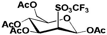 |
25 KHCO3/50 K2.2.2 | MeCN, 0.125 H2O | 42 | 41 ± 13, n = 3 | 22 ± 11, n = 3 | 81 ± 13, n = 3 |
| 4 | 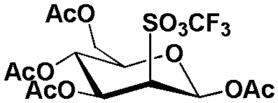 |
25 N-Ethyl4 HCO3 | MeCN, 0.5% H2O | 48 | 93 ± 4, n = 3 | 78 ± 7, n = 3 | 84 ± 7, n = 3 |
| 5 |  |
25 K2CO3/100 K2.2.2 | MeCN, 0.5% H2O | 48 | 79 ± 8, n = 4 | 41 ± 21, n = 4 | 39 ± 9, n = 4 |
| 6 |  |
50 KHCO3/100 K2.2.2 | MeCN, 0.5% H2O | 47 | 96 ± 5, n = 3 | 64 ± 17, n = 3 | 89 ± 5, n = 3 |
| 7 |  |
12 K2CO3/48 K2.2.2 | 9:1 MeCN:Thexyl alcohol 0.5% H2O |
21 | 18 | 8 | 94 |
| 8 |  |
25 N-Ethyl4 HCO3 | 1:3 MeCN:Thexyl alcohol 0.5% H2O |
54 | 93 ± 4, n = 3 | 44 ± 5, n = 3 | 50 ± 4, n = 3 |
| 9 | 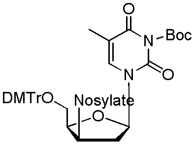 |
25 KHCO3/50 K2.2.2 | 1:3 MeCN:Thexyl alcohol 0.5% H2O |
51 | 77 ± 3, n = 3 | 60 ± 3, n = 3 | 96 ± 2, n = 3 |
| 10 |  |
25 K2CO3/100 K2.2.2 | MeCN, 0.5% H2O | 39 | 73 ± 4, n = 3 | 65 ± 7, n = 3 | 91 ± 10, n = 3 |
The radiofluorination efficiency of mannose triflate was optimized with approximately 1:1.9 ratios of base and precursor. Radiofluorination of mannose triflate is typically carried out with K2CO3 and K2.2.234 but in our study, the radiofluorination of mannose triflate with this PTC resulted in low radiofluorination efficiency, although the recovery of the radioactivity from PS-Im+Cl− monolith was high. To improve the radiofluorination efficiency of mannose triflate, we attempted to use thexyl alcohol as a co-solvent as reported by Kim et al.;35 however, the radiofluorination efficiency was not improved. We found that switching the PTC to 25 mM NEthyl+HCO3− solution in MeCN with 0.5% water (Table 2, entry 4) at a flow rate of 10 μL min−1 (residence time of 78 seconds) resulted in 78 ± 7% (n = 3) decay-corrected radiochemical yield. We also obtained similar radiochemical yield of 86 ± 7%, n = 4 (Table 3, entry 2) with shorter residence time of 7.8 seconds (flow rate 100 μL min−1).
| Entry | Precursor | Base | Solvent | Conc. precursor (mM) | % Fluorination eff. | % R.C.Ya | % Releasing eff. |
|---|---|---|---|---|---|---|---|
| a R.C.Y is calculated by multiplying the radiofluorination efficiency (based on radio-TLC) and the percent ratio of (collected radioactivity after fluorination/starting radioactivity trapped on the PS-Im+Cl− monolith). | |||||||
| 1 |  |
25 K2CO3/100 K2.2.2 | MeCN, 0.5% H2O | 39 | 34 ± 10, n = 2 | 30 ± 15, n = 2 | 92 ± 11, n = 2 |
| 2 |  |
25 N-Ethyl4 HCO3 | MeCN, 0.5% H2O | 48 | 92 ± 2, n = 4 | 86 ± 7, n = 4 | 90 ± 2 n = 3 |
| 3 |  |
25 KHCO3/50 K2.2.2 | 1:3 MeCN:Thexyl alcohol 0.5% H2O |
49 | 41 ± 8, n = 3 | 24 ± 10, n = 3 | 59 ± 15, n = 3 |
| 4 |  |
50 KHCO3/100 K2.2.2 | MeCN, 0.5% H2O | 50 | 25 ± 7, n = 2 | 15 ± 2, n = 2 | 67 ± 28, n = 2 |
Conventionally, radiofluorination of FB-precursor is carried out in DMSO,36 but due to the high viscosity of DMSO (1.996 mPa s) and the small dimension of the ETFE tubing and the microfluidic chip, the radiofluorination of FB-precursor was carried out in MeCN (viscosity 0.343 mPa s). The radiofluorination of FB-precursor was initially carried out with 1:2 ratio of K2CO3 to FB-precursor with a flow rate of 10 μL min−1, resulting in an overall radiochemical yield of 41 ± 21% (n = 4). The radiofluorination efficiency was high (79 ± 8%, n = 4), but the recovery of the radioactivity from the PS-Im+F− monolith was poor (Table 2, Entry 5). Furthermore, we observed the formation of a precipitate upon dissolving the FB-precursor with the K2CO3/K2.2.2 solution, which might have resulted in the lower releasing efficiency of the [18F]fluoride ions from the PS-Im+F− monolith. To improve the overall radiochemical yield, we investigated KHCO3 as the base for the radiofluorination of the FB precursor. The use of KHCO3/K2.2.2 and FB precursor mixture did not form any precipitate. The radiochemical yield of 4-[18F]fluoro-ethyl benzoate was improved from 41% to 64% (Table 2, entry 5 versus entry 6) switching to a PTC consisting of a 2:1 ratio of KHCO3 to FB-precursor. The optimal flow rate and residence time were found to be 10 μL min−1 and 78 second. At higher flow rate, of 100 μL min−1 (7.8 s residence time), the radiochemical yield dropped from 64 ± 17% (n = 3) to 15 ± 2% (n = 2) (Table 2, entry 6).
The radiofluorination of FLT-precursor, 3-N-tert-butoxycarbonyl-(5′-O-(4,4′-dimethoxytriphenylmethyl)-2′-deoxy-3′-O-(4-nitrobenzenesulfonyl)-β-D-threopentofuranosyl)thymine, was carried out with approximately 1:2 ratio base to precursor concentration in acetonitrile. The use of KHCO3 gave the highest radiofluorination efficiency of 93% ± 4 (n = 3) in a 3:1 ratio of thexyl alcohol/acetonitrile solution at a flow rate of 10 μL min−1 (Table 2, entry 8). However we found that the [18F]fluoride recovery from the PS-Im+F− monolith was poor when the cation of the PTC was changed from K+/K2.2.2 to NEthyl4+ (Table 2, Entry 8 and 9). Furthermore, the NEthyl4+HCO3− PTC resulted in the formation of a red precipitate during the fluorination reaction, which clogged the microfluidic channel. Similarly to the radiofluorination of the FB-precursor, the radiofluorination of FLT-precursor was lower at a flow rate of 100 μL min−1 with residence time of 7.8 seconds than at 10 μL min−1 (Table 3, entry 3).
The optimized radiofluorination condition of tosyl-fallypride was carried out with approximately 1:1.6 ratio of K2CO3 to precursor concentration in MeCN and 0.5% water to achieve a radiochemical yield of 73 ± 4% (n = 3) (Table 2, Entry 10). No radiofluorination product was observed when KHCO3/K2.2.2 or NEthyl4+HCO3− were used as the PTC. The use of thexyl alcohol also resulted in no radiofluorination product. Similarly to our observation with FLT and FB precursors, the radiochemical yield of [18F]fallypride at a lower flow rate of 10 μL min−1 (resident time of 78 second) was higher than at a faster flow rate of 100 μL min−1 (resident time 7.8 seconds).
Specific activity studies were conducted using FLT-precusor using the set-up shown in Fig. 1b. First [18F]fluoride from cyclotron was flowed through the PS-Im+ monolith inside ETFE tubing without addition of KF. This was followed by a solution of FLT precursor and KHCO3 (2:1 molar ratio) in acetonitrile, which was directly flowed into the preheated glass microfluidic chip. The products was collected in a eppendroff tube and hydrolysed with 200uL of 1 M HCl at 100 °C. The specific activity of [18F]FLT using this set-up was determined to be 21 GBq/umol (n.d.c). It is known that the specific activity of a radioisotope depends on the initial activity used in the experiment and decreases exponentially with time as shown in equation below,
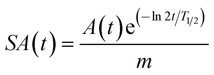
A is the amount of radioactivity (Bq), t is time (s) T1/2 is half life of a radioisotope(s) for 18F and m is mass in mols.37 In our experiment, we use low activity in the range of 74 MBq to measure the specific activity, hence a lower specific activity was obtained. Upon increasing the initially activity, the specific activity can be increased using this system.
We have demonstrated comparable radiochemical yield of the fluorinated intermediate to conventional methods using [18F]fluoride ions that were concentrated and activated on the imidazolium monolith in a simple flow-through system without performing an additional azeotropic distillation step. The leaving group reactivity of the precursors dictated the extent of radiofluorination of the precursors as observed at a higher flow rate of 100 μL min−1 (residence time 7.8 second) (Table 3). Our observation is consistent with literature, in which mannose triflate is the most reactive precursors and the FB-precursor is the least reactive precursor that were investigated in this study. Although the nosylate group is known to be more reactive than the tosyl group, our result with the FLT and fallypride precursor yielded comparable yield (within experimental error). This observation may be attributable to a steric factor, in which the FLT precursor is a secondary substrate while the tosyl-fallypride is a primary substrate.
Materials
All chemicals and solvents were purchased from Sigma-Aldrich (Milwaukee, WI, USA). Ethylene dimethacrylate (EDMA), divinylbenzene (DVB) and 4-vinylbenzyl chloride (VBC) were filtered with basic alumina oxide to remove the stabilizer. Tosyl-fallypride, mannose triflate, 3-N-Boc-5′-O-dimethoxytrityl-3′-O-nosyl-thymidine, 4-(ethoxycarbonyl)-N,N,N-trimethylbenzenaminium triflate were purchased from ABX (Advanced Biochemical Compounds; Radeberg, Germany) and used without further purification. Ethylenetetrafluoroethylene (ETFE) (OD: 0.159 cm) tubing with 400 μm inner diameter was purchased from McMaster-Carr (Santa Fe Springs, CA, USA). A 470 nm LED array (RLT-MIL470-12B-30) was purchased from Roithner LASER Technik (Vienna, Austria) consisted of 12 LEDs emitting at 470 nm with 20 mW of power each. Microprocessor-Controlled UV-crosslinker Spectrolinker TM XL-1000 was bought from Spectronics Corporation (Westbury, NY, USA). Microfluidic chip (150 μm × 150 μm × 5000 μm), FC_R150.676.2_PACK with chip holder was purchased from Micronit Microfluidics (The Netherlands). Analytical HPLC was performed on a Knauer Smartline HPLC system (1 mL min−1) with a Phenomenex reverse-phase Luna column (5 μm, 4.6 mm × 250 mm) (California, U.S.A) with inline Knauer UV detector (254 nm) and a gamma-radiation coincidence detector and counter (B-FC-4100 and B-FC-1000) (Bioscan, Washington D.C., U.S.A). Radio-TLC plates were scanned with miniGitastar (Raytest, Wilmington, NC, USA).No-carrier-added [18F]fluoride was produced by the (p,n) reaction of recycled [18O]H2O (85% isotopic purity, IBA) in a RDS-112 cyclotron (Siemens; Knoxville, TN, USA) at 11 MeV using a 300 μL or 1 mL tantalum target with havar foil.
Experimental
:1 ratio of THF and water with potassium fluoride (0.3 mM). 200 μL of this solution (corresponds to the amount of fluoride ions present in 74 GBq of activity) was flowed through the imidazolium monolith in microfluidic chip using a syringe pump at flow rate of 250 μL min−1.
Conclusions
We have developed a new method for concentrating and activating [18F]fluoride ions in microliter volumes on a flow-through microfluidic chip and ETFE tubing that were functionalized with PS-Im+Cl− monolith. The [18F]fluoride ions were directly used to fluorinate various PET probe precursors with diverse reactivity in a continuous flow microfluidic chip. This new flow-through platform enables the concentration and activation of [18F]F− ions with high radioactivity recovery, which can be easily integrated with any flow through microfluidic devices and yet maintained a small overall footprint of the microfluidic radiosynthesizer. Based on this new method, the entire radiofluorination process, starting with 1 mL of [18F]F−/[18O]H2O from the cyclotron target to produce the fluorinated product on a flow-through platform takes about 24 minutes. For the radiofluorination of the more reactive mannose triflate (precursor for the synthesis of [18F]FDG), the entire process can be shortened to about 6 minutes. We anticipate this method has the potential to expand the usefulness of flow-through microfluidics for radiosynthesis by providing a means to perform the critical solvent-exchange step entirely within microfluidics rather than requiring macroscale components for synthesizing a diverse arrays of PET probes on-demand.References
- J. R. Goodell, J. P. McMullen, N. Zaborenko, J. R. Maloney, C.-X. Ho, K. F. Jensen, J. A. Porco and A. B. Beeler, J. Org. Chem., 2009, 74, 6169–6180 CrossRef CAS PubMed.
- A. M. Elizarov, Lab Chip, 2009, 9, 1326 RSC.
- G. Pascali, P. Watts and P. A. Salvadori, Nucl. Med. Biol., 2013, 6, 776–787 CrossRef PubMed.
- P. Y. Keng, M. Ester and R. M. van Dam, in Positron Emission Tomography-Current Clinical and Research Aspect, InTech, 2012 Search PubMed.
- M. E. Phelps, Proc. Natl. Acad. Sci. U. S. A., 2000, 97, 9226–9233 CrossRef CAS.
- P. Y. Keng, S. Chen, H. Ding, S. Sadeghi, G. J. Shah, A. Dooraghi, M. E. Phelps, N. Satyamurthy, A. F. Chatziioannou, C.-J. Kim and R. M. van Dam, Proc. Natl. Acad. Sci. U. S. A., 2011, 17, 690–695 Search PubMed.
- C.-C. Lee, G. Sui, A. Elizarov, C. J. Shu, Y.-S. Shin, A. N. Dooley, J. Huang, A. Daridon, P. Wyatt, D. Stout, H. C. Kolb, O. N. Witte, N. Satyamurthy, J. R. Heath, M. E. Phelps, S. R. Quake and H.-R. Tseng, Science, 2005, 310, 1793–1796 CrossRef CAS PubMed.
- V. Arima, G. Pascali, O. Lade, H. R. Kretschmer, I. Bernsdorf, V. Hammond, P. Watts, F. D. Leonardis, M. D. Tarn, N. Pamme, B. Z. Cvetkovic, P. S. Dittrich, N. Vasovic, R. Duane, A. Jaksic, A. Zacheo, A. Zizzari, L. Marra, E. Perrone, P. A. Salvadori and R. Rinaldi, Lab Chip, 2013, 13, 2328–2336 RSC.
- A. Lebedev, R. Miraghaie, K. Kotta, C. E. Ball, J. Zhang, M. S. Buchsbaum, H. C. Kolb and A. Elizarov, Lab Chip, 2012, 13, 136–145 RSC.
- A. M. Elizarov, R. M. van Dam, Y. S. Shin, H. C. Kolb, H. C. Padgett, D. Stout, J. Shu, J. Huang, A. Daridon and J. R. Heath, J. Nucl. Med. Off. Publ. Soc. Nucl. Med., 2010, 51, 282–287 CAS.
- J. M. Gillies, C. Prenant, G. N. Chimon, G. J. Smethurst, B. A. Dekker and J. Zweit, Appl. Radiat. Isot., 2006, 64, 333–336 CrossRef CAS PubMed.
- C. J. Steel, A. T. O'Brien, S. K. Luthra and F. Brady, J. Label. Compd. Radiopharm., 2007, 50, 308–311 CrossRef CAS.
- W. H. Grover, R. H. C. Ivester, E. C. Jensen and R. A. Mathies, Lab Chip, 2006, 6, 623–631 RSC.
- H. Usutani, Y. Tomida, A. Nagaki, H. Okamoto, T. Nokami and J. Yoshida, J. Am. Chem. Soc., 2007, 129, 3046–3047 CrossRef CAS PubMed.
- I. R. Baxendale, J. Deeley, C. M. Griffiths-Jones, S. V. Ley, S. Saaby and G. K. Tranmer, Chem. Commun., 2006, 2566–2568 RSC.
- A. Hibara, K. Toshin, T. Tsukahara, K. Mawatari and T. Kitamori, Chem. Lett., 2008, 37, 1064–1065 CrossRef CAS.
- B. Z. Cvetković, O. Lade, L. Marra, V. Arima, R. Rinaldi and P. S. Dittrich, RSC Adv., 2012, 2, 11117–11122 RSC.
- F. De Leonardis, G. Pascali, P. A. Salvadori, P. Watts and N. Pamme, J. Chromatogr. A, 2011, 1218, 4714–4719 CrossRef CAS PubMed.
- J.-H. Chun, S. Lu, Y.-S. Lee and V. W. Pike, J. Org. Chem., 2010, 75, 3332–3338 CrossRef CAS PubMed.
- K. Hamacher, T. Hirschfelder and H. Coenen, Appl. Radiat. Isot., 2002, 56, 519–523 CrossRef CAS.
- H. Saiki, R. Iwata, H. Nakanishi, R. Wong, Y. Ishikawa, S. Furumoto, R. Yamahara, K. Sakamoto and E. Ozeki, Appl. Radiat. Isot., 2010, 68, 1703–1708 CrossRef CAS PubMed.
- S. Sadeghi, V. Liang, S. Cheung, S. Woo, C. Wu, J. Ly, Y. Deng, M. Eddings and R. M. van Dam, Appl. Radiat. Isot., 2013, 75, 85–94 CrossRef CAS PubMed.
- R. Wong, R. Iwata, H. Saiki, S. Furumoto, Y. Ishikawa and E. Ozeki, Appl. Radiat. Isot., 2012, 70, 193–199 CrossRef CAS PubMed.
- J. Aerts, S. Voccia, C. Lemaire, F. Giacomelli, D. Goblet, D. Thonon, A. Plenevaux, G. Warnock and A. Luxen, Tetrahedron Lett., 2010, 51, 64–66 CrossRef CAS PubMed.
- S. H. Wessmann, G. Henriksen and H. Wester, Nuklearmedizin, 2012, 51, 1–8 CAS.
- S. Frantisek, J. Chromatogr. A, 2010, 1217, 902–924 CrossRef PubMed.
- C. W. Huck and G. K. Bonn, Chem. Eng. Technol., 2005, 28, 1457–1472 CrossRef CAS.
- K. Sato, S. Arai and T. Yamagishi, Tetrahedron Lett., 1999, 40, 5219–5222 CrossRef CAS.
- E. Alcalde, I. Dinarès, A. Ibáñez and N. Mesquida, Chem. Commun., 2011, 47, 3266–3268 RSC.
- I. Dinarès, C. G. de Miguel, A. Ibáñez, N. Mesquida and E. Alcalde, Green Chem., 2009, 11, 1507–1510 RSC.
- J. Yoon, S. K. Kim, N. J. Singh and K. S. Kim, Chem. Soc. Rev., 2006, 35, 355–360 RSC.
- Z. Walsh, P. A. Levkin, B. Paull, F. Svec and M. Macka, J. Sep. Sci., 2011, 33, 61–66 CrossRef PubMed.
- D. Connolly and B. Paull, J. Sep. Sci., 2009, 32, 2653–2658 CrossRef CAS PubMed.
- C. Lemaire, P. Damhaut, B. Lauricella, C. Mosdzianowski, J.-L. Morelle, M. Monclus, J. Van Naemen, E. Mulleneers, J. Aerts, A. Plenevaux, C. Brihaye and A. Luxen, J. Label. Compd. Radiopharm., 2002, 45, 435–447 CrossRef CAS.
- Y.-H. Oh, D.-S. Ahn, S.-Y. Chung, J.-H. Jeon, S.-W. Park, S. J. Oh, D. W. Kim, H. S. Kil, D. Y. Chi and S. Lee, J. Phys. Chem., 2007, 111, 10152–10161 CrossRef CAS PubMed.
- J. Becaud, L. Mu, M. Karramkam, P. A. Schubiger, S. M. Ametamey, K. Graham, T. Stellfeld, L. Lehmann, S. Borkowski, D. Berndorff, L. Dinkelborg, A. Srinivasan, R. Smits and B. Koksch, Bioconjugate Chem., 2009, 20, 2254–2261 CrossRef CAS PubMed.
- J. Bergman, O. Eskola, P. Lehikoinen and O. Solin, Appl. Radiat. Isot., 2001, 54, 927–933 CrossRef CAS.
Footnote |
| † Electronic supplementary information (ESI) available. See DOI: 10.1039/c4ra04064c |
| This journal is © The Royal Society of Chemistry 2014 |