DOI:
10.1039/C4RA03700F
(Paper)
RSC Adv., 2014,
4, 34801-34815
Factors controlling the photoresponse of copper(I) diimine dyes containing hole-transporting dendrons in dye-sensitized solar cells: substituent and solvent effects†
Received
23rd April 2014
, Accepted 23rd July 2014
First published on 13th August 2014
Abstract
Two series of 2,2′-bipyridine (bpy) ligands bearing different 6,6′-substituents (Me, nBu, isoBu, hexyl, Ph and 2-naphthyl) and carrying first-generation (ligands 1–6) or second-generation (ligands 7–12) hole transporting dendrons in the 4,4′-positions are reported. They have been incorporated into homoleptic copper(I) complexes [CuL2][PF6]. FTO/TiO2 electrodes functionalized with the anchoring ligand ((6,6′-dimethyl-[2,2′-bipyridine]-4,4′-diyl)bis(4,1-phenylene))bis(phosphonic acid), 13, were dipped in either CH2Cl2 or acetone solutions of [CuL2][PF6] to produce two series of surface-bound heteroleptic dyes. Their performances in dye-sensitized solar cells (DSCs) are assessed. Solid-state absorption spectra of dye-functionalized electrodes show that dye uptake is greater if acetone is used in the dye-dipping cycle rather than CH2Cl2, and the DSCs made using acetone generally perform better than analogous DSCs made using CH2Cl2. Using acetone-dipping solutions, the best DSC efficiencies are obtained with the second-generation dyes [Cu(13)(L)]+ (L = 7–11 with Me, nBu, isoBu, hexyl, Ph groups); [Cu(13)(12)]+ (12 contains 2-naphthyl groups in the 6,6′-positions) and its first-generation analogue [Cu(13)(6)]+ perform poorly. When CH2Cl2 is used in the dipping cycle, DSCs with dyes [Cu(13)(1)]+ and [Cu(13)(7)]+ (6,6′-Me2-substituted) show the highest VOC, JSC and η values, and EQE spectra confirm electron injection over a wider energy range than for other dyes. For CH2Cl2 in the dipping cycle (but not for acetone), [Cu(13)(5)]+ (6,6′-Ph2-substituted) performs as well as [Cu(13)(1)]+. The overall results of the study indicate that a combination of small 6,6′-substituents and acetone in the dye-dipping cycle lead to the best performing dyes.
Introduction
Conventional Grätzel dye-sensitized solar cells (DSCs) incorporate ruthenium(II) complexes as photosensitizers.1 Our ongoing focus on DSCs containing copper(I) complexes as sensitizers is predicated both upon their possessing similar photophysical properties to ruthenium(II) complexes,2,3 and upon the greater abundance of copper than ruthenium in the Earth. Sauvage and co-workers pioneered the introduction of copper(I) complexes in DSCs,4 and more recent uses of copper(I) in dyes in DSCs have been surveyed by Robertson5 and by us.6 The recent report of a remarkable photoconversion efficiency of 4.66% for a DSC with a heteroleptic copper(I) dye containing 6,6′-dimesityl-2,2′-bipyridine-4,4′-dicarboxylic acid as the anchoring ligand and a 2,2′-bipyridine ancillary ligand with triphenylamino domains underlines the potential of copper(I) sensitizers.7 In the latter case, the efficiency was enhanced by using the co-adsorbant chenodeoxycholic acid.
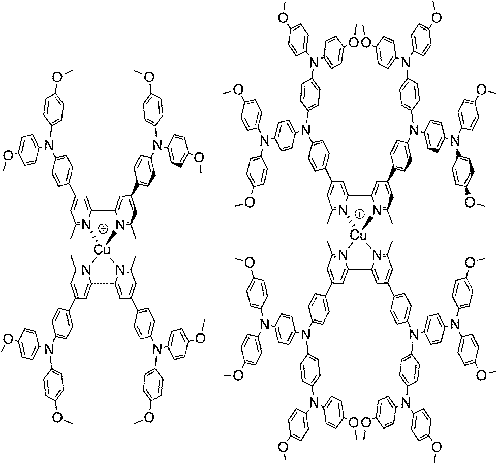
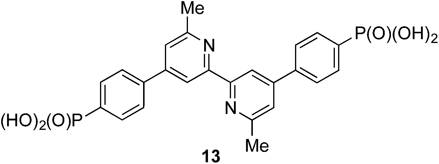
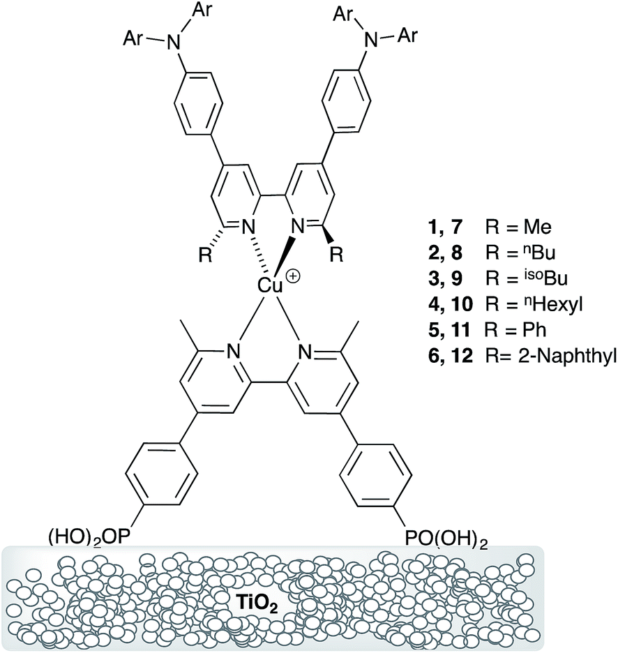
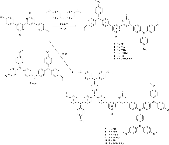
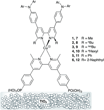
We recently described the syntheses and characterization of the two copper(I) diimine complexes incorporating ligands containing first- and second-generation hole-transport dendrons (Scheme 1). For both ligands, semi-empirical MO calculations at the PM3 level showed that the HOMOs (degenerate set) and LUMO are localized on the dendron and 2,2′-bipyridine (bpy) metal-binding unit, respectively.8 By applying a ligand exchange strategy,9 we assembled dye-sensitized solar cells (DSCs) containing dyes [Cu(Lancillary)(Lanchor)]+ anchored on mesoporous TiO2. The combination of the hole-transport substituents in the ancillary ligands with the anchoring ligand 6,6′-dimethyl-2,2′-bipyridine-4,4′-bis(phosphonic acid) resulted in power-to-current conversion efficiencies of 20.7% relative to 100% for N719 measured under the same conditions in fully masked DSCs.8 We have also established that the photoresponse of a [Cu(Lancillary)(Lanchor)]+ dye can be significantly improved by introducing an aromatic linker between the bpy and phosphonate domains of the anchoring ligand, and by replacing the 6- and 6′-methyl substituents in the ancillary ligand by isobutyl or phenyl groups.10 We now describe a systematic extension of these studies in which the ancillary bpy ligands (1–12 in Scheme 2) contain (i) first- or second-generation hole-transport dendrons and (ii) alkyl or aromatic substituents of varying steric bulk in the 6,6′-positions. The anchoring ligand in the [Cu(Lancillary)(Lanchor)]+ dyes is 13 (Scheme 3) which has shown the greatest potential in recent studies. The heteroleptic complex is assembled using ligand exchange between surface-anchored ligand Lanchor and a homoleptic complex [Cu(Lancillary)2]+. This approach circumvents the need to isolate the heteroleptic species (which is often not possible because of the rapid establishment of statistical solution equilibria between homo- and heteroleptic species). Characterisation of related surface species has previously been carried out.9
 |
| | Scheme 1 Homoleptic copper(I) diimine complexes with ligands containing first- and second-generation hole-transport dendrons.8 | |
 |
| | Scheme 2 Synthetic route to compounds 1–12. Conditions: (i) NaOtBu; (ii) Pd(bda)2, PtBu3, toluene, 100 °C, 16 h. Pd(bda)2 = bis(dibenzylideneacetone)palladium(0). | |
 |
| | Scheme 3 Structure of anchoring ligand 13. | |
Experimental
General
A Bruker Avance III-500 NMR spectrometer was used to record 1H and 13C NMR spectra, and chemical shifts were referenced to residual solvent peaks with respect to ∂(TMS) = 0 ppm. Solution absorption spectra were recorded with a Cary 5000 spectrophotometer and FT-IR spectra of solid samples on a Perkin Elmer UATR Two spectrometer. MALDI-TOF and electrospray ionization (ESI) mass spectra were recorded on Bruker Daltonics microflex and Bruker esquire 3000plus instruments, respectively. Electrochemical measurements were made using a CH Instruments 900B potentiostat with glassy carbon, platinum wire and silver wire as the working, counter, and reference electrodes, respectively. Substrates were dissolved in HPLC grade CH2Cl2 (ca. 10−4 to 10−5 mol dm−3) containing 0.1 mol dm−3 [nBu4N][PF6] as the supporting electrolyte; all solutions were degassed with argon. Cp2Fe was used as internal reference.
The external quantum efficiency (EQE) measurements were made using a Spe-Quest quantum efficiency instrument from Rera Systems (Netherlands) equipped with a 100 W halogen lamp (QTH) and a lambda 300 grating monochromator (Lot Oriel). The monochromatic light was modulated to 3 Hz using a chopper wheel (ThorLabs). The cell response was amplified with a large dynamic range IV converter (CVI Melles Griot) and then measured with a SR830 DSP Lock-In amplifier (Stanford Research).
Compounds 1 and 7,8 anchoring ligand 13,10 [Cu(MeCN)4][PF6],11 [Cu(1)2][PF6]8 and [Cu(7)2][PF6]8 were prepared as previously reported. The syntheses and characterization data of the ligands and the numbering scheme for the NMR assignments are given in the ESI.†
[Cu(2)2][PF6]
[Cu(MeCN)4][PF6] (35.2 mg, 0.094 mmol) was reacted with 2 (165 mg, 0.189 mmol) in a mixture of MeCN (15 mL) and CH2Cl2 (15 mL). The solution turned red immediately and was stirred overnight at room temperature. Then, the volume of the solvent was reduced in vacuo and the product was precipitated by addition of Et2O. The solid was separated by filtration, was washed with Et2O and was dried in a stream of air. [Cu(2)2][PF6] was isolated as a red solid (145 mg, 0.074 mmol, 78%). 1H NMR (500 MHz, CDCl3) ∂/ppm: 8.27 (d, J = 1.2 Hz, 4H, HA3), 7.59 (d, J = 8.8 Hz, 8H, HB2), 7.57 (d, J = 1.2 Hz, 4H, HA5), 7.14 (d, J = 9.0 Hz, 16H, HC2), 7.02 (d, J = 8.8 Hz, 8H, HB3), 6.89 (d, J = 9.0 Hz, 16H, HC3), 3.83 (s, 24H, OMe), 2.62 (t, J = 8.2 Hz, 8H, Ha), 1.44–1.32 (m, 8H, Hb), 0.90 (tq, J = 7.4 Hz, 8H, Hc), 0.48 (t, J = 7.4 Hz, 12H, Hd).13C NMR (126 MHz, CDCl3) ∂/ppm: 161.5 (CA6), 156.8 (CC4), 152.6 (CA2), 150.8 (CB4), 150.2 (CB1), 139.8 (CC1), 127.8 (CB2), 127.5 (CC2), 127.3 (CA4), 121.8 (CA5), 119.4 (CB3), 116.3 (CA3), 115.1 (CC3), 55.7 (OMe), 39.8 (Ca), 31.9 (Cb), 22.7 (Cc), 13.6 (Cd). IR (![[small nu, Greek, tilde]](https://www.rsc.org/images/entities/i_char_e0e1.gif) /cm−1): 3187 (w), 3036 (w), 2997 (w), 2952 (w), 2924 (w), 2866 (w), 2853 (w), 2832 (w), 1595 (s), 1501 (s), 1462 (m), 1440 (m), 1321 (m), 1237 (s), 1195 (m), 1179 (m), 1102 (m), 1031 (m), 838 (s), 824 (s), 728 (m), 574 (m), 557 (m), 527 (m). ESI MS (m/z): 1813.8 [M − PF6]+, (calc. 1813.8). UV-VIS (CH2Cl2, 1.0 × 10⁻⁵ mol dm−3): λmax/nm 306 (ε/dm3 mol−1 cm−1 67
/cm−1): 3187 (w), 3036 (w), 2997 (w), 2952 (w), 2924 (w), 2866 (w), 2853 (w), 2832 (w), 1595 (s), 1501 (s), 1462 (m), 1440 (m), 1321 (m), 1237 (s), 1195 (m), 1179 (m), 1102 (m), 1031 (m), 838 (s), 824 (s), 728 (m), 574 (m), 557 (m), 527 (m). ESI MS (m/z): 1813.8 [M − PF6]+, (calc. 1813.8). UV-VIS (CH2Cl2, 1.0 × 10⁻⁵ mol dm−3): λmax/nm 306 (ε/dm3 mol−1 cm−1 67![[thin space (1/6-em)]](https://www.rsc.org/images/entities/char_2009.gif) 500), 386 (60400), 480 sh (27500). Found: C, 71.69; H, 6.32; N, 5.52; C116H116N8O8CuPF6 requires C, 71.13; H, 5.97; N, 5.72 (%).
500), 386 (60400), 480 sh (27500). Found: C, 71.69; H, 6.32; N, 5.52; C116H116N8O8CuPF6 requires C, 71.13; H, 5.97; N, 5.72 (%).
[Cu(3)2][PF6]
The method was as for [Cu(2)2][PF6] starting with [Cu(MeCN)4][PF6] (47.9 mg, 0.128 mmol) and 3 (225 mg, 0.257 mmol) was isolated as red solid (105 mg, 0.054 mmol, 42%).1H NMR (500 MHz, CDCl3) ∂/ppm: 8.27 (s, 4H, HA3), 7.60 (d, J = 8.5 Hz, 8H, HB2), 7.52 (s, 4H, HA5), 7.14 (d, J = 8.7 Hz, 16H, HC2), 7.02 (d, J = 8.6 Hz, 8H, HB3), 6.89 (d, J = 8.4 Hz, 16H, HC3), 3.83 (s, 24H, HOMe), 2.47 (d, J = 7.4 Hz, 8H, Ha), 1.69 (m, 4H, Hb), 0.54 (d, J = 6.7 Hz, 24H, Hc).13C NMR (126 MHz, CDCl3) ∂/ppm: 160.5 (CA6), 156.9 (CC4), 153.1 (CA2), 149.9 (CB1, CB4), 139.9 (CC1), 127.9 (CB2), 127.6 (CA4, CC2), 122.8 (CA5), 119.5 (CB3), 116.5 (CA3), 115.1 (CC3), 55.7 (COMe), 48.8 (Ca), 28.5 (Cb), 22.2 (Cc). IR (/cm−1): 3190 (w), 3033 (w), 2997 (w), 2953 (w), 2929 (w), 2866 (w), 2834 (w), 1594 (s), 1504 (s), 1463 (m), 1440 (m), 1322 (m), 1289 (m), 1239 (s), 1196 (m), 1179 (m), 1102 (m), 1032 (m), 825 (s), 597 (m), 574 (m), 557 (m), 531 (m). ESI MS (m/z): 1814.8 [M − PF6]+ (calc. 1813.8), 875.6 [3 + H]+ (base peak, calc. 875.5). UV-VIS (CH2Cl2, 1.0 × 10⁻⁵ mol dm−3): λmax/nm 305 (ε/dm3 mol−1 cm−1 63000), 393 (58700), 480 sh (28200). Found: C, 70.14; H, 6.30; N, 5.48; C116H116N8O8CuPF6·H2O requires C, 70.48; H, 6.02; N, 5.67 (%).
[Cu(4)2][PF6]
The method was as for [Cu(2)2][PF6] starting with [Cu(MeCN)4][PF6] (31.7 mg, 0.085 mmol) and 4 (158 mg, 0.17 mmol). [Cu(4)2][PF6] was isolated as a red solid (153 mg, 0.074 mmol, 86%). 1H NMR (500 MHz, CDCl3) ∂/ppm: 8.26 (d, J = 1.4 Hz, 4H, HA3), 7.58 (d, J = 8.9 Hz, 8H, HB2), 7.56 (d, J = 1.4 Hz, 4H, HA5), 7.13 (d, J = 9.0 Hz, 16H, HC2), 7.02 (d, J = 8.9 Hz, 8H, HB3), 6.89 (d, J = 9.0 Hz, 16H, HC3), 3.83 (s, 24H, HOMe), 2.61 (t, J = 8.2 Hz, 8H, Ha), 1.38 (m, 8H, Hb), 0.95 (m, 8H, Hd), 0.86 (m, 8H, Hc), 0.77 (m, 8H, He), 0.62 (t, J = 7.3 Hz, 12H, Hf). 13C NMR (126 MHz, CDCl3) ∂/ppm: 161.6 (CA6), 156.8 (CC4), 152.6 (CA2), 150.8 (CB4), 150.2 (CB1), 139.8 (CC1), 127.8 (CB2), 127.5 (CC2), 127.2 (CA4), 121.8 (CA5), 119.4 (CB3), 116.2 (CA3), 115.1 (CC3), 55.7 (COMe), 40.1 (Ca), 31.5 (Ce), 30.0 (Cb), 29.5 (Cc), 22.6 (Cd), 14.1 (Cf). IR (/cm−1): 3187 (w), 3036 (w), 2997 (w), 2947 (w), 2924 (w), 2853 (w), 2835 (w), 1594 (s), 1504 (s), 1461 (m), 1327 (m), 1294 (m), 1239 (s), 1200 (m), 1179 (m), 1102 (m), 1031 (m), 838 (s), 825 (s), 729 (m), 663 (m), 573 (m), 557 (m), 535 (m). ESI MS (m/z): 1926.0 [M − PF6]+ (base peak, calc. 1924.5), 932.2 [4 + H]+ (calc. 931.5). UV-VIS (CH2Cl2, 1.0 × 10⁻⁵ mol dm−3): λmax/nm 306 (ε/dm3 mol−1 cm−1 65700), 388 (60000), 480 sh (28000). Found: C, 68.93; H, 6.12; N, 5.46; C124H132N8O8CuPF6·4H2O requires C, 69.50; H, 6.58; N, 5.23 (%).
[Cu(5)2][PF6]
The method was as for [Cu(2)2][PF6] starting with [Cu(MeCN)4][PF6] (45.9 mg, 0.123 mmol) and 5 (225 mg, 0.246 mmol) in CH2Cl2 (40 mL), and the reaction mixture turned green-black. [Cu(5)2][PF6] was isolated as a green-black solid (225 mg, 0.11 mmol, 90%). 1H NMR (500 MHz, CDCl3) ∂/ppm: 7.95 (d, J = 1.2 Hz, 4H, HA3), 7.61 (d, J = 1.2 Hz, 4H, HA5), 7.58 (m, 8H, HD2), 7.56 (d, J = 8.8 Hz, 8H, HB2), 7.17 (d, J = 9.0 Hz, 16H, HC2), 7.05 (d, J = 8.8 Hz, 8H, HB3), 7.03 (m, 4H, HD4), 6.92 (d, J = 9.0 Hz, 16H, HC3), 7.03 (m, 8H, HD3), 3.84 (s, 24H, HOMe). 13C NMR (126 MHz, CDCl3) ∂/ppm: 157.0 (CA6), 156.9 (CC4), 153.6 (CA2), 150.9 (CB4), 149.9 (CB1), 139.8 (CC1), 138.7 (CD1), 129.2 (CD4), 127.8 (CB2), 127.7 (CD2, CD3), 127.6 (CC2), 127.2 (CA4), 121.5 (CA5), 119.4 (CB3), 117.8 (CA3), 115.1 (CC3), 55.7 (COMe). IR (/cm−1): 3036 (w), 2999 (w), 2950 (w), 2931 (w), 2903 (w), 2832 (w), 1593 (s), 1504 (s), 1321 (m), 1238 (s), 1196 (m), 1179 (m), 1104 (m), 1030 (m), 824 (s), 773 (m), 741 (m), 729 (m), 696 (m), 576 (m), 557 (m), 527 (m). ESI MS (m/z): 1894.4 [M − PF6]+ (calc. 1893.7), 915.9 [5 + H]+ (base peak, calc. 915.4). UV-VIS (CH2Cl2, 1.0 × 10⁻⁵ mol dm−3): λmax/nm 286 (ε/dm3 mol−1 cm−1 79300), 331 (51600), 401 (55600), 560 sh (7000). Found: C, 73.04; H, 5.39; N, 5.30; C124H100N8O8CuPF6 requires C, 73.05; H, 4.94; N, 5.50 (%).
[Cu(6)2][PF6]
The method was as for [Cu(2)2][PF6] starting with [Cu(MeCN)4][PF6] (27.6 mg, 0.074 mmol) and 6 (150 mg, 0.148 mmol) in CH2Cl2 (40 mL). The reaction mixture was green-black, and [Cu(6)2][PF6] was isolated as a green-black solid (153 mg, 0.068 mmol, 92%). 1H NMR (500 MHz, CDCl3) ∂/ppm: 8.22 (s, 4H, HD1), 7.62 (m, 4H, HD3), 7.57 (m, 8H, HA5+D5/D8), 7.43 (d, J = 8.6 Hz, 4H, HD4), 7.32 (m, 16H, HA3+B2+D6/D7), 7.20 (d, J = 8.9 Hz, 16H, HC2), 7.14 (m, 8H, HD5/D8+D6/D7), 7.03 (d, J = 8.7 Hz, 8H, HB3), 6.95 (d, J = 9.0 Hz, 16H, HC3), 3.86 (s, 24H, HOMe). 13C NMR (126 MHz, CDCl3) ∂/ppm: 156.9 (CC4), 156.5 (CA6), 153.5 (CA2), 150.8 (CB4), 149.8 (CB1), 139.9 (CC1), 136.0 (CD2), 133.3 (CD4a/D8a), 132.2 (CD4a/D8a), 128.1 (CD5/D6/D7/D8), 127.9 (CB2), 127.6 (CC2), 127.5 (CD1+D4+D5/D8), 127.2 (CA4), 127.1 (CD6/D7), 126.4 (CD5/D6/D7/D8), 125.1 (CD3), 121.2 (CA5), 119.2 (CB3), 117.4 (CA3), 115.2 (CC3), 55.7 (COMe). IR (/cm−1): 3038 (w), 2999 (w), 2950 (w), 2929 (w), 2905 (w), 2832 (w), 1592 (s), 1504 (s), 1320 (m), 1239 (m), 1196 (m), 1179 (m), 1102 (m), 1032 (m), 824 (s), 781 (m), 755 (m), 741 (m), 576 (m), 557 (m), 533 (m), 477 (m). ESI MS (m/z): 2094.8 [M − PF6]+ (base peak, calc. 2093.8.), 1016.1 [6 + H]+ (calc. 1015.4). UV-VIS (CH2Cl2, 1.0 × 10⁻⁵ mol dm−3): λmax/nm 290 (ε/dm3 mol−1 cm−1 103100), 340 sh (55400), 408 (58000), 576 (5900). Found: C, 73.11; H, 5.18; N, 4.98; C140H108N8O8CuPF6·3H2O requires C, 73.33; H, 5.01; N, 4.89 (%).
[Cu(8)2][PF6]
The method was as for [Cu(2)2][PF6] starting with [Cu(MeCN)4][PF6] (27.6 mg, 73.9 μmol) and 8 (246 mg, 0.148 mmol) in MeCN (18 mL) and CH2Cl2 (18 mL). [Cu(8)2][PF6] was isolated as a red solid (202 mg, 57.2 μmol, 77%). 1H NMR (500 MHz, CD2Cl2) ∂/ppm: 8.34 (d, J = 1.0 Hz, 4H, HA3), 7.65 (d, J = 8.8 Hz, 8H, HB2), 7.60 (d, J = 1.0 Hz, 4H, HA5), 7.11 (d, J = 8.8 Hz, 8H, HB3), 7.07 (d, J = 9.0 Hz, 32H, HD2), 7.02 (d, J = 8.9 Hz, 16H, HC2), 6.90 (d, J = 8.9 Hz, 16H, HC3), 6.84 (d, J = 9.0 Hz, 32H, HD3), 3.77 (s, 48H, HOMe), 2.64 (t, J = 8.1 Hz, 8H, Ha), 1.39 (m, 8H, Hb), 0.90 (m, 8H, Hc),0.48 (t, J = 7.3 Hz, 12H, Hd). 13C NMR (126 MHz, CD2Cl2) ∂/ppm: 162.0 (CA6), 156.5 (CD4), 153.1 (CA2), 151.0 (CB4), 150.5 (CA4), 146.2 (CC4), 141.4 (CD1), 139.9 (CC1), 128.2 (CB2), 128.0 (CB1), 127.2 (CC2), 126.9 (CD2), 122.1 (CA5+C3), 120.1 (CB3), 116.8 (CA3), 115.2 (CD3), 56.0 (COMe), 40.2 (Ca), 32.4 (Cb), 23.1 (Cc), 13.8 (Cd). IR (/cm−1): 3036 (w), 2997 (w), 2954 (w), 2929 (w), 2905 (w), 2834 (w), 1595 (m), 1497 (s), 1313 (m), 1237 (s), 1033 (m), 824 (s), 576 (m), 539 (m). MALDI-TOF MS (m/z): 1728.2 [Cu(8)]+ (calc. 1726.7), 1664.8 [8 + H]+ (calc. 1664.8). UV-VIS (CH2Cl2, 1.0 × 10⁻⁵ mol dm−3): λmax/nm 225 (ε/dm3 mol−1 cm−1 170200), 309 (159600), 340 sh (134200), 480 sh (39600). Found: C, 73.53; H, 6.33; N, 6.03; C220H204CuF6N16O16P·3H2O requires C, 73.59; H, 5.89; N, 6.24 (%).
[Cu(9)2][PF6]
The method was as for [Cu(2)2][PF6] starting with [Cu(MeCN)4][PF6] (31.9 mg, 85.7 μmol) and 9 (285 mg, 171 μmol) in a mixture of MeCN (10 mL) and CH2Cl2 (20 mL). [Cu(9)2][PF6] was isolated as red solid (251 mg, 70.9 μmol, 83%). 1H NMR (500 MHz, CD2Cl2) ∂/ppm: 8.35 (d, J = 1.3 Hz, 4H, HA3), 7.66 (d, J = 8.9 Hz, 8H, HB2), 7.56 (d, J = 1.3 Hz, 4H, HA5), 7.11 (d, J = 8.8 Hz, 8H, HB3), 7.07 (d, J = 9.0 Hz, 32H, HD2), 7.02 (d, J = 9.0 Hz, 16H, HC2), 6.89 (d, J = 9.0 Hz, 16H, HC3), 6.84 (d, J = 9.0 Hz, 32H, HD3), 3.77 (s, 48H, HOMe), 2.49 (d, J = 7.2 Hz, 8H, Ha), 1.72 (m, 4H, Hb), 0.54 (d, J = 6.6 Hz, 24H, Hc). 13C NMR (126 MHz, CD2Cl2) ∂/ppm: 160.9 (CA6), 156.5 (CD4), 153.6 (CA2), 151.1 (CB4), 150.2 (CA4), 146.2 (CC4), 141.5 (CD1), 139.9 (CC1), 128.2 (CB2), 127.8 (CB1), 127.2 (CC2), 126.9 (CD2), 123.2 (CA5), 122.1 (CC3), 120.2 (CB3), 117.0 (CA3), 115.2 (CD3), 56.0 (COMe), 49.2 (Ca), 28.8 (Cb), 22.4 (Cc). IR (/cm−1): 3030 (w), 2997 (w), 2970 (w), 2952 (w), 2926 (w), 2903 (w), 2866 (w), 2834 (w), 1595 (m), 1497 (s), 1312 (m), 1236 (s), 1034 (m), 824 (s), 576 (m), 528 (m). MALDI-TOF MS (m/z): 3397.1 [M − PF6]+ (calc. 3391.5), 1729.1 [Cu(9)]+ (calc. 1726.7), 1666.0 [9 + H]+ (calc. 1664.8). UV-VIS (CH2Cl2, 1.0 × 10⁻⁵ mol dm−3): λmax/nm 225 (ε/dm3 mol−1 cm−1 164000), 309 (159900), 340 sh (134000), 480 sh (41400). Found: C, 74.30; H, 6.03; N, 6.49; C220H204N16O16CuPF6 requires C, 74.71; H, 5.81; N, 6.34 (%).
[Cu(10)2][PF6]
The method was as for [Cu(2)2][PF6] starting with [Cu(MeCN)4][PF6] (29.5 mg, 79.1 μmol) and 10 (272 mg, 158 μmol) in a mixture of MeCN (20 mL) and CH2Cl2 (20 mL). [Cu(10)2][PF6] was isolated as red solid (242 mg, 66.2 μmol, 84%). 1H NMR (500 MHz, CD2Cl2) ∂/ppm: 8.34 (d, J = 1.2 Hz, 4H, HA3), 7.65 (d, J = 8.9 Hz, 8H, HB2), 7.61 (d, J = 1.2 Hz, 4H, HA5), 7.11 (d, J = 8.8 Hz, 8H, HB3), 7.07 (d, J = 9.0 Hz, 32H, HD2), 7.02 (d, J = 9.0 Hz, 16H, HC2), 6.90 (d, J = 9.0 Hz, 16H, HC3), 6.84 (d, J = 9.0 Hz, 32H, HD3), 3.77 (s, 48H, HOMe), 2.63 (t, J = 8.2 Hz, 8H, Ha), 1.40 (m, 4H, Hb), 0.95 (m, 8H, He), 0.87 (m, 8H, Hc), 0.79 (m, 8H, Hd), 0.61 (t, J = 7.3 Hz, 12H, Hf). 13C NMR (126 MHz, CD2Cl2) ∂/ppm: 162.1 (CA6), 156.5 (CD4), 153.1 (CA2), 151.0 (CB4), 150.5 (CA4), 146.2 (CC4), 141.4 (CD1), 139.9 (CC1), 128.2 (CB2), 127.9 (CB1), 127.1 (CC2), 126.9 (CD2), 122.2 (CA5), 122.1 (CC3), 120.2 (CB3), 116.6 (CA3), 115.2 (CD3), 56.0 (COMe), 40.6 (Ca), 32.0 (Cd), 30.5 (Cb), 29.9 (Cc), 23.0 (Ce), 14.3 (Cf). IR (/cm−1): 3037 (w), 2997 (w), 2950 (w), 2928 (w), 2853 (w), 2834 (w), 1594 (m), 1495 (s), 1312 (m), 1235 (s), 1032 (m), 822 (s), 575 (m), 536 (m). MALDI-TOF MS (m/z): 1784.7 [Cu(10)]+ (calc. 1782.8), 1720.9 [10 + H]+ (calc. 1720.9). UV-VIS (CH2Cl2, 1.0 × 10⁻⁵ mol dm−3): λmax/nm 225 (ε/dm3 mol−1 cm−1 164100), 309 (155400), 340 sh (131200), 480 sh (42200). Found: C, 73.54; H, 6.25; N, 6.14; C228H220N16O16CuPF6·4H2O requires C, 73.60; H, 6.18; N, 6.02 (%).
[Cu(11)2][PF6]
The method was as for [Cu(2)2][PF6] starting with [Cu(MeCN)4][PF6] (27.8 mg, 74.5 μmol) and 11 (254 mg, 149 μmol) in CH2Cl2 (40 mL); the reaction mixture turned green-black. [Cu(11)2][PF6] was isolated as a green-black solid (233 mg, 64.3 μmol, 86%).1H NMR (500 MHz, CD2Cl2) ∂/ppm: 8.02 (d, J = 1.7 Hz, 4H, HA3), 7.66 (d, J = 1.7 Hz, 4H, HA5), 7.63 (m, 16H, HB2+E2), 7.14 (d, J = 8.5 Hz, 8H, HB3), 7.09 (d, J = 9.0 Hz, 32H, HD2), 7.05 (m, 20H, HC2+E4), 6.92 (m, 24H, HC3+E3), 6.86 (d, J = 9.0 Hz, 32H, HD3), 3.78 (s, 48H, HOMe). 13C NMR (126 MHz, CD2Cl2) ∂/ppm: 157.4 (CA6), 156.5 (CD4), 154.2 (CA2), 151.1 (CB4), 150.2 (CA4), 146.6 (CC4), 141.5 (CD1), 139.8 (CC1), 139.2 (CE1), 129.5 (CE4), 128.2 (CE2), 128.0 (CE3), 127.9 (CB1), 127.2 (CC1), 126.9 (CD2), 122.1 (CC3), 121.9 (CA5), 120.1 (CB3), 118.4 (CA3), 115.2 (CD3), 55.9 (COMe). IR (/cm−1): 3033 (w), 3004 (w), 2989 (w), 2952 (w), 2929 (w), 2903 (w), 2834 (w), 1593 (m), 1497 (s), 1314 (m), 1238 (s), 1032 (m), 824 (s), 765 (m), 750 (m), 576 (m), 538 (m). MALDI-TOF MS (m/z): 3478.9 [M − PF6]+ (calc. 3471.4), 1769.1 [Cu(11)]+ (calc. 1766.7), 1705.7 [11 + H]+ (calc. 1704.7). UV-VIS (CH2Cl2, 1.0 × 10⁻⁵ mol dm−3): λmax/nm 226 (ε/dm3 mol−1 cm−1 225900), 308 (190100), 340 sh (166000), 435 sh (57000), 580 sh (11500). Found: C, 73.04; H, 5.16; N, 6.16; C228H188N16O16CuPF6·2CH2Cl2 requires C, 72.96; H, 5.11; N, 5.92 (%).
[Cu(12)2][PF6]
The method was as for [Cu(2)2][PF6] starting with [Cu(MeCN)4][PF6] (25.3 mg, 67.8 μmol) and 12 (245 mg, 136 μmol) in CH2Cl2 (100 mL); the reaction mixture was green-black. [Cu(12)2][PF6] was isolated as green-black solid (231 mg, 60.6 μmol, 89%). 1H NMR (500 MHz, CD2Cl2) ∂/ppm: 8.29 (d, J = 1.4 Hz, 4H, HE1), 7.69 (dd, J = 8.5, 1.6 Hz, 4H, HE3), 7.60 (d, J = 1.3 Hz, 4H, HA5), 7.58 (d, J = 8.2 Hz, 4H, HE5/E8), 7.45 (d, J = 8.5 Hz, 4H, HE4), 7.43 (d, J = 1.3 Hz, 4H, HA3), 7.36 (d, J = 8.7 Hz, 8H, HB2), 7.33 (m, 4H, HE6/E7), 7.21 (m, 8H, HE5/E8+E6/E7), 7.11 (m, 56H, HB3+C2+D2), 6.95 (d, J = 8.9 Hz, 16H, HC3), 6.87 (d, J = 9.0 Hz, 32H, HD3), 3.79 (s, 48H, HOMe). 13C NMR (126 MHz, CD2Cl2) ∂/ppm: 156.8 (CA6), 156.6 (CD4), 154.1 (CA2), 151.0 (CB4), 150.1 (CA4), 146.2 (CC4), 141.5 (CD1), 139.9 (CC1), 136.4 (CE4a/E8a), 133.7 (CE2), 132.6 (CE4a/E8a), 128.5 (CE5/E8/E6/E7), 128.2 (CB2), 128.0 (CE1), 127.8 (CE5/E8), 127.7 (CE4+E6/E7), 127.5 (CB1), 127.2 (CC2), 127.0 (CD2+E6/E7/E5/E8), 125.6 (CE3), 122.1 (CC3), 121.5 (CA5) 120.0 (CB3), 118.0 (CA3), 115.2 (CD3), 56.0 (COMe). IR (/cm−1): 3036 (w), 3002 (w), 2991 (w), 2950 (w), 2926 (w), 2903 (w), 2833 (w), 1592 (m), 1496 (s), 1314 (m), 1275 (m), 1261 (m), 1237 (s), 1033 (m), 823 (s), 765 (s), 751 (s), 575 (m), 525 (m), 477 (m). MALDI-TOF MS (m/z): 3676.2 [M − PF6]+ (calc. 3671.4), 1869.9 [Cu(12)]+ (calc. 1867.7), 1805.9 [12 + H]+ (calc. 1804.8). UV-VIS (CH2Cl2, 1.0 × 10⁻⁵ mol dm−3): λmax/nm: 226 (ε/dm3 mol−1 cm−1 276400), 240 sh (237300), 306 (194300), 340 sh (170200), 448 (56000), 580 sh (10700). Found: C, 75.83; H, 5.42; N, 5.81; C244H196N16O16CuPF6·2H2O requires C, 76.06; H, 5.23; N, 5.82 (%).
Crystallography
Single crystal data were collected on a Bruker APEX-II diffractometer with data reduction, solution and refinement using the programs APEX12 and SHELX-13.13 The ORTEP-type diagram and structure analysis used Mercury v. 3.0.14,15
Compound 3
C58H58N4O4, M = 875.08, yellow block, triclinic, space group P![[1 with combining macron]](https://www.rsc.org/images/entities/char_0031_0304.gif) , a = 9.9980(4), b = 11.2625(4), c = 11.6848(5) Å, α = 64.9850(10), β = 80.227(2), γ = 89.948(2)°, U = 1171.31(8) Å3, Z = 1, Dc = 1.241 Mg m−3, μ(Cu-Kα) = 0.611 mm−1, T = 123 K. Total 23653 reflections, 4153 unique, Rint = 0.0258. Refinement of 3800 reflections (302 parameters) with I > 2σ(I) converged at final R1 = 0.0343 (R1 all data = 0.0376), wR2 = 0.0910 (wR2 all data = 0.0942), gof = 1.040. CCDC 987649.
, a = 9.9980(4), b = 11.2625(4), c = 11.6848(5) Å, α = 64.9850(10), β = 80.227(2), γ = 89.948(2)°, U = 1171.31(8) Å3, Z = 1, Dc = 1.241 Mg m−3, μ(Cu-Kα) = 0.611 mm−1, T = 123 K. Total 23653 reflections, 4153 unique, Rint = 0.0258. Refinement of 3800 reflections (302 parameters) with I > 2σ(I) converged at final R1 = 0.0343 (R1 all data = 0.0376), wR2 = 0.0910 (wR2 all data = 0.0942), gof = 1.040. CCDC 987649.
DSC fabrication and measurements
DSCs were prepared adapting the method of Grätzel and coworkers.16,17 Solaronix Test Cell Titania Electrodes made from TCO22-7 FTO coated glass, prepared by screen-printing for a homogenous surface using Ti-Nanoxide pastes, active layer from Ti-Nanoxide T/SP covered by a reflective layer of Ti-Nanoxide R/SP, active area: 6 × 6 mm, thickness: titania layer 9 μm plus scattering layer 3 μm (Fig. S1†) were used. The electrodes were rinsed with EtOH and sintered at 450 °C for 30 min, then cooled to ca. 80 °C and immersed in a 1 mM DMSO solution of the anchoring ligand 13 for 24 h. The colourless electrode was removed from the solution, washed with DMSO and EtOH and dried at 60 °C. The functionalized electrode was immersed in either a 0.1 mM CH2Cl2 or a 0.1 mM acetone solution of each homoleptic copper(I) complex for ≈68 h. Reference cells were prepared by dipping a commercial electrode into an EtOH solution (0.3 mM) of N719 (Solaronix) for ≈68 h. The electrodes were finally washed with the same solvent as used for dye-assembly and dried at 60 °C. Solaronix Test Cell Platinum Electrodes were used for the counter-electrodes, and residual organic impurities were removed by heating at 450 °C for 30 min.
The dye-covered TiO2 electrode and Pt counter-electrode were assembled using thermoplast hot-melt sealing foil (Solaronix Test Cell Gaskets) by heating while pressing them together. The electrolyte (LiI (0.1 mol dm−3), I2 (0.05 mol dm−3), 1-methylbenzimidazole (0.5 mol dm−3) and 1-butyl-3-methylimidazolinium iodide (0.6 mol dm−3) in 3-methoxypropionitrile) was introduced into the DSC by vacuum backfilling. The hole in the counter electrode was sealed using hot-melt sealing foil (Solaronix Test Cell Sealings) and a cover glass (Solaronix Test Cell Caps). Measurements were made by irradiating from behind using a light source SolarSim 150 (100 mW cm−2 = 1 sun). The power of the simulated light was calibrated by using a reference Si cell.
Scanning electron microscopy
Secondary electron SEM micrograph images were recorded under vacuum (∼1 × 10⁻⁶ mbar) using an FEI Nova Nano SEM 230 at an accelerating voltage of 5 keV and magnification of ∼9000×. The sample was prepared by scoring and fracturing the glass electrode in order to image the cross section of the different layers.
Results and discussion
Ligand synthesis and characterization
We have previously described the syntheses of the first- and second-generation ligands 1 and 7 by treatment of 4,4′-bis(4-bromophenyl)-6,6′-dimethyl-2,2′-bipyridine with either bis(4-methoxyphenyl)amine or 4,4′-bis(N,N-bis(4-methoxyphenyl)amino)diphenylamine.8 An analogous strategy was adopted for the preparation of first-generation ligands 2–6 and second-generation ligands 8–12. The appropriate 4,4′-bis(4-bromophenyl)-6,6′-dialkyl-2,2′-bipyridine or 4,4′-bis(4-bromophenyl)-6,6′-diaryl-2,2′-bipyridine precursors have previously been reported10 with the exception of 4,4′-bis(4-bromophenyl)-6,6′-di(naphthalen-2-yl)-2,2′-bipyridine (6a, Scheme 4). This was prepared by Krönhke methodology18 starting from (1E,5E)-1,6-bis(4-bromophenyl)hexa-1,5-diene-3,4-dione as shown in Scheme 4. The product is poorly soluble in most common organic solvents and NMR spectra† were recorded in TFA-d1 and thus represent data for the protonated ligand [H(6a)]+. The 1H and 13C NMR spectra were assigned using COSY, NOESY, HMQC and HMBC methods. The resonance for HA3 is a sensitive probe for the conformation of the bpy domain. Neutral bpy adopts a trans-configuration which switches to a cis-conformation in the monoprotonated ligand, and the resonance for proton HA5 (see Scheme 2 and ESI† for atom numbering) is particularly sensitive to the protonation state of the bpy unit.19 A NOESY cross peak from HC1 to HA5 distinguishes the signals for HA5 (∂ 8.66 ppm) and HA3 (∂ 8.68 ppm). The close chemical shifts of these signals contrasts with their significant separation in 4,4′-bis(4-bromophenyl)-6,6′-dialkyl-2,2′-bipyridines (HA3 and HA5 appear at ∂ 8.48 and 7.34 ± 0.03 ppm, respectively for alkyl = Me, nBu, isoBu, nhexyl) and in 4,4′-bis(4-bromophenyl)-6,6′-diphenyl-2,2′-bipyridine (∂ 8.91 and 8.04 ppm).8,10
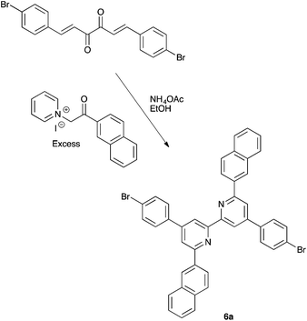 |
| | Scheme 4 Synthesis of the precursor 4,4′-bis(4-bromophenyl)-6,6′-di(naphthalen-2-yl)-2,2′-bipyridine, 6a, by Krönhke methodology. | |
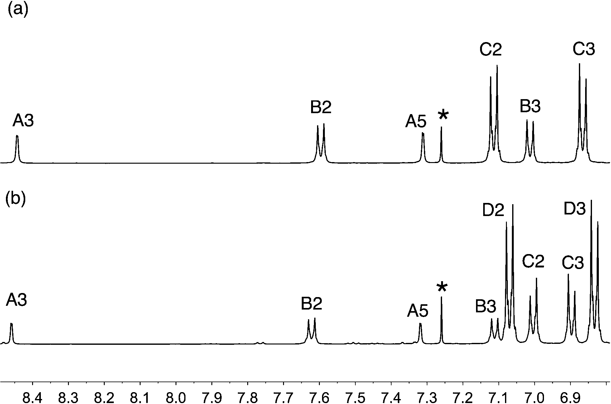
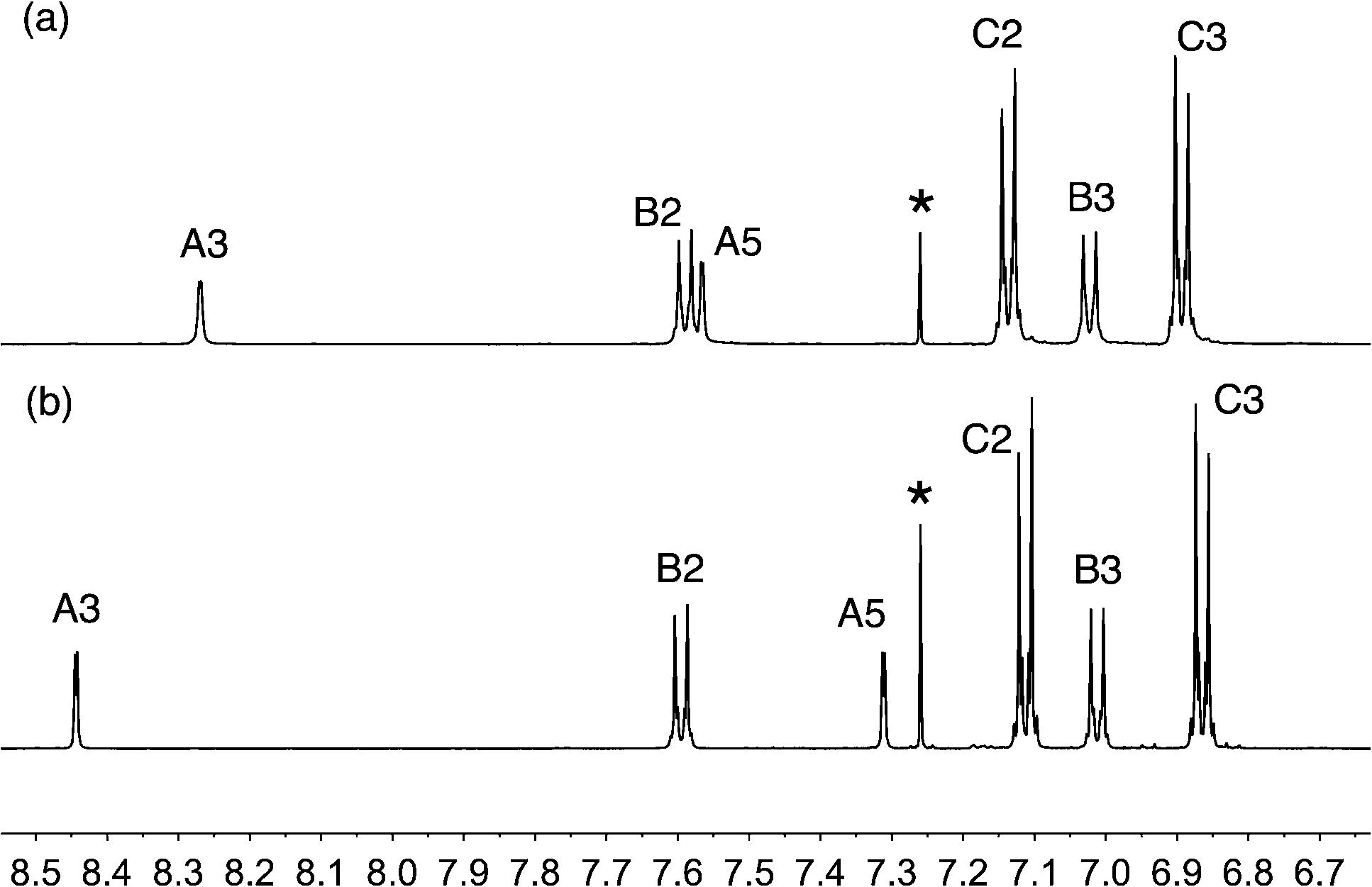
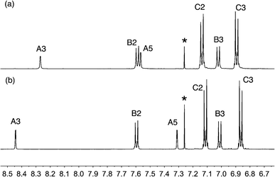
The reactions shown in Scheme 2 proceeded smoothly to give, after purification, the first-generation ligands 2–5 in >85% and 6 in 60%. Yields for the second-generation compounds 8–12 ranged from 65 to 81%. All the ligands are readily soluble in CHCl3 and CH2Cl2. The electrospray mass spectrum of each of 2–6 exhibited a base peak assigned to [M + H]+. For the second-generation ligands, peaks were observed for [M + 2H]2+ and, for 9 and 12, an additional peak arising from [M + H]+.† The 1H and 13C NMR spectra of CDCl3 solutions of the compounds were assigned by 2D techniques. The spectra† indicate a symmetrical bpy domain and signal integrals are consistent with the bis-functionalized structures shown in Scheme 2. Representative spectra for a pair of first- and second-generation ligands are shown in Fig. 1.
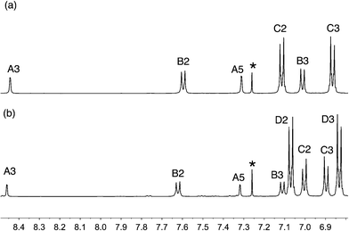 |
| | Fig. 1 Aromatic region of the 500 MHz 1H NMR spectra (CDCl3, 295 K) of (a) first-generation 4 and (b) second-generation 10. See Scheme 2 and ESI† for ring labelling. * = residual CHCl3. | |
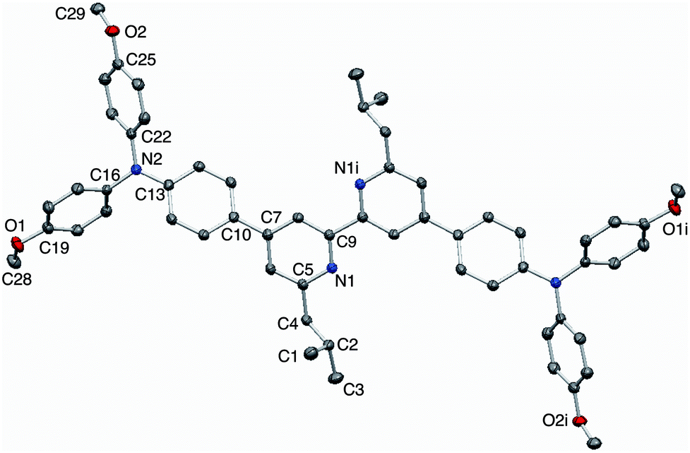
X-Ray quality single crystals of 3 were grown by Et2O diffusion into an acetone/chloroform solution of the compound. The structure of 3 is shown in Fig. 2. Selected bond parameters are given in the figure caption. The compound crystallizes in the space group P with half of the molecule in the asymmetric unit; the second half is generated through an inversion centre and the bpy unit necessarily adopts a trans-conformation and is planar. The phenylene unit is twisted 36.7° with respect to the pyridine ring to which it is bonded, thereby minimizing inter-ring H⋯H interactions. Atom N2 is in a planar environment, consistent with delocalization of the lone pair into the arene π-systems. The twisted arrangement of the three arene rings bonded to N2 is expected on steric grounds. The presence of the isobutyl groups prevents face-to-face interactions between bpy domains of neighbouring molecules. Dominant packing interactions involve methoxy CH⋯πpyridine contacts (CH⋯centroid = 2.39 Å) which lead to a centrosymmetric embrace between adjacent molecules (Fig. 3a). These interactions lead to the assembly of hydrogen-bonded chains which slice obliquely through the unit cell (Fig. 3b).
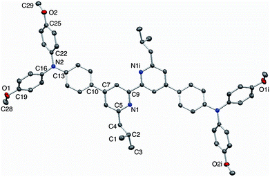 |
| | Fig. 2 Structure of compound 3 with ellipsoids plotted at 50% probability; H atoms omitted for clarity. Symmetry code i = 1 − x, 2 − y, 2 − z. Selected bond parameters: N1–C5 = 1.3451(14), N1–C9 = 1.3453(14), N2–C13 = 1.4006(14), N2–C22 = 1.4262(14), N2–C16 = 1.4302(14), C19–O1 = 1.3649(14), C25–O2 = 1.3697(14), O1–C28 = 1.4225(16), O2–C29 = 1.4274(15) Å; C13–N2–C22 = 121.22(9), C13–N2–C16 = 120.38(9), C22–N2–C16 = 118.16(9), C19–O1–C28 = 117.40(10), C25–O2–C29 = 116.05(9)°. | |
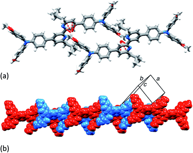 |
| | Fig. 3 (a) Centrosymmetric pair of molecules of 3 embrace through CHOMe⋯πpyridine contacts. (b) The interactions extend between molecules to generate hydrogen bonded chains. | |
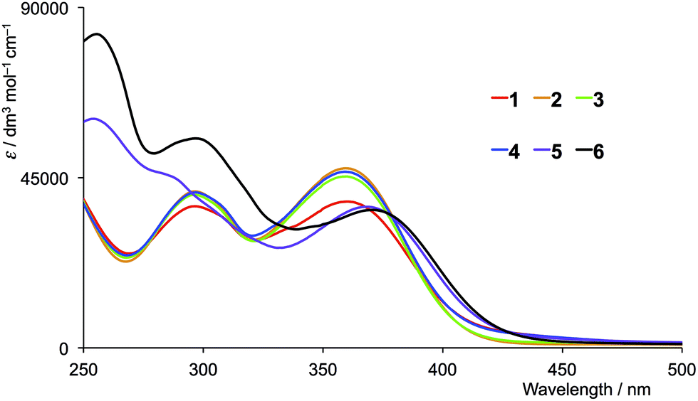
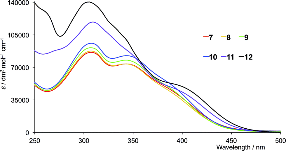
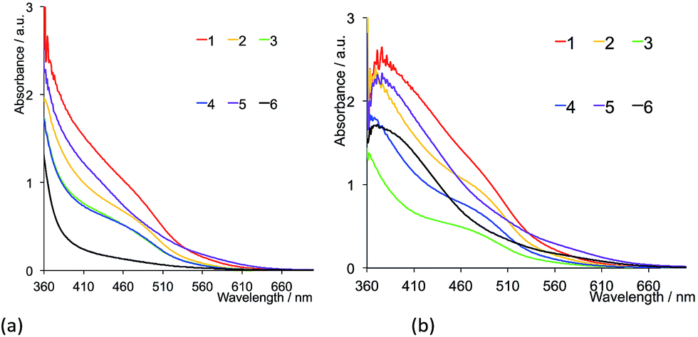
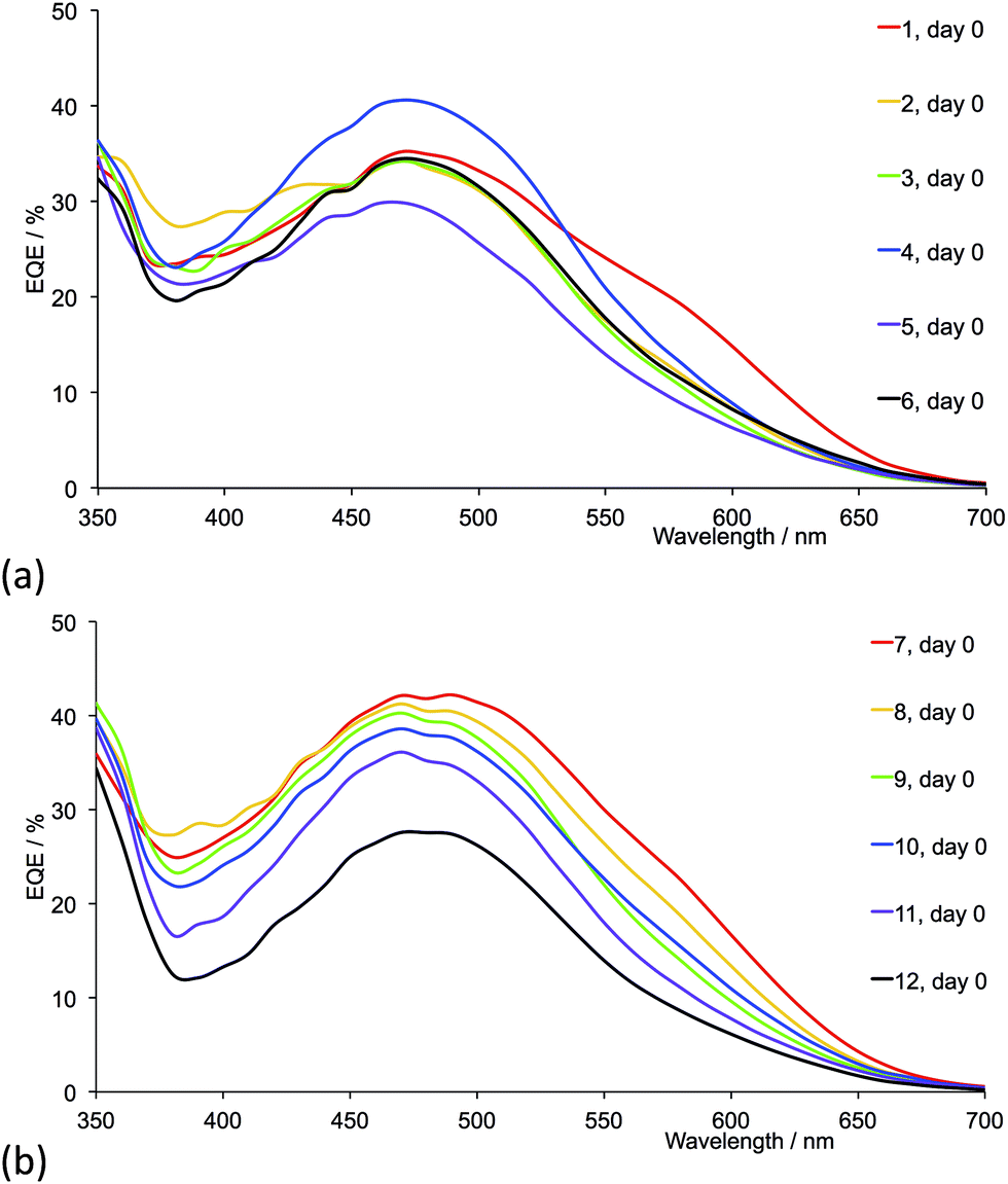
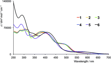
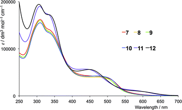
The solution absorption spectra of the first- and second-generation ligands are displayed in Fig. 4 and 5, respectively. The spectra are all broad with intense bands which tail into the visible region. The observed absorptions originate from π* ← π and π* ← n transitions, and the spectra of 1–4 (which contain 6- and 6′-alkyl substituents) are similar, as are those of the second-generation ligands 7–10. Extension of the aromatic domains on going from 1 to 7 (both with methyl substituents) leads to the anticipated increase in extinction coefficient (red curves in Fig. 4 and 5). Similar trends are observed upon comparing the spectra of 2 and 8, 3 and 9, or 4 and 10. As expected, the intensities of the highest energy bands in the spectra of 5 and 11 (phenyl substituents, purple curves in Fig. 4 and 5) and 6 and 12 (naphthyl substituents, black curves in Fig. 4 and 5) are substantially larger than those of the alkyl-substituted ligands.
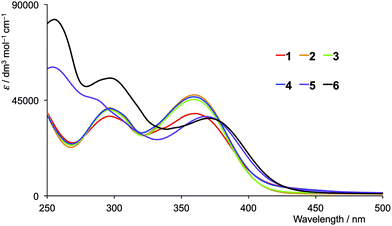 |
| | Fig. 4 Solution absorption spectra of the first-generation ligands 1–6 in CH2Cl2 (1 × 10⁻⁵ mol dm−3). | |
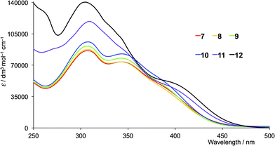 |
| | Fig. 5 Solution absorption spectra of the second-generation ligands 7–12 in CH2Cl2 (1 × 10⁻⁵ mol dm−3). | |
Synthesis and characterization of homoleptic copper(I) complexes
We have previously reported the syntheses and properties of [Cu(1)2][PF6] and [Cu(7)2][PF6].8 Homoleptic copper(I) complexes containing ligands 2–6 and 8–12 were prepared by treatment of [Cu(NCMe)4][PF6] with two equivalents of the appropriate ligand. Yields of [CuL2][PF6] were typically high. The electrospray mass spectra of the complexes containing the first-generation ligands 2–6 each exhibited a peak envelope corresponding to [M − PF6]+ with the correct isotopic pattern. In addition, peaks assigned to [3 + H]+, [4 + H]+, [5 + H]+ or [6 + H]+ were observed in the spectra of the respective complexes. Ligand loss was observed in the mass spectra of the complexes with the second-generation ligands and the spectra exhibited peaks for [CuL]+ and [L + H]+ for L = 8, 9, 10, 11 or 12. For L = 9, 11 and 12, a peak envelope arising from [M − PF6]+ was also observed.
The 1H and 13C NMR spectra of [CuL2][PF6] with L = 2–6 were recorded in CDCl3, making the spectra directly comparable with those of the free ligands. Although the complexes containing the second-generation ligands are soluble in CDCl3, signals in the 1H NMR spectra were broadened, necessitating a solvent change to CD2Cl2 to obtain well-resolved spectra. Fig. 6 compares the aromatic regions of the 1H NMR spectra of 2 and [Cu(2)2][PF6]. Shifts in the signals for HA3 and HA5 are consistent with the change in conformation of the bpy unit upon coordination. Resonances for the peripheral dendron protons are essentially unaffected; the signal for the OMe protons appears at δ 3.82 ppm in 2 and at δ 3.83 ppm in [Cu(2)2][PF6]. The trends are typical of the spectra of all ligand–complex pairs in which the ligand bears 6- and 6′-alkyl substituents (Table 1). The shift to lower frequency for HA3 on comparing ligand with complex (Table 1) is more pronounced for ligands 5 and 11 (phenyl substituents) than for the pairs of alkyl-substituted ligands, and is even more so for 6 and 12 (2-naphthyl substituents). The structure of [Cu(6)2]+ modelled using Spartan 14 (v. 1.1.3, MMFF level) is shown in Fig. 7. The HA3 protons on one bpy ligand are located within a cleft between the two naphthyl domains of the second ligand and thus lie in the shielding region of their ring currents. The same effect is observed for both first- and second-generation ligands and their complexes (Table 1).
 |
| | Fig. 6 Aromatic region of the 500 MHz 1H NMR spectra (CDCl3, 295 K) of (a) [Cu(2)2][PF6] and (b) free ligand 2. See Scheme 2 and ESI† for ring labelling. * = residual CHCl3. | |
Table 1 Comparison of chemical shifts of bpy protons HA3 and HA5 in free ligand, L, in CDCl3 and [CuL2][PF6] complexes in CDCl3 for L = 1–6 and CD2Cl2 for L = 7–12
| L |
HA3 in L |
HA5 in L |
HA3 in [CuL2]+ |
HA5 in [CuL2]+ |
| First-generation |
| 1 |
8.39 |
7.33 |
8.25 |
7.59 |
| 2 |
8.44 |
7.31 |
8.27 |
7.57 |
| 3 |
8.46 |
7.28 |
8.27 |
7.52 |
| 4 |
8.44 |
7.31 |
8.26 |
7.56 |
| 5 |
8.82 |
7.95 |
7.95 |
7.61 |
| 6 |
8.89 |
8.11 |
7.32 |
7.57 |
| |
| Second-generation |
| 7 |
8.40 |
7.33 |
8.26 |
7.57 |
| 8 |
8.46 |
7.32 |
8.34 |
7.60 |
| 9 |
8.46 |
7.28 |
8.35 |
7.56 |
| 10 |
8.46 |
7.32 |
8.34 |
7.61 |
| 11 |
8.83 |
7.96 |
8.02 |
7.66 |
| 12 |
8.93 |
8.12 |
7.43 |
7.60 |
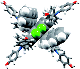 |
| | Fig. 7 Modelled structure of [Cu(6)2]+. The HA3 protons (in green) and bpy domain of one ligand and the two 2-naphthyl groups of the second ligand are shown in space-filling representation. | |
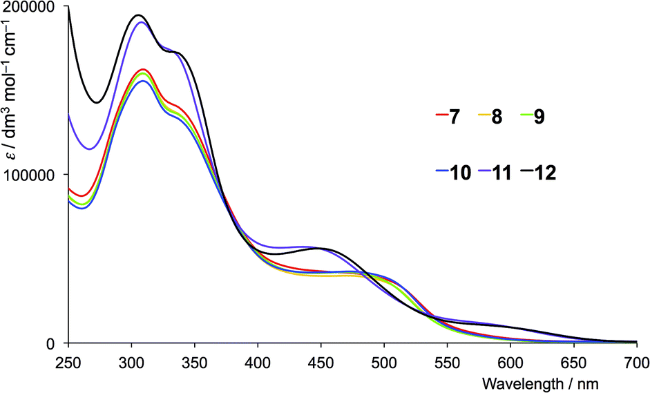
The absorption spectra of CH2Cl2 solutions of the copper(I) complexes are shown in Fig. 8 (first-generation ligands) and Fig. 9 (second-generation). The broad absorption bands extend significantly further to longer wavelength than for the free ligands. The approximate doubling of the extinction coefficients on comparing the spectra of ligands with complexes is consistent with the homoleptic complexes [CuL2]+. At high energies (λ < 450 nm), the absorption spectra of [CuL2]+ for L = 1–6 possess similar band-shapes to those of the first-generation ligands 1–6 (compare Fig. 8 with Fig. 4). The ligand-centred band at ≈360 nm undergoes a red-shift of 10–30 nm on going from ligand to complex. The shoulder at around 480 nm in the spectra of [CuL2]+ for L = 1–4 is absent in the spectra of the ligands and is assigned to the MLCT band. The energy is consistent with the band at 483 nm observed in [Cu(6,6-Me2bpy)2]+, the MLCT character of which has been confirmed from TD-DFT calculations.20 For [Cu(5)2][PF6] and [Cu(6)2][PF6], a low intensity band at 560 and 576 nm, respectively, (Fig. 8) is assumed to arise from the MLCT. The absorption spectra of [CuL2]+ for second-generation ligands 7–12 are dominated by high energy bands originating from ligand-based π* ← π and π* ← n transitions (Fig. 9). Broad shoulders in the spectra of CH2Cl2 solutions of [Cu(7)2][PF6], [Cu(8)2][PF6], [Cu(9)2][PF6] and [Cu(10)2][PF6] centred around 480 nm are assigned to MLCT transitions. (Note that the previously reported spectrum for [Cu(7)2][PF6] with λmax = 505 nm was recorded in MeCN.)8 The MLCT bands for [Cu(11)2][PF6] and [Cu(12)2][PF6] are assigned to the low intensity absorption maxima at 580 nm (Fig. 9), consistent with the first-generation analogues (Fig. 8). The broad and intense spectral responses of all the complexes, especially those containing ligands 7–12, suggest that they should be good candidates as precursors to dyes in DSCs.
 |
| | Fig. 8 Solution absorption spectra of in CH2Cl2 solutions of (1 × 10⁻⁵ mol dm−3) [CuL2][PF6] where L = 1–6 (first-generation ligands). | |
 |
| | Fig. 9 Solution absorption spectra of in CH2Cl2 solutions of (1 × 10⁻⁵ mol dm−3) [CuL2][PF6] where L = 7–12 (second-generation ligands). | |
Electrochemistry
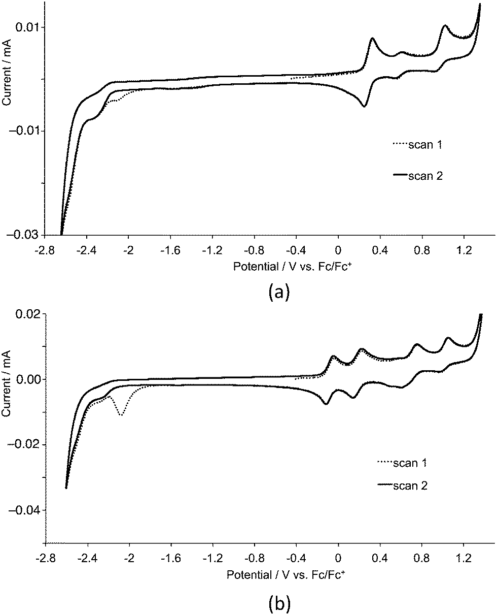
Cyclic voltammetric data for the homoleptic copper(I) complexes are presented in Table 2. Cyclic voltammograms were recorded CH2Cl2 to preclude association of the metal ion with coordinating solvents,21 and are always referenced to internal ferrocene. For the first- or second-generation complexes, three or five oxidation processes are observed, respectively. A representative pair of CVs for first-generation [Cu(3)]2][PF6] and second-generation [Cu(9)2][PF6] is shown in Fig. 10. By comparison with related systems, the oxidation process in the range 0.40–0.58 V is assigned to the Cu+/Cu2+ couple. In copper(I) diimine complexes, incorporation of substituents ortho to the N-donor sites (e.g. 6,6′-positions in bpy) stabilizes tetrahedral Cu+ with respect to square-planar copper(II) by sterically encumbering the flattening of the coordination environment. The potentials for the Cu+/Cu2+ couple in [CuL2][PF6] with L = 1–6 follow the same trend as in the series [CuL2][PF6] with L = 7–12. The complexes containing the phenyl or 2-naphthyl substituents (ligands 5, 6, 11 and 12) exhibit the lowest metal oxidation potentials, followed by the complexes containing the methyl substituents (ligands 1 and 7). The metal-centred oxidation in [Cu(2)2][PF6], [Cu(3)2][PF6], [Cu(4)2][PF6], [Cu(8)2][PF6], [Cu(9)2][PF6] and [Cu(10)2][PF6] (n-butyl, isobutyl or n-hexyl substituents) occurs at similar potentials (+0.56 ± 0.02 V), noticeably higher than in the methyl, phenyl or 2-naphthyl-containing complexes. The trends are consistent with data for [CuL2][PF6] with L = 4,4′-bis(4-bromophenyl)-6,6′-dialkyl-2,2′-bipyridines (alkyl = Me, nBu, isoBu, nhexyl) or bis(4-bromophenyl)-6,6′-diphenyl-2,2′-bipyridine.10 For the alkyl substituents, the trend follows the steric bulk of the group, with the complexes containing the least sterically demanding substituents being the easiest to oxidize. We have previously commented10 that the metal centre in [CuL2]+ with L = 4,4′-bis(4-bromophenyl)-6,6′-diphenyl-2,2′-bipyridine possesses a flattened geometry in the solid state as a consequence of π-stacking of 6-phenyl groups of one ligand and the bpy domain of the other. This leads to entatic22 lower energy metal oxidation as the coordination geometry is already enroute to that favoured by Cu2+.
Table 2 Cyclic voltammetric data for [CuL2][PF6] with L = 1–12 with respect to Fc/Fc+; CH2Cl2 solutions with [nBu4N][PF6] as supporting electrolyte and scan rate of 0.1 V s−1. Processes are reversible unless otherwise stated (qr = quasi-reversible; ir = irreversible)
| Complex |
E1/2ox/V (Epc − Epa/mV) |
E1/2ox/V (Epc − Epa/mV) |
E1/2ox/V (Epc − Epa/mV) |
E1/2ox/V (Epc − Epa/mV) |
E1/2ox/V (Epc − Epa/mV) |
E1/2red/V (Epc − Epa/mV) |
| 1st and 2nd oxidation processes overlap. |
| [Cu(1)2][PF6] |
|
+0.29 (96) |
+0.44 (87) |
|
+1.00ir |
−2.04ir |
| [Cu(2)2][PF6] |
|
+0.29 (79) |
+0.57 (65) |
|
+0.98 (94) qr |
−2.09ir |
| [Cu(3)2][PF6] |
|
+0.29 (86) |
+0.58 (66) |
|
+0.99 (102)qr |
−2.07ir |
| [Cu(4)2][PF6] |
|
+0.29 (89) |
+0.57 (74) |
|
+0.96 (106)qr |
−2.08ir |
| [Cu(5)2][PF6] |
|
+0.32a |
+0.40a |
|
+0.99 (83)qr |
−2.25ir |
| [Cu(6)2][PF6] |
|
+0.31a |
+0.40a |
|
+0.97 (96)qr |
−2.07ir |
| [Cu(7)2][PF6] |
−0.07 (78) |
+0.20 (75) |
+0.47 (129) |
+0.69 (168) |
+1.03ir |
−2.03ir |
| [Cu(8)2][PF6] |
−0.07 (83) |
+0.19 (83) |
+0.54 (99) |
+0.69 (155) |
+1.01 (111)qr |
−2.07ir |
| [Cu(9)2][PF6] |
−0.08 (65) |
+0.18 (88) |
+0.55 (90) |
+0.68 (157) |
+1.02 (85)qr |
−2.06ir |
| [Cu(10)2][PF6] |
−0.07 (79) |
+0.18 (89) |
+0.55 (84) |
+0.69 (150) |
+1.03 (86)qr |
−2.06ir |
| [Cu(11)2][PF6] |
−0.07 (81) |
+0.19 (103) |
+0.39(81) |
+0.69 (170) |
+1.03 (69)qr |
−2.19ir |
| [Cu(12)2][PF6] |
−0.08 (63) |
+0.19 (85) |
+0.39 (67) |
+0.68 (168) |
+1.02ir |
−2.08ir |
 |
| | Fig. 10 Cyclic voltammograms of CH2Cl2 (degassed) solutions of (a) [Cu(3)2][PF6] and (b) [Cu(9)2][PF6] for first- and second cycles. Scan rate = 0.1 V s−1. | |
For complexes containing the first-generation ligands, a ligand-based oxidation process is observed close to +0.30 V similar to that observed in the free ligand.8 For [CuL2][PF6] complexes with second-generation ligands 7–12, four ligand-centred oxidation processes are observed in each complex (Table 2), again assigned by analogy with the free ligand.8 The potential for each ligand oxidation process shows little variation across the series [Cu(7)2][PF6] to [Cu(12)2][PF6].
Ligand reduction processes in the complexes lie close to the edge of the solvent accessible window and are typically poorly defined. Each complex exhibits an irreversible reduction process close to −2.05 V which appears only in the first cycle (Fig. 10).
DSC fabrication and solid-state absorption spectra
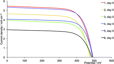
Heteroleptic dyes for DSC measurements were assembled by stepwise adsorption of anchoring ligand 13 onto commercial titania electrodes followed by treatment with a solution of the labile23,24 homoleptic complexes [CuL2][PF6] (L = 1 to 12). Ligand exchange occurs with the formation of surface-bound heteroleptic dyes (Scheme 5). Our strategy for surface-immobilized dye assembly8–10,20 has recently been employed by Robertson and coworkers.25 In the present study, we observed that dye uptake is dependent on the solvent used during the dipping process. Fig. 11 shows the appearance of DSCs which have been assembled using CH2Cl2 or acetone solutions of [CuL2][PF6] (L = 1 to 12). In every pair of CH2Cl2/acetone dipped cells, the intensity of colour was reproducibly greater for the acetone-dipping.
 |
| | Scheme 5 Anchored heteroleptic dyes. For the first-generation, Ar = 4-MeOC6H4 in ligands 1–6 (see Scheme 2); for the second-generation, Ar = 4-MeOC6H4 in ligands 7–12 (see Scheme 2). | |
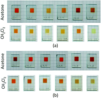 |
| | Fig. 11 Cells after dipping in acetone or CH2Cl2 solutions of the homoleptic complexes: (a) first-generation ligands 1–6 (left to right), (b) second-generation ligands 7–12 (left to right). | |
FTO/TiO2 electrodes (without a scattering layer) with adsorbed dye were prepared and their solid-state absorption spectra recorded, each spectrum being corrected for the background spectrum of a blank electrode. Absorption spectra for electrodes with first-generation dyes made using CH2Cl2 or acetone solutions of the homoleptic complexes [CuL2][PF6] with L = 1–6 are shown in Fig. 12a and b, respectively. For a given ancillary ligand, the general trend is for enhanced absorptivity when acetone is used in the dipping solution during cell fabrication. A similar trend is observed for complexes containing the second-generation ligands 7–12. The enhancement of absorption observed on changing from CH2Cl2 to acetone coupled with that on going from first- to second-generation ligand in the surface-immobilized heteroleptic complex, is exemplified in Fig. 13 with [Cu(13)(4)]+ and [Cu(13)(10)]+.
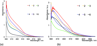 |
| | Fig. 12 Solid-state absorption spectra of electrodes with anchored dyes [Cu(13)(L)]+ where L = 1–6. The electrodes were made using (a) CH2Cl2, or (b) acetone solutions of [CuL2][PF6]. | |
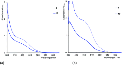 |
| | Fig. 13 Solid-state absorption spectra of electrodes with the anchored first- and second-generation dyes [Cu(13)(4)]+ and [Cu(13)(10)]+. The electrodes with anchored dye were prepared using (a) CH2Cl2, or (b) acetone solutions of [CuL2][PF6] (L = 4 or 10). | |
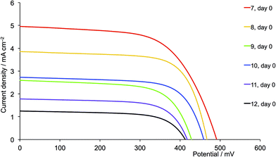
DSC performances: first- versus second-generation ancillary ligands
The enhanced absorption observed using acetone in the dye dipping cycle leads us to initially focus on the performances of these DSCs. All DSCs were masked to avoid overestimation of efficiencies.26 In order to ensure that DSC parameters were reproducible, measurements were made using duplicate cells for each dye-solvent combination. A complete set of DSC parameters is presented in Table S1,† and Table 3 summarizes representative DSC characteristics using anchoring ligand 13, first-generation ancillary ligands and acetone in the dye dipping cycle, measured over a period of three weeks and with respect to the standard dye N719. The final column in the table shows relative efficiencies with respect to N719 set to 100%. Performance data for the dyes containing the second-generation ligands 7–12 are given in Tables 4 and S2.†
Table 3 DSC performance data for sealed and masked cells using anchoring ligand 13 and first-generation ancillary ligands, and acetone in the [CuL2][PF6] dipping cycle. Relative efficiencies (last column) are with respect to 100% for standard dye N719 measured under the same conditions. See also ESI Table S11
| Anchored dye |
JSC/mA cm−2 |
VOC/mV |
ff |
η/% |
Relative η/% |
| For [Cu(13)(1)]+, the second measurements were made after 18 days. |
| On the day of sealing the cell |
| [Cu(13)(1)]+ |
6.00 |
510 |
70.3 |
2.15 |
29.4 |
| [Cu(13)(2)]+ |
4.41 |
482 |
69.4 |
1.48 |
20.2 |
| [Cu(13)(3)]+ |
4.22 |
475 |
69.6 |
1.39 |
19.0 |
| [Cu(13)(4)]+ |
5.60 |
542 |
71.8 |
2.18 |
29.8 |
| [Cu(13)(5)]+ |
3.22 |
468 |
68.6 |
1.03 |
14.1 |
| [Cu(13)(6)]+ |
4.29 |
508 |
67.0 |
1.46 |
19.9 |
| N719 |
16.72 |
641 |
68.4 |
7.32 |
100 |
| |
| 22a days after sealing the cell |
| Anchored dye |
JSC/mA cm−2 |
VOC/mV |
ff |
η/% |
Relative η/% |
| [Cu(13)(1)]+ |
5.27 |
520 |
71.1 |
1.94 |
24.4 |
| [Cu(13)(2)]+ |
4.42 |
516 |
70.7 |
1.61 |
20.3 |
| [Cu(13)(3)]+ |
4.18 |
487 |
69.6 |
1.42 |
17.9 |
| [Cu(13)(4)]+ |
5.05 |
532 |
70.8 |
1.90 |
23.9 |
| [Cu(13)(5)]+ |
4.00 |
485 |
69.9 |
1.36 |
17.1 |
| [Cu(13)(6)]+ |
4.10 |
504 |
68.0 |
1.41 |
17.7 |
| N719 |
16.65 |
671 |
71.2 |
7.95 |
100 |
Table 4 DSC performance data for masked cells using anchoring ligand 13 and second-generation ancillary ligands, and acetone in the [CuL2][PF6] dipping cycle. Relative efficiencies (last column) are with respect to 100% for standard dye N719 measured under the same conditions. See also ESI Table S21
| Anchored dye |
JSC/mA cm−2 |
VOC/mV |
ff |
η/% |
Relative η/% |
| For N719, the second measurement was made after 15 days. |
| On the day of sealing the cell |
| [Cu(13)(7)]+ |
6.46 |
515 |
67.9 |
2.26 |
32.8 |
| [Cu(13)(8)]+ |
6.08 |
506 |
70.8 |
2.18 |
31.6 |
| [Cu(13)(9)]+ |
5.48 |
475 |
69.9 |
1.82 |
26.4 |
| [Cu(13)(10)]+ |
5.25 |
488 |
70.9 |
1.81 |
26.2 |
| [Cu(13)(11)]+ |
4.01 |
459 |
70.2 |
1.29 |
18.7 |
| [Cu(13)(12)]+ |
3.04 |
444 |
69.2 |
0.93 |
13.5 |
| N719 |
16.52 |
608 |
68.8 |
6.90 |
100 |
| |
| 22a days after sealing the cell |
| Anchored dye |
JSC/mA cm−2 |
VOC/mV |
ff |
η/% |
Relative η/% |
| [Cu(13)(7)]+ |
5.94 |
536 |
70.3 |
2.23 |
27.5 |
| [Cu(13)(8)]+ |
5.97 |
532 |
71.6 |
2.27 |
28.0 |
| [Cu(13)(9)]+ |
6.31 |
541 |
71.0 |
2.42 |
29.8 |
| [Cu(13)(10)]+ |
5.47 |
522 |
70.6 |
2.02 |
24.9 |
| [Cu(13)(11)]+ |
4.99 |
487 |
71.3 |
1.73 |
21.3 |
| [Cu(13)(12)]+ |
2.77 |
466 |
70.2 |
0.91 |
11.2 |
| N719 |
16.98 |
674 |
70.9 |
8.11 |
100 |
A comparison of Tables 3 and 4 reveals that, with the exception of [Cu(13)(6)]+ and [Cu(13)(12)]+ (6 and 12 = 6,6′-bis(2-naphthyl) substituted ligands), the dyes containing the second-generation ancillary ligands give higher global efficiencies. This corresponds to an increase in the solid-state absorbance of the DSCs as illustrated in Fig. 12. After three weeks, the DSCs with the ancillary ligands 7–9 and 11 exhibit higher JSC values than those with 1–3 and 5 (Fig. 14, 15, S1 and S2†), while JSC for dyes containing the n-hexyl subtituents (4 and 10) are similar (Fig. S3†). For [Cu(13)(9)]+ (isobutyl substituents, second-generation), there is also a significant gain in VOC over the three week period (Fig. 14). The dyes with the methyl (Fig. 15) or n-butyl (Fig. S1†) substituents perform the best, with enhancement on going from first- to second-generation ancillary ligands. [Cu(13)(1)]+ and [Cu(13)(7)]+ (methyl substituted ancillary ligands) suffer from reduced JSC as the DSCs age, but benefit from increased VOC. This latter enhancement is also observed in [Cu(13)(2)]+ and [Cu(13)(8)]+ (n-butyl groups).
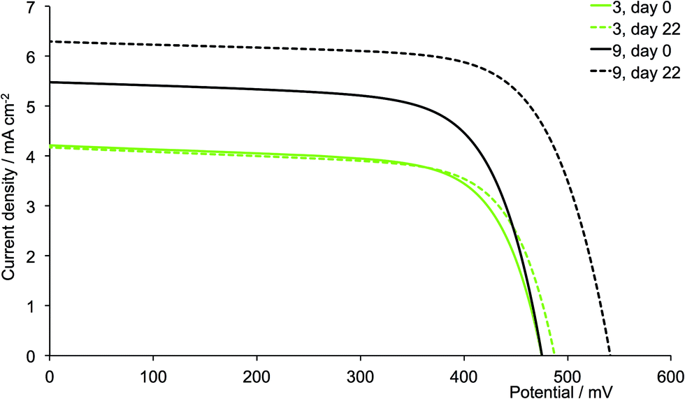
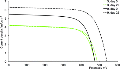 |
| | Fig. 14 J–V curves for dyes [Cu(13)(3)]+ and [Cu(13)(9)]+ (isobutyl substituents, acetone used in the dye-dipping cycle) on day of sealing the DSC (day 0) and after 18 or 22 days showing enhancement of JSC with second-generation ligand. | |
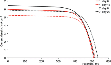 |
| | Fig. 15 J–V curves for dyes [Cu(13)(1)]+ and [Cu(13)(7)]+ (methyl substituents, acetone used in the [CuL2][PF6] dipping cycle) on day of sealing the DSC (day 0) and after 18 or 22 days. | |
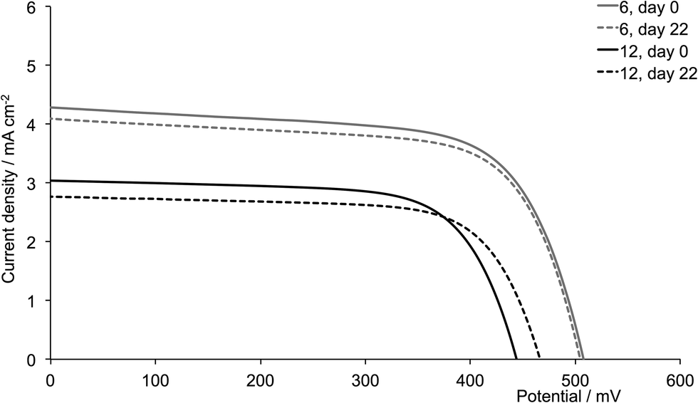
The dyes which incorporate the sterically hindering 2-naphthyl groups exhibit poorer device performances than the other dyes, and this is associated with lower JSC values (Fig. 16). As the DSCs age, the efficiencies decrease, with this trend observed for both generations of ligands; these observations are confirmed for the duplicate DSCs (Tables S1 and S2†). The data also suggest that extending the dendron on going from 6 to 12 is detrimental to overall dye performance (Fig. 16).
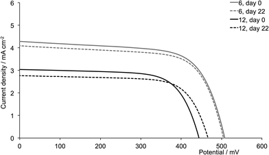 |
| | Fig. 16 J–V curves for dyes [Cu(13)(6)]+ and [Cu(13)(12)]+ (naphthyl substituents, acetone used in the [(CuL)2][PF6] dipping cycle) on day of sealing the DSC (day 0) and after 22 days. | |
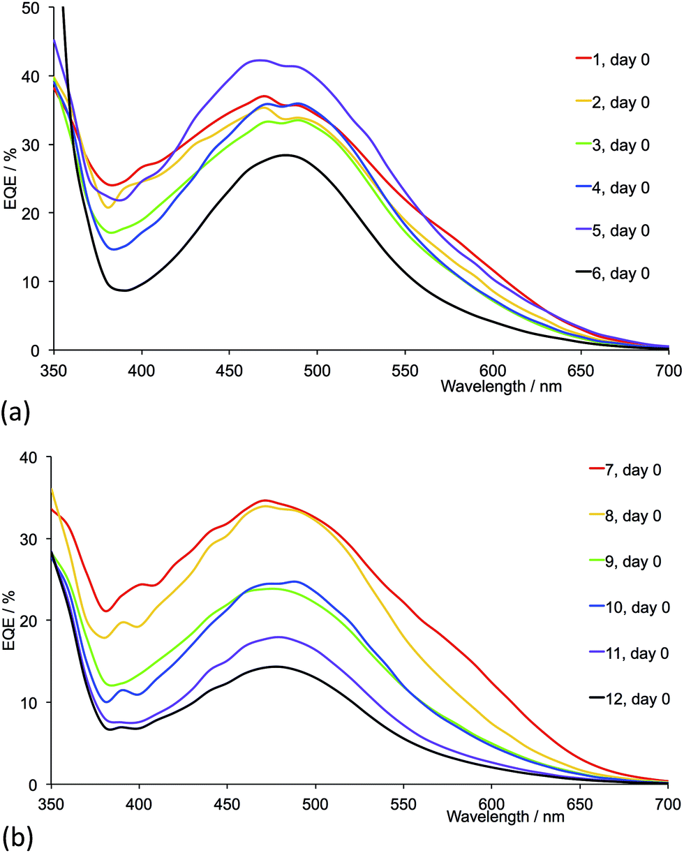
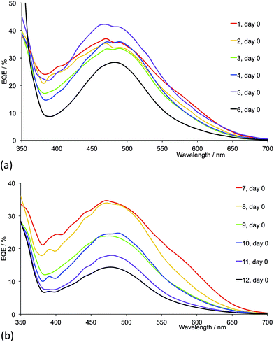
Fig. 17 shows the EQE spectra of freshly sealed DSCs for all the dyes; the spectra were also recorded after 22 days (Fig. S4 and S5†). Only small changes in EQE parameters (Tables 5 and 6) are observed for a given DSC over a 22 day period. Except for 2-naphthyl-containing dyes, on going from the first- to second-generation ligand in each pair (e.g. [Cu(13)(1)]+ to [Cu(13)(7)]+), values of EQEmax typically increase. Irrespective of the ancillary ligand, the dyes exhibit values of λmax in the range 470–490 nm. For the dye containing 1 (methyl groups), Fig. 17a shows a pronounced low energy shoulder at 590 nm, confirming improved photoresponse and electron injection consistent with the relatively high conversion efficiency observed for anchored dye [Cu(13)(1)]+ (Table 4). The dyes with the second-generation alkyl-functionalized ancillary ligands all exhibit enhanced EQE to lower energies than the first-generation analogues (Fig. 17b versus 17a). This observation appears not to carry through to dyes 5 and 11 with phenyl substituents where there is little gain in EQE at higher wavelength upon extending the hole transport domain. Consistent with the earlier discussion, EQE data confirm poorer electron injection on going from 6 to 12 (naphthyl-groups).
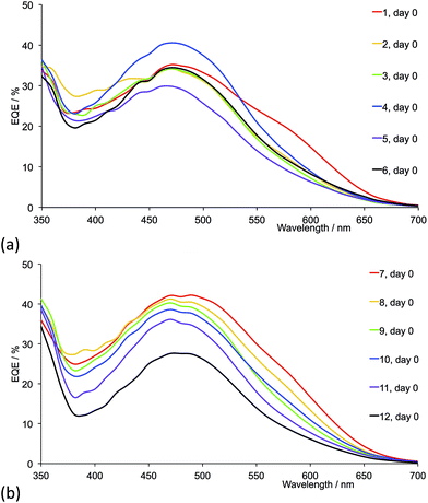 |
| | Fig. 17 EQE spectra (on the day of sealing) of DSCs with dyes containing ancillary ligands (a) 1–6 and (b) 7–12. Acetone was used in the [CuL2][PF6] dipping cycle. | |
Table 5 EQE maxima for DSCs containing first-generation dyes
| Anchored dye |
Day 0 |
Day 22 |
| λmax/nm |
EQEmax/% |
λmax/nm |
EQEmax/% |
| [Cu(13)(1)]+ |
470 |
35.2 |
470 |
31.3 |
| [Cu(13)(2)]+ |
470 |
34.4 |
470 |
32.8 |
| [Cu(13)(3)]+ |
470 |
34.2 |
470 |
32.0 |
| [Cu(13)(4)]+ |
470 |
40.6 |
470 |
37.2 |
| [Cu(13)(5)]+ |
470 |
29.0 |
470 |
32.7 |
| [Cu(13)(6)]+ |
470 |
35.0 |
470 |
31.2 |
Table 6 EQE maxima for DSCs containing second-generation dyes
| Anchored dye |
Day 0 |
Day 22 |
| λmax/nm |
EQEmax/% |
λmax/nm |
EQEmax/% |
| [Cu(13)(7)]+ |
470-490 |
42.2 |
480 |
41.8 |
| [Cu(13)(8)]+ |
470 |
41.3 |
470 |
41.7 |
| [Cu(13)(9)]+ |
470 |
40.3 |
470 |
46.5 |
| [Cu(13)(10)]+ |
470 |
38.6 |
480 |
41.3 |
| [Cu(13)(11)]+ |
470 |
36.1 |
480 |
41.4 |
| [Cu(13)(12)]+ |
460-470 |
27.6 |
470 |
24.3 |
DSC performances: influence of solvent in the dye dipping cycles
We now return to the influence of the solvent during the dye dipping cycle when making the solar cells. Tables S3 and S4† give DSC parameters for cells (including duplicates) which were fabricated using CH2Cl2 solutions of the homoleptic dyes. Measurements were made over a three week period and Fig. S6 and S7† summarize the J–V characteristics. Data for the best performing cells on the day of sealing are presented in Table 7, and Fig. 18 and 19 show J–V curves for the first- and second-generation dyes, respectively. A comparison of the data in Table 7 with those in Tables 3 and 4 indicates that, in general, the conversion efficiencies are higher when acetone is used during cell fabrication. It is difficult to see unambiguous trends between the DSC performances and the 6,6′-substituents in the ancillary ligand. However, in all cases, the dyes containing the methyl substituents perform well. The worst performing dyes contain the bulky 2-naphthyl groups, irrespective of solvent, and the EQE spectra in Fig. 17 and 20 confirm the poorest electron injection as a function of wavelength for dyes with ligands 6 and 12.
Table 7 DSC performance data for masked cells using anchoring ligand 13 and first or second-generation ancillary ligands, and CH2Cl2 in the [CuL2][PF6] dipping cycle. Relative efficiencies (last column) are with respect to 100% for standard dye N719 measured under the same conditions. See also ESI Tables S3 and S41
| Anchored dye |
JSC/mA cm−2 |
VOC/mV |
ff |
η/% |
Relative η/% |
| First-generation ligands; on the day of sealing the cell |
| [Cu(13)(1)]+ |
5.47 |
490 |
69.4 |
1.86 |
25.1 |
| [Cu(13)(2)]+ |
4.65 |
475 |
69.8 |
1.54 |
20.8 |
| [Cu(13)(3)]+ |
3.94 |
479 |
69.6 |
1.31 |
17.7 |
| [Cu(13)(4)]+ |
4.07 |
491 |
71.8 |
1.43 |
19.3 |
| [Cu(13)(5)]+ |
5.35 |
492 |
70.4 |
1.85 |
25.0 |
| [Cu(13)(6)]+ |
2.94 |
485 |
68.3 |
0.97 |
13.1 |
| N719 |
16.31 |
637 |
71.3 |
7.41 |
100.0 |
| |
| Second-generation ligands; on the day of sealing the cell |
| Anchored dye |
JSC/mA cm−2 |
VOC/mV |
ff |
η/% |
Relative η/% |
| [Cu(13)(7)]+ |
4.32 |
509 |
68.1 |
1.50 |
20.3 |
| [Cu(13)(8)]+ |
4.08 |
469 |
67.9 |
1.30 |
17.6 |
| [Cu(13)(9)]+ |
2.60 |
428 |
65.3 |
0.73 |
9.9 |
| [Cu(13)(10)]+ |
2.73 |
459 |
68.5 |
0.86 |
11.6 |
| [Cu(13)(11)]+ |
1.78 |
418 |
67.2 |
0.50 |
6.8 |
| [Cu(13)(12)]+ |
1.63 |
411 |
61.1 |
0.41 |
5.5 |
| N719 |
16.44 |
647 |
69.5 |
7.40 |
100.0 |
 |
| | Fig. 18 J–V curves for dyes [Cu(13)(L)]+ with L = 1–6 on day of sealing the DSCs (day 0). CH2Cl2 was used in the [CuL2][PF6] dipping cycle. | |
 |
| | Fig. 19 J–V curves for dyes [Cu(13)(L)]+ with L = 7–12 on day of sealing the DSCs (day 0). CH2Cl2 was used in the [CuL2][PF6] dipping cycle. | |
 |
| | Fig. 20 EQE spectra (on the day of sealing) of DSCs with dyes containing ligands (a) 1–6 and (b) 7–12. CH2Cl2 was used in the [CuL2][PF6] dipping cycle. | |
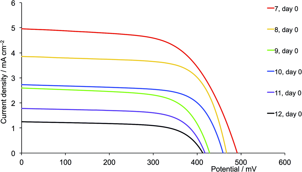
For the second-generation dyes (Fig. 19), the DSC performance corresponds quite well to the steric demands of the 6,6′-substituents, the best VOC, JSC and η values being observed when methyl groups are used. The EQE spectra for these dyes (Fig. 20b) are also consistent with this performance ordering, and we again (compare red curves in Fig. 17b and 20b) observe extension of the EQE spectrum of the dye containing 7 to lower energy compared to the remaining dyes.
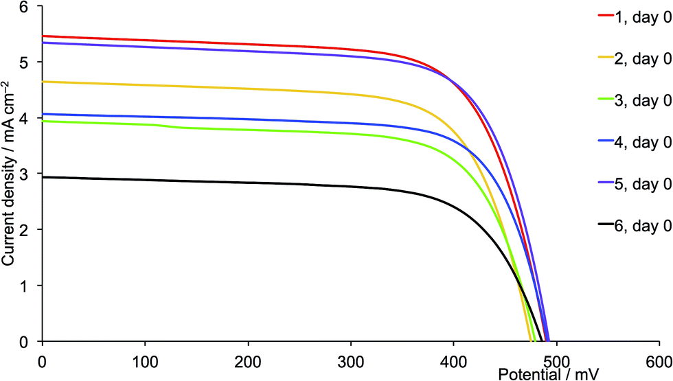
One of the most dramatic differences between performances of DSCs assembled using acetone or CH2Cl2 copper(I) complex solutions is seen with the 6,6′-diphenyl substituted ancillary ligands. The performance of DSCs containing [Cu(13)(5)]+ (first-generation, phenyl) improves when CH2Cl2 is used instead of acetone. For the CH2Cl2-derived dyes, a ripening effect is observed (Table S3†) with η increasing from 1.85 to 2.06% (25.0 to 26.0% relative to N719), mainly due to an increase in VOC from 492 to 537 mV (Fig. S6†). For the CH2Cl2 dye solutions, [Cu(13)(5)]+ is the optimum dye. However, extending the hole transporting domain appears to be unfavourable with losses in both VOC and JSC (Fig. 18 versus 19, purple curves). The values of EQEmax are 42.2% (at λmax = 470 nm) for [Cu(13)(5)]+ and 18.0% (at λmax = 480 nm) for [Cu(13)(11)]+. DSCs with [Cu(13)(5)]+ (first-generation, phenyl) show similar values of VOC , JSC and η to those with [Cu(13)(1)]+ (first-generation, methyl). We attribute the loss in performance on going from [Cu(13)(5)]+ to [Cu(13)(11)]+ to dye aggregation arising from intermolecular interactions involving the phenyl substituents and dendron in the second-generation 11.
Conclusions
We have prepared and characterized two series of homoleptic [CuL2]+ complexes containing bpy-derived ligands with different 6,6′-substituents, and either first-generation (ligands 1–6) or second-generation (ligands 7–12) hole transporting dendrons. FTO/TiO2 electrodes were functionalized with the phosphonic acid 13. Ligand exchange using either CH2Cl2 or acetone solutions of [CuL2]+ gave two series of surface-bound heteroleptic dyes. Solid-state absorption spectra of dye-covered electrodes show that uptake of the dye is improved if acetone rather than CH2Cl2 is used in the dye-dipping cycle.
When acetone is used in the dye-soaking process, the best DSC efficiencies are obtained using the second generation dyes except for those with 2-naphthyl groups where low JSC values contribute to a poor performance. The enhancement on going from first- to second-generation dendron is consistent with increased absorbance in the solid-state absorption spectra. The dyes that perform most efficiently, both for first and generation-ancillary ligands, are those with the methyl or n-butyl substituents. The EQE spectra of the DSCs containing the methyl-containing ancillary ligands show extension of the band to lower energy, consistent with electron injection over a wider range of wavelengths compared to the other dyes.
Overall, the DSC performances for cells made using acetone in the dye-dipping cycle are better than those made using CH2Cl2 solutions. For dyes assembled in CH2Cl2, those with ancillary ligands 1 and 7 (methyl groups) perform well, and exhibit the highest VOC, JSC and η values as well as EQE spectra that extend further towards higher wavelengths than the other dyes. The EQE spectra indicate that dyes containing the 2-naphthyl groups in Lancillary show the poorest electron injection, consistent with low JSC values. We conclude that incorporation of these large aromatic substituents is detrimental to DSC performance. In contrast, the first-generation 6,6′-diphenyl-substituted ancillary ligand, 5, gives a dye that performs as well as that containing 1 (methyl groups), and for CH2Cl2-derived dyes, [Cu(13)(5)]+ is the optimum dye. However, the performance dramatically falls on going to the second-generation analogue 11.
Our overall conclusions are as follows. Among the [Cu(13)(Lancillary)]+ dyes studied, the most promising Lancillary ligands are 1 and 5 (methyl or phenyl substituents) if CH2Cl2 is used in the dye-dipping cycle. Generally, acetone is favoured over CH2Cl2 in the dye-assembly process, and gives adsorbed dyes that exhibit higher absorbances in the solid-state absorption spectra and enhanced conversion efficiencies. Use of the bulky 2-naphthyl substituents militates against good DSC performance. We will report on the effects of adding the co-adsorbant cheno to these DSC systems in the near future.
Acknowledgements
The European Research Council (Advanced Grant 267816 LiLo), Swiss National Science Foundation and University of Basel are acknowledged for financial support. Cathrin Ertl, Roché Walliser and Dr Colin Martin are thanked for recording 500 NMR spectra, and Dr Collin Morris is acknowledged for recording the SEM image at the ZMB (University of Basel).
Notes and references
- G. C. Vougioukalakis, A. I. Philippopoulos, T. Stergiopoulos and P. Falaras, Coord. Chem. Rev., 2011, 255, 2602 Search PubMed , and references therein.
- N. Armaroli, Chem. Soc. Rev., 2001, 30, 113 Search PubMed.
- N. Armaroli, Top. Curr. Chem., 2007, 280, 69 CrossRef CAS.
- N. Alonso-Vante, J-F. Nierengarten and J.-P. Sauvage, J. Chem. Soc. Dalton Trans., 1994, 1650 Search PubMed.
- N. Robertson, ChemSusChem, 2008, 1, 977 CrossRef CAS PubMed.
- B. Bozic-Weber, E. C. Constable and C. E. Housecroft, Chem. Soc. Rev., 2013, 257, 3089 CAS.
- M. Sandroni, L. Favereau, A. Planchat, H. Akdas-Kilig, N. Szuwarski, Y. Pellegrin, E. Blart, H. Le Bozec, M. Boujtita and F. Odobel, J. Mater. Chem. A, 2014, 2, 9944 CAS.
- B. Bozic-Weber, S. Brauchli, E. C. Constable, S. O. Fürer, C. E. Housecroft and I. A. Wright, Phys. Chem. Chem. Phys., 2013, 15, 4500 RSC.
- B. Bozic-Weber, E. C. Constable, C. E. Housecroft, P. Kopecky, M. Neuburger and J. A. Zampese, Dalton Trans., 2011, 40, 12584 RSC.
- B. Bozic-Weber, S. Y. Brauchli, E. C. Constable, S. O. Fürer, C. E. Housecroft, F. J. Malzner, I. A. Wright and J. A. Zampese, Dalton Trans., 2013, 42, 12293 Search PubMed.
- G. J. Kubas, Inorg. Synth., 1990, 28, 68 CrossRef CAS PubMed.
- Bruker Analytical X-ray Systems, Inc., APEX2, version 2 User Manual, M86-E01078, Madison, WI, 2006 Search PubMed.
- G. M. Sheldrick, Acta Crystallogr., Sect. A: Cryst. Phys., Diffr., Theor. Gen. Crystallogr., 2008, 64, 112 CrossRef CAS PubMed.
- I. J. Bruno, J. C. Cole, P. R. Edgington, M. K. Kessler, C. F. Macrae, P. McCabe, J. Pearson and R. Taylor, Acta Crystallogr., Sect. B: Struct. Sci., 2002, 58, 389 Search PubMed.
- C. F. Macrae, I. J. Bruno, J. A. Chisholm, P. R. Edgington, P. McCabe, E. Pidcock, L. Rodriguez-Monge, R. Taylor, J. van de Streek and P. A. Wood, J. Appl. Crystallogr., 2008, 41, 466 CrossRef CAS.
- S. Ito, P. Chen, P. Comte, M. K. Nazeeruddin, P. Liska, P. Péchy and M. Grätzel, Prog. Photovoltaics, 2007, 15, 603 CAS.
- S. Ito, T. N. Murakami, P. Comte, P. Liska, C. Grätzel, M. K. Nazeeruddin and M. Grätzel, Thin Solid Films, 2008, 516, 4613 CrossRef CAS PubMed.
- F. Krönhke, Synthesis, 1976, 1 CrossRef.
- See for example: P. V. James, K. Yoosaf, J. Kumar, K. G. Thomas, A. Listorti, G. Accorsi and N. Armaroli, Photochem. Photobiol. Sci., 2009, 8, 1432 Search PubMed.
- B. Bozic-Weber, V. Chaurin, E. C. Constable, C. E. Housecroft, M. Meuwly, M. Neuburger, J. A. Rudd, E. Schönhofer and L. Siegfried, Dalton Trans., 2012, 41, 14157 Search PubMed.
- M. K. Eggleston, D. R. McMillin, K. S. Koenig and A. J. Pallenberg, Inorg. Chem., 1997, 36, 172 CrossRef CAS.
- R. J. P. Williams, Eur. J. Biochem., 1995, 234, 363 CAS.
- Y. Jahng, J. Hazelrigg, D. Kimball, E. Riesgo, R. Wu and R. P. Thummel, Inorg. Chem., 1997, 36, 5390 CrossRef CAS.
- D. V. Scaltrito, D. W. Thompson, J. A. O′Callaghan and G. J. Meyer, Coord. Chem. Rev., 2000, 208, 243 CrossRef CAS.
- T. E. Hewat, L. J. Yellowlees and N. Robertson, Dalton Trans., 2014, 43, 4127 RSC.
- H. J. Snaith, Energy Environ. Sci., 2012, 5, 6513 Search PubMed.
Footnote |
| † Electronic supplementary information (ESI) available: Syntheses and characterization of 4,4′-bis(4-bromophenyl)-6,6′-di(naphthalen-2-yl)-2,2′-bipyridine and ligands 2–6, 8–12; Fig. S1. SEM image of commercial electrode. Fig. S2–S6: additional J–V curves and EQE spectra; Tables S1–S4: DSC parameters for all cells including duplicate data sets. See DOI: c4ra03700f |
|
| This journal is © The Royal Society of Chemistry 2014 |
Click here to see how this site uses Cookies. View our privacy policy here. 
 Open Access Article
 This Open Access Article is licensed under a