Thin electroconductive hydrogel films by in situ electropolymerization of pyrrole within polyelectrolyte multilayers

Yi-xiu Zhao, Ke-feng Ren*, Yi-xin Sun, Zi-jun Li and Jian Ji*
MOE Key Laboratory of Macromolecule Synthesis and Functionalization, Department of Polymer Science and Engineering, Zhejiang University, Hangzhou 310027, China. E-mail: renkf@zju.edu.cn; jijian@zju.edu.cn; Fax: +86-571-87953729; Tel: +86-571-87953729

Received 12th April 2014 , Accepted 15th May 2014

First published on 15th May 2014


Abstract

Electroconductive hydrogel (ECH) films have becoming more and more attractive in the field of electro-stimulated response systems and biosensors. Comparatively speaking, the thinner ECH films enable faster response to external stimuli. However, construction of thin ECH films with thickness at the nano-to-micrometer scale is challenging. In the present study, we reported a thin ECH film by in situ electropolymerization of pyrrole within the layer-by-layer (LbL) polyelectrolyte multilayers. Thin poly(L-lysine)/sodium hyaluronate (PLL/HA) multilayers were fabricated. Polypyrrole (PPy) was then prepared by in situ electropolymerization of pyrrole within the multilayers by the galvanostatic method. Chronopotentiometry and an electro-quartz crystal microbalance were used to follow the electropolymerization. The chemical and structural characteristics of the thin ECH film were extensively investigated. Electrical impedance spectroscopy and cyclic voltammetry measurements demonstrated that this (PLL/HA)@PPy film has good electroconductivity with impedance as low as 5 Ω. This thin ECH film could to be a highly desirable candidate for applications in implantable electro-related biomedical devices and biosensors.

Introduction

Electroconductive hydrogel (ECH) films are generally the homogeneous combination of highly hydrated hydrogel film and conductive electroactive compounds.1 These hybrid materials, merging the hydrogel characteristics with the advantages of the conductive component such as the high electrical conductivity and electrochemical redox property,2 have found applications in many fields, including electro-stimulated drug delivery,3 biosensor4 and regulation of cell function.5 The group of Ali Khademhosseini, for instance, engineered carbon-nanotubes (CNTs) embedded gelation methacrylate (GelMA) hydrogel films to develop novel bioactuators.6 Due to the conductivity and nano-structure, the myocardial tissues that cultured on a 50 μm thick ECH film showed 3 times higher spontaneous synchronous beating rates and 85% lower excitation threshold compared with those cultured on pristine hydrogel film. Green et al. fabricated mechanically robust ECH films by hybridising conducting polymers within hydrogel films. It was shown that the ECH films produced support the attachment and differentiation of neural like cells, with improved interaction when compared to pure hydrogels films.7 Guiseppi-Elie et al. introduced a class of ECH films by combining the poly(hydroxyethyl methacrylate) [poly(HEMA)] hydrogel films and the conductive polymers, polypyrrole (PPy).8 Such ECH films have been used in the development of engineered microdevices for electrochemical biosensing. Hydrogel component has high swelling ratio and offers high diffusivity and stabilization for bioactive agents like enzymes. PPy displays controllable electrochemical and optical properties, and could provide fast response times, high sensitivities, and low detection limits for biosensors. For example, the apparent diffusion coefficient of ferrocenemonocarboxylic acid on 6 μm thick ECH film coated microdisc electrode arrays (MDEAs) is 10 times less than on the pure hydrogel coated MDEAs.9 Comparatively speaking, thinner hydrogel films enable faster response to external stimuli, which is crucial for sensing and drug delivery. Increasing biosensor response was also found to be negatively correlation with the thickness of hydrogel films.10 However, construction of the functional, flexible and thin ECH films with thickness at nano-to-micrometer scale is still challenging.

Layer-by-layer (LbL) assembly, introduced by Decher in the 1990s,11 provides a simple, versatile, and effective way for fabricating thin films with tailored structures and compositions.12 The LbL technique has already become an attractive way to construct thin hydrogel films 2 orders of magnitude thinner than ordinary hydrogel films.13 By adoption of LbL assembly, Zhang et al. fabricated glucose-sensitive thin hydrogel films.14 The hydrogel films respond quite fast to the variation in glucose concentration, making it possible for continuous glucose monitoring. LbL-derived hydrogel films typically have a high water content that provides much free volume for accommodating functional components. For instance, polyvinyl pyrrolidone/polymethacrylic acid (PVPON/PMAA) multilayers have been reported as potentially useful matrices to absorb and release proteins.15

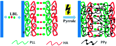
In present study, the thin ECH film was fabricated via introducing the electroconductive polymer into the LbL multilayers by electrochemical approach (Scheme 1). Poly(L-lysine)/sodium hyaluronate (PLL/HA) multilayers is a typical hydrogel film whose thickness increases exponentially with the number of the deposition step, which makes the multilayers to be highly hydrated thin films.16 We chose (PLL/HA) multilayers as matrix hydrogel films. Polypyrrole (PPy), that is a typical electroconductive polymer with very good biocompatibility17 and electrochemical property,18 was incorporated into the (PLL/HA) multilayers by in situ electropolymerization method. Chronopotentiometry and electro-quartz crystal microbalance (E-QCM) were used to follow the electropolymerization of pyrrole. The chemical and structure properties of the (PLL/HA)@PPy films were investigated in detail. Furthermore, the correlation between the electropolymerization time and the electroconductivity of the thin ECH films was evaluated via electrochemical impedance spectroscopy (EIS) and cyclic voltammetry (CV).


image file: c4ra03309d-s1.tif
Scheme 1 Illustration of the buildup of (PLL/HA)16 multilayers and further electropolymerization of pyrrole within the multilayers.

Experimental

Materials

Poly(L-lysine) (PLL, Mw 30[thin space (1/6-em)]000–70[thin space (1/6-em)]000), pyrrole (reagent grade, 98%) and sodium p-toluenesulfonate were purchased from Sigma-Aldrich (USA). Sodium hyaluronate (HA, Mw 200–400 kDa) was purchased from Bloomage Freda (China). Sodium chloride was purchased from Sinopham Chemical Reagent (China). Indium tin oxide (ITO) coated glass (sheet resistance <7 Ω sq−1, transmittance >77%) was purchased from Zhuhai Kaivo Electronic Components (China). Ultrapure water (18 MΩ, Milli-Q Ultrapure Water System, Milli-pore) was used to prepare all solutions. All reagents were used as received except pyrrole which was distilled prior to use.

FITC-labeled PLL (PLL-FITC) was prepared by adding FITC succinimidyl ester (10 mg ml−1 in DMSO) to 1 mg ml−1 PLL aqueous solutions at 4 °C for 24 h. The mixture was dialyzed in ultrapure water for 2 weeks, and then lyophilized.19

Fabrication of (PLL/HA) multilayers

Quartz substrates (10 × 20 mm2), circular glass coverslips (diamater = 14 mm), silicon wafers and Au-coated silicon wafers were cleaned by soaking in a Piranha solution (98% H2SO4[thin space (1/6-em)]:[thin space (1/6-em)]30% H2O2 = 7[thin space (1/6-em)]:[thin space (1/6-em)]3 (v%)) for 5 min, then soaking in the 30% H2O2, 25% NH3 and H2O mixture with the volume ratio of 1[thin space (1/6-em)]:[thin space (1/6-em)]1[thin space (1/6-em)]:[thin space (1/6-em)]5 at 70 °C for 10 min, and finally rinsed thoroughly with water and dried with a stream of nitrogen. ITO glasses were cleaned by a routine cleaning procedure,20 which included initial manual washing in aqueous detergent, and then sequentially sonication in acetone, ethanol, and deionized water for 10 minutes respectively, finally rinsing with ethanol and drying in nitrogen stream.

PLL and HA were dissolved in 0.15 M NaCl aqueous solution at concentration of 0.5 mg ml−1 and 1 mg ml−1 respectively. During the build-up of (PLL/HA) multilayers, all the rinsing steps were performed with 0.15 M NaCl aqueous solution. The (PLL/HA) multilayers with 16 bilayers were constructed using typical LbL deposition technique.21 Briefly, the substrates were firstly immersed in PLL solution for 8 minutes, and rinsed three times with NaCl buffer. The substrates were then immersed in HA solution for 8 minutes, followed by rinsing in NaCl buffer three times. The above procedures were repeated until 16 pairs were constructed.

Electropolymerization of pyrrole

The electropolymerization of pyrrole was carried out on an electrochemical workstation (CHI660D, Chenhua Shanghai, China). The counter electrode was a platinum foil (2 × 2 cm2), and the reference was a saturation calomel electrode (SCE) (KangNing Electro-optic Technology, China). The ITO glasses or Au-coated silicon wafers, which were coated with (PLL/HA) multilayers, acted as working electrodes. Before the electropolymerization, the working electrodes were bathed in pyrrole solution (0.05 M pyrrole in NaCl buffer, with 0.01 M sodium p-toluenesulfonate) for 1 hour. The electrodes were then put in the electrochemical cell filled with pyrrole solution. Pyrrole monomers within the multilayers were polymerized by chronopotentiometry with fixing current at 0.05 mA cm−2 in nitrogen atmosphere. The electropolymeirzation time varied from 0 to 500 s. The resulting films were short for (PLL/HA)16@PPy|n unless otherwise stated (n = electropolymerization time). The pure PPy, which was prepared by electropolymerization of pyrrole on bare ITO glasses or Au-coated silicon wafers was used as control.

Electro-quartz crystal microbalance (E-QCM)

E-QCM is the combination of a commercial quartz crystal microbalance with dissipation (QCM-D, Q-Sense E4 system along with the electrochemistry module (QEM 401), Sweden) and the CHI660D electrochemical workstation. The QCM chamber worked as a three-electrode electrochemical cell with Ag/AgCl reference electrode, platinum counter electrode, and Au coated quartz crystal as the working electrode. The (PLL/HA)16 multilayers were assembled on the crystal. The crystal was put into the electrochemical cell for further reaction. The electropolymerization parameters were the same as described in Electropolymerization of pyrrole.

Characterization of the (PLL/HA)16@PPy films

Optical photographs of the (PLL/HA)16, (PLL/HA)16@PPy, and pure PPy films on ITO glasses were taken by camera (DSC-H50, Sony, Japan). The ultraviolet absorbance spectra of the (PLL/HA)16@PPy films on ITO glasses were obtained using a UV-vis spectrometer (UV-2505, Shimadzu, Japan). Attenuated total reflection Fourier transform infrared spectroscopy (ATR-FTIR) was carried out on Thermo-Fisher scientific LLC ATR-FTIR Nicolet 6700 spectrometer. For ATR-FTIR measurement, the (PLL/HA)16@PPy|500s and the pure PPy films were firstly peeled off from the ITO glasses under concentrated acid condition, which were then transferred to PET sheets, and air-dried at room temperature. The (PLL/HA)16 multilayers was directly assembled on PET sheets. Surface chemical analyses of the (PLL/HA)16, (PLL/HA)16@PPy|500s, and pure PPy films were performed by X-ray photoelectron spectroscopy (XPS, ESCALAB 250Xi, Thermo Scientific). Samples for XPS measurement were fabricated on Au-coated silicon wafers. Confocal laser scanning microscopy (CLSM) investigation was conducted with a Leica SP5X microscope. The (PLL/HA)16 multilayers and (PLL/HA)16@PPy|500s film coated ITO glasses were firstly immersed in PLL-FITC for 8 minutes and then rinsed with NaCl buffer three times. The samples were then put in a CLSM plate (Mattek, diameter = 14 mm) with buffer solution for observation. Transmission electron microscopy (TEM) analysis was performed on a JEM-1230EX at 80 kV in bright field mode. For TEM observation, the (PLL/HA)16@PPy film was firstly peeled off the ITO glass under concentrated acid condition and then transferred to a 400-mesh copper grid and air-drying the grid at room temperature. The surface and cross-section images of the (PLL/HA)16, (PLL/HA)16@PPy|500s and pure PPy films were observed by a field-emitting scanning electron microscope (FESEM) (Hitachi S-4800, Japan) with a voltage of 3.0 kV. The (PLL/HA)16 multilayers were deposited on circular glass coverslips. The (PLL/HA)16@PPy|500s and pure PPy films were constructed on Au-coated silicon wafers.

Electrochemical characterization of the (PLL/HA)16@PPy films

Electrochemical impedance spectroscopy (EIS) and cyclic voltammetry (CV) for the evaluation of the electroconductivity of (PLL/HA)16@PPy|n films were carried out in 0.15 M NaCl aqueous solution. In both measurements, the counter electrode was platinum foil (2 × 2 cm2) and the reference was a SCE. The (PLL/HA)16@PPy|n thin ECH films coated ITO glasses were the working electrode. The initial potential of EIS was set as the open circuit potential, and the frequency range varied from 100 kHz to 10 MHz with amplitude of 10 mV. The cycling voltage chosen was from 0 to 0.6 V to prevent side reactions. The scan rate was 50 mV s−1.

Results and discussion

Due to the simple preparation, good redox property, environmental stability and biocompatibility, PPy has been applied in a wide range of biomedical applications, such as drug delivery system22–24 and electrochemical biosensor.25,26 Electrochemical techniques, such as potentiostatic (cyclic voltammetric),27 galvanostatic (chronopotentiometry)28 and potentiodynamic (chronoamperometry)29 approaches are generally preferred to synthesis PPy. Compared to the chemical oxidation, electrochemical ways could provide a better controlling of the polymerization reaction and tuning of the properties of resulting PPy.30 Among the three electropolymerization approaches, the chronopotentiometry, i.e. measuring the potential as a function of time, can readily control the charge density and fix the kinetics of electrochemical discharge of the monomer.28 It is the most desirable for quantitative research. Thereafter, we selected the chronopotentiometry to polymerize pyrrole.

The (PLL/HA)16 multilayers were firstly deposited on the substrates by LbL technology. PPy was then synthesized within the (PLL/HA)16 multilayers by the galvanostatic method at a fix current 0.05 mA cm−2. The chronopotentiograms of the electropolymerization of pyrrole for (PLL/HA)16@PPy and pure PPy films are shown in Fig. 1. Sodium p-toluenesulfonate was used as counter anion doping to balance the positive charges across the PPy chain and thereby to favor the electropolymerization reaction. As shown in Fig. 1, the following smooth plateau after the initial anodic peak indicates the stable growth of PPy.27 It is worth noting that the electropolymerization process has very good reproducibility. The (PLL/HA)16@PPy|n films with different polymerization time corresponding to 0, 30, 50, 100, 200, 300, 400, and 500 s were prepared. Pure PPy film (electropolymerization of pyrrole for 500 s) serves as control.


image file: c4ra03309d-f1.tif
Fig. 1 The chronopotentiograms of the eletropolymerization of pyrrole with or without the (PLL/HA)16 multilayers.

The electropolymerization of pyrrole within the (PLL/HA)16 multilayer films was also monitored by E-QCM analysis. A linear decrease of the QCM frequency is observed (Fig. 2a), which suggests a linear and smooth mass increase of PPy within the multilayers. More important, the reaction can be precisely controlled by simply turn on/off the electric current (Fig. 2b). QCM was used to calculate the relative mass of the (PLL/HA)16 multilayers and the PPy that electropolymerized into the multilayers. According to the Sauerbrey equation,31 the mass ratio of PPy component is about 50% for the (PLL/HA)16@PPy|500s film. In all, the chronopotentiograms and the E-QCM results suggest that thin (PLL/HA)16@PPy films were successfully fabricated.


image file: c4ra03309d-f2.tif
Fig. 2 (a) The E-QCM measurement of electropolymerization of pyrrole within the (PLL/HA)16 multilayers for 500 s; (b) the control of the electropolymerization showing discontinuous decreasing of frequencies.

Optical photographs give the visualized evidence of the formation of (PLL/HA)16@PPy films. As can be seen in Fig. 3a, the samples become gradually darker with the electropolymerization time, and the electropolymerized PPy could be recognized with naked eyes from ∼100 s. To confirm integrity of the (PLL/HA)16 multilayers after electropolymerization, the cross-section image of the hydrated (PLL/HA)16 multilayers and (PLL/HA)16@PPy|500s films were obtained by CLSM (Fig. 3b). Because the diffusion of PLL-FITC,32 the films can be easily recognized and their thickness could be approximately estimated. It has reported that the thickness of (PLL/HA) multilayers with bilayer number 12–24 could be of the order of 1–4 μm.33 In present study, the thickness of (PLL/HA)16 multilayers is ∼2 μm. As shown in Fig. 3b, thickness of (PLL/HA)16@PPy|500s films is also about 2 μm, which demonstrates the stability of the (PLL/HA)16 multilayers after the electropolymerization process.


image file: c4ra03309d-f3.tif
Fig. 3 (a) The optical images of pure PPy (600 s, the leftmost one) and the (PLL/HA)16 multilayers for different electropolymerization time: 600, 500, 400, 300, 200, 100, 50, 30, and 0 s (from the second left to the rightmost). All samples were prepared on ITO glass. (b) Vertical section images of the (PLL/HA)16 multilayers and the (PLL/HA)16@PPy|500s obtained by CLSM observation.

To further confirm the electropolymerization process, UV-vis analyses of (PLL/HA)16@PPy were performed with the pure (PLL/HA)16 multilayers as baseline (Fig. 4). The absorbance over the scanning range increases correspondingly with the polymerization time. The absorbance peak between 400 and 500 nm results from electric transitions between the valence band and the bipolaron band of PPy.34 The increasing peak intensity over time indicates the continuous growing of PPy within the multilayers. The conjugation length of PPy chain increases and, consequently, the band gap and the energy needed for electron transition decrease, which ultimately lead to the positive shift of the peak absorbance. The widening of the peak maybe because the increased size distribution of PPy particles in the light of quantum size effect. It suggests that the (PLL/HA)16@PPy could be constructed with fine control of the composition. Furthermore, the clear absorbance increase in the near infrared region is the hint of increased conductivity.


image file: c4ra03309d-f4.tif
Fig. 4 UV-visible spectroscopy of the (PLL/HA)16@PPy films with different electropolymerization time: 0, 100, 200, 300, 400, 500 s. The (PLL/HA)16 multilayers (0 s) served as baseline.

ATR-FTIR measurement was employed to probe the chemical signature of the (PLL/HA)16@PPy films. Fig. 5 shows the spectra of (PLL/HA)16 multilayers, (PLL/HA)16@PPy|500s and pure PPy film. The characteristic peaks of carboxylic acid (1715 cm−1), saccharide rings (1245 cm−1), and saccharide peak (1045 cm−1) on the curve of the (PLL/HA)16 multilayers confirm the successful LbL assembly.35 The spectrum of pure PPy film exhibits the main characteristic bands: the pyrrole ring vibration at 1540 and 1446 cm−1, the C–H in-plane deformation at 1300 and 1040 cm−1, and the C–N stretching vibration at 1160 cm−1. The results are in consistent with the literatures.36,37 The appearance of the characteristic peak of the (PLL/HA)16 multilayers and the pyrrole ring vibration peak (1540 cm−1) on the spectrum of the (PLL/HA)16@PPy|500s film demonstrates the successful combination of PPy into the (PLL/HA)16 multilayers.


image file: c4ra03309d-f5.tif
Fig. 5 ATR-FTIR spectra of pure PPy film, the (PLL/HA)16 multilayers, and the (PLL/HA)16@PPy|500s.

XPS measurement is frequently used to obtain atomic information of the element composition of the nearest surface (<100 Å). Since the chemical difference of PPy from PLL and HA, their C/N content ratio are different. XPS wide scan spectra of various surfaces are shown in Fig. 6. The C/N ratio of pure PPy film and the (PLL/HA)16 multilayers are 8.33 and 9.58, respectively. While, the C/N ratio of (PLL/HA)16@PPy|500s film is 8.74, which indicates that (PLL/HA)16@PPy|500s film is a combination of the (PLL/HA) multilayers and PPy.


image file: c4ra03309d-f6.tif
Fig. 6 Wide-scan XPS spectra of pure PPy film, the (PLL/HA)16 multilayers, and the (PLL/HA)16@PPy|500s.

SEM measurement was used to characterize surfaces and cross-section structural features of the dried samples. As shown in Fig. 7a and d, the (PLL/HA)16 multilayers show a smooth and homogenous surface, as previously reported.16 The thickness of the (PLL/HA)16 multilayers is ∼150 nm, which thus indicates a high swelling ratio of (PLL/HA)16 multilayers as considering the thickness (2 μm) estimated from CLSM result (Fig. 3b). The pure PPy film has a very rough surface with lots of granules,38 and its thickness was ∼90 nm (Fig. 7c and f). For the (PLL/HA)16@PPy|500s film (Fig. 7b and e), it shows different surface structure compared with (PLL/HA)16 multilayers and pure PPy film: rougher surface than (PLL/HA)16 multilayers with small while very homogeneous granules, and the thickness is ∼190 nm. No layered structure can be seen in the cross-section image of (PLL/HA)16@PPy film. Such relatively homogeneous surface and cross-section structure might be ascribed to the uniform combination of PPy and the smooth (PLL/HA)16 multilayers. Combining with the XPS data, it could be conceived that PPy had grown from bottom of the multilayers to the outmost surface. TEM was used to observe the distribution of PPy within the (PLL/HA)16@PPy film in higher resolution. As shown in Fig. 8, PPy particles distributes within the (PLL/HA)16@PPy|500s film. SEM and TEM images suggest that PPy was successfully synthesized and incorporated into the (PLL/HA) hydrogel multilayers.


image file: c4ra03309d-f7.tif
Fig. 7 SEM images show the surfaces and cross-section features of the (PLL/HA)16 multilayers (a and d), the (PLL/HA)16@PPy|500s (b and e), and pure PPy film (c and f).

image file: c4ra03309d-f8.tif
Fig. 8 TEM image of (PLL/HA)16@PPy|500s shows that there are lots of small and relative big PPy granules (black ones) well-distributed within the films. Scale bar is 200 nm.

The electrochemical performance of the (PLL/HA)16@PPy films was evaluated using EIS and CV measurements. Nyquist plotting of EIS shows a plot of the imaginary impedance component (Z′′) versus real component (Z′). Diameter of the semi-circles at high frequency range provides the charge transfer resistance information. As shown in Fig. 9a, diameter of the semi-circles decreases as the electropolymerization time increases. The (PLL/HA)16@PPy films with electropolymerization time of 100, 200, 300, and 400 s (corresponding to 5, 10, 15, and 20 mC charge passed), have impedance of 80, 40, 20 and 5 Ω, respectively. It could be concluded that the electroconductivity of the (PLL/HA)16@PPy films would be precisely controlled. The impedance of [poly(HEMA)] Gel-PPy ECH films reported by Guiseppi-Elie et al. is 100 Ω after a charge passing of 25 mC.8 While for the (PLL/HA)16@PPy films, the impedance decreases to 5 Ω after only 20 mC charge passed. This difference in impedance may attribute to the different thickness of films, because the thickness of the Guiseppi-Elie's film is ∼5 μm (measured by SEM), which is much thicker than the (PLL/HA)16@PPy films (only ∼200 nm). The EIS data indicates that the (PLL/HA)16@PPy films have very good and controllable electroconductivity. At low frequency region, the straight line with a slope of about 45 degree was bound up with Warburg resistance owing to the diffusion controlled doping and de-doping of electrolyte ions.39


image file: c4ra03309d-f9.tif
Fig. 9 Nyquist plot (a) and cyclic voltammetry curve (b) of (PLL/HA)16@PPy with different electropolymerization time.

Conclusions can also be drawn from the CV data that concerns charge transfer, charge transport processes, and the interactions that happen among the polymer, the ions, and solvent molecules.40 As can be seen in Fig. 9b, the voltammetric current of the (PLL/HA)16 multilayers is on 10−7 A order of magnitude, whereas the current of (PLL/HA)16@PPy films is 100–1000 times higher. The current positively correlates with the electropolymerization time, which corresponds to an increasing of PPy within the films. Both EIS and CV data suggest that the electroconductivity of the (PLL/HA)16@PPy films can be precisely controlled through changing the electropolymerization time of PPy. As the electropolymerization time going, the conjugation between the (PLL/HA)16 multilayers and PPy tend to be mature, which results in the decrease of band gap and enhancement of electron delocalization.

Conclusions

The thin ECH film was fabricated by in situ electropolymerization of pyrrole within the (PLL/HA)16 multilayers. The hydrogel (PLL/HA)16 multilayers was LbL fabricated with thickness of ∼2 μm. PPy was then successfully incorporated into the multilayers by electropolymerization through galvanostatic technique with fix current of 0.05 mA cm−2. The incorporated PPy endows the films with good electroconductivity. More important, through controlling of electropolymerization time, the impedance of the (PLL/HA)16@PPy films could be easily modulated. Such thin ECH films could serve as surface modification approach and research platform in the field of implantable electro-related biomedical devices and biosensors.

Acknowledgements

Financial support from the National Natural Science Foundation of China (50830106, 21174126, 51103126, 51333005, 21374095), China National Funds for Distinguished Young Scientists (51025312), the National Basic Research Program of China (2011CB606203), Open Project of State Key Laboratory of Supramolecular Structure and Materials (SKLSSM201316), Research Fund for the Doctoral Program of Higher Education of China (20110101110037, 20110101120049 and 20120101130013), and the Qianjiang Excellence Project of Zhejiang Province (2013R10035) is gratefully acknowledged.

Notes and references

  1. H. Ding, M. Zhong, Y. J. Kim, P. Pholpabu, A. Balasubramanian, C. M. Hui, H. He, H. Yang, K. Matyjaszewski and C. J. Bettinger, ACS Nano, 2014, 8, 4348–4357 CrossRef CAS PubMed.
  2. Y. Shi, L. Pan, B. Liu, Y. Wang, Y. Cui, Z. Bao and G. Yu, J. Mater. Chem. A, 2014, 2, 6086–6091 CAS.
  3. P. Chansai and A. Sirivat, Biomedical Applications of Smart Materials, Nanotechnology and Micro/Nano Engineering, 2009, 57, 170–175 Search PubMed.
  4. L. Jin, Y. J. Zhao, X. Liu, Y. L. Wang, B. F. Ye, Z. Y. Xie and Z. Z. Gu, Soft Matter, 2012, 8, 4911–4917 RSC.
  5. M. B. Runge, M. Dadsetan, J. Baltrusaitis, T. Ruesink, L. C. Lu, A. J. Windebank and M. J. Yaszemski, Biomacromolecules, 2010, 11, 2845–2853 CrossRef CAS PubMed.
  6. S. R. Shin, S. M. Jung, M. Zalabany, K. Kim, P. Zorlutuna, S. B. Kim, M. Nikkhah, M. Khabiry, M. Azize, J. Kong, K. T. Wan, T. Palacios, M. R. Dokmeci, H. Bae, X. W. Tang and A. Khademhosseini, ACS Nano, 2013, 7, 2369–2380 CrossRef CAS PubMed.
  7. R. A. Green, R. T. Hassarati, J. A. Goding, S. Baek, N. H. Lovell, P. J. Martens and L. A. Poole-Warren, Macromol. Biosci., 2012, 12, 494–501 CrossRef CAS PubMed.
  8. G. Justin and A. Guiseppi-Elie, Biomacromolecules, 2009, 10, 2539–2549 CrossRef CAS PubMed.
  9. G. Justin, S. Finley, A. R. Abdur Rahman and A. Guiseppi-Elie, Biomed. Microdevices, 2009, 11, 103–115 CrossRef CAS PubMed.
  10. L. Montero, G. Gabriel, A. Guimera, R. Villa, K. K. Gleason and S. Borros, Vacuum, 2012, 86, 2102–2104 CrossRef CAS PubMed.
  11. G. Decher, Science, 1997, 277, 1232–1237 CrossRef CAS.
  12. P. T. Hammond, Mater. Today, 2012, 15, 196–206 CrossRef CAS.
  13. V. Kozlovskaya, E. Kharlampieva, I. Erel and S. A. Sukhishvili, Soft Matter, 2009, 5, 4077–4087 RSC.
  14. X. Zhang, Y. Guan and Y. J. Zhang, Biomacromolecules, 2012, 13, 92–97 CrossRef CAS PubMed.
  15. E. Kharlampieva, I. Erel-Unal and S. A. Sukhishvili, Langmuir, 2007, 23, 175–181 CrossRef CAS PubMed.
  16. C. Picart, P. Lavalle, P. Hubert, F. Cuisinier, G. Decher, P. Schaaf and J. C. Voegel, Langmuir, 2001, 17, 7414–7424 CrossRef CAS.
  17. X. Cui, V. A. Lee, Y. Raphael, J. A. Wiler, J. F. Hetke, D. J. Anderson and D. C. Martin, J. Biomed. Mater. Res., 2001, 56, 261–272 CrossRef CAS.
  18. J. H. Collier, J. P. Camp, T. W. Hudson and C. E. Schmidt, J. Biomed. Mater. Res., 2000, 50, 574–584 CrossRef CAS.
  19. L. Shen, B. Wang, J. Wang, J. Fu, C. Picart and J. Ji, ACS Appl. Mater. Interfaces, 2012, 4, 4476–4483 CAS.
  20. Q. Liu, Y. Liu, L. Ai, Y. Wang, X. Ouyang, L. Han and Z. Ge, New J. Chem., 2013, 170, 57–64 Search PubMed.
  21. K. Ren, T. Crouzier, C. Roy and C. Picart, Adv. Funct. Mater., 2008, 18, 1378–1389 CrossRef CAS PubMed.
  22. K. M. Sivaraman, B. Ozkale, O. Ergeneman, T. Luhmann, G. Fortunato, M. A. Zeeshan, B. J. Nelson and S. Pane, Adv. Healthcare Mater., 2013, 2, 591–598 CrossRef CAS PubMed.
  23. L. L. Miller, B. Zinger and Q. X. Zhou, J. Am. Chem. Soc., 1987, 109, 2267–2272 CrossRef CAS.
  24. D. Svirskis, M. Sharma, Y. Yu and S. Garg, Ther. Delivery, 2013, 4, 307–313 CrossRef CAS PubMed.
  25. R. E. Ionescu, S. Herrmann, S. Cosnier and R. S. Marks, Electrochem. Commun., 2006, 8, 1741–1748 CrossRef CAS PubMed.
  26. S. Mondal and M. V. Sangaranarayanan, Sens. Actuators, B, 2013, 177, 478–486 CrossRef CAS PubMed.
  27. Y. Yuan, S. Adeloju and G. Wallace, Eur. Polym. J., 1999, 35, 1761–1772 CrossRef CAS.
  28. T. M. Higgins, S. E. Moulton, K. J. Gilmore, G. G. Wallace and M. in het Panhuis, Soft Matter, 2011, 7, 4690–4695 RSC.
  29. A. Guiseppi-Elie, Biomaterials, 2010, 31, 2701–2716 CrossRef CAS PubMed.
  30. M. Gandhi, P. Murray, G. Spinks and G. Wallace, Synth. Met., 1995, 73, 247–256 CrossRef CAS.
  31. G. Sauerbrey, Z. Phys., 1959, 155, 206–222 CrossRef CAS.
  32. C. Porcel, P. Lavalle, V. Ball, G. Decher, B. Senger, J.-C. Voegel and P. Schaaf, Langmuir, 2006, 22, 4376–4383 CrossRef CAS PubMed.
  33. T. Boudou, T. Crouzier, K. Ren, G. Blin and C. Picart, Adv. Mater., 2010, 22, 441–467 CrossRef CAS PubMed.
  34. E. S. Lee, J. H. Park, G. G. Wallace and Y. H. Bae, Polym. Int., 2004, 53, 400–405 CrossRef CAS.
  35. L. Shen, P. Chaudouet, J. Ji and C. Picart, Biomacromolecules, 2011, 12, 1322–1331 CrossRef CAS PubMed.
  36. X. Yang, Z. Zhu, T. Dai and Y. Lu, Macromol. Rapid Commun., 2005, 26, 1736–1740 CrossRef CAS.
  37. P. Dallas, D. Niarchos, D. Vrbanic, N. Boukos, S. Pejovnik, C. Trapalis and D. Petridis, Polymer, 2007, 48, 2007–2013 CrossRef CAS PubMed.
  38. M. B. Runge, M. Dadsetan, J. Baltrusaitis, T. Ruesink, L. Lu, A. J. Windebank and M. J. Yaszemski, Biomacromolecules, 2010, 11, 2845–2853 CrossRef CAS PubMed.
  39. L. Liu, J. Yang, Y. Jiang, Y. Huang and Q. Meng, Synth. Met., 2013, 170, 57–62 CrossRef CAS PubMed.
  40. G. Inzelt, Conducting polymers: a new era in electrochemistry, Springer-Verlag, Berlin, Heidelberg, 2008, pp. 67–122 Search PubMed.

This journal is © The Royal Society of Chemistry 2014
Click here to see how this site uses Cookies. View our privacy policy here.