Amorphous nickel–boron and nickel–manganese–boron alloy as electrochemical pseudocapacitor materials
Wei Zhang,
Yueyue Tan,
Yilong Gao,
Jianxiang Wu,
Bohejin Tang* and
Jiachang Zhao
College of Chemistry and Chemical Engineering, Shanghai University of Engineering Science, Shanghai 201620, China. E-mail: tangbohejin@sues.edu.cn
First published on 16th June 2014
Abstract
The nanoparticles of amorphous Ni–B and Ni–Mn–B alloys are synthesized and investigated as electrochemical pseudocapacitor materials for potential energy storage applications. The specific capacitance of Ni–B and Ni–Mn–B electrodes are observed to be 562 and 768 F g−1, respectively. The capacitance of Ni–B and Ni–Mn–B retained 65% and 68% of their initial value after a cycle life of 1500 cycles.
The increasing demand for energy and growing concern about air pollution and global warming have stimulated intense research on energy storage and conversion from alternative energy sources. Supercapacitors, as charge-storage devices exhibit high power density, excellent reversibility and cycleability, and have attracted tremendous attention due to the growing demand for power systems delivering significant energy in the high power region.1 These devices store energy using either ion adsorption (electrochemical double layer capacitors) or fast surface redox reactions (pseudocapacitors).2,3 Electrical double layer capacitor materials are usually carbon materials with high surface area such as carbon nanotubes,4,5 porous carbon,6,7 and graphene,8,9 since the specific capacitance relies on the electrical charge stored at the interface between and the electrode and electrolyte. However, double layer capacitor materials often have low energy storage media due to the low specific capacitance. For this reason, the selection of a suitable electrode material is one of the keys to obtain better performing supercapacitors. So the pseudocapacitors, which rely on faradic reactions, can achieve much higher specific capacitance than electrical double layer capacitors. Among the well known pseudo capacitor materials, RuO is widely studied as a wonderful electrode material with very high specific capacitance,10 but its high cost and low abundance hamper its practical application. Therefore, various metal oxides such as MnO2, NiO, MoO, CoO, vanadium based oxides, etc., are being studied for their electrochemical capacitor properties in different aqueous electrolytes.11–15 The exploration of electrode materials with higher power performance and low cost for pseudo capacitors is still of great importance.
These amorphous alloys are comprised of solid particles with irregular shape and broad size distribution due to particle agglomeration, which have attracted a great deal of attention due to their interesting intrinsic properties, short-range order, long-range disorder and highly unsaturated sites.16 Metal borides represent a typical class of amorphous alloys which have been most thoroughly studied.17,18 They have been widely studied in catalytic reaction owing to their higher activity, and better selectivity.19 However, we rarely discovered this material applied in pseudo capacitors. In the previous report, we find that Kang et al.20 demonstrated a facile approach to fabricate the low-cost nanoporous oxy-hydroxide@NPM hybrid electrode with the high specific capacitance and cyclic stability. Wang et al.21 prepared an ultra-fine amorphous alloy by chemical reduction in aqueous sodium borohydride solution. They reported the exceptional electrochemical activities of amorphous Fe–B and Co–B alloy powders used as high capacity anode materials. Liu et al.22 investigated the structure and electrochemical behaviors of Co–B alloys. They have interpreted the excellent cycling stability of Co–B alloys by the mechanism of discharge process. Through the previous researches, we can clearly find the good electrochemical properties of amorphous alloys, but no one applied it to the pseudo capacitors. In this thesis, we tried to take the characteristics advantages of an amorphous alloy and apply the materials for pseudo capacitors, in order to break through in the special capacitance.
As shown in Fig. 1, the TEM morphology revealed that the Ni–B samples were present in the form of spherical particles with an average diameter of around 5 nm diameter. But after metal element Mn was added, the shape of particle changed to ellipse while also increasing in size to around 25 nm. The amorphous characteristics of the Ni–B and Ni–Mn–B could be further confirmed by selected area electron diffraction (SAED), which displayed various diffractional cycles characteristic of the amorphous structure.
 | ||
| Fig. 1 TEM micrograph of the NI–B (a) and NI–MN–B (b). | ||
ICP analysis demonstrated that all the Ni–B and Ni–Mn–B samples displayed similar atomic compositions (Ni77B23 and Ni64Mn20B16). Ni–B and Ni–Mn–B alloy samples were characterized by X-ray power diffraction (XRD). The synthesized sample shows a broad diffraction peak around 2θ = 45° in the XRD pattern in Fig. 2, indicating the amorphous nature of the sample.23,24 Notably, the patterns contained no distinct peak corresponding to a crystalline phase. Compared with the peaks of Ni–Mn–B, the peak of the Ni–B sample is broader. It implies that the particles of Ni–Mn–B are bigger than the Ni–B, which accords with the observe result of TEM micrograph.
 | ||
| Fig. 2 XRD patterns of the NI–B and NI–MN–B. | ||
Fig. 3 shows the effect of various scan rates on CV response of the Ni–B and NI–MN–B in 6 mol L−1 KOH electrolyte at the scan rates of 5, 10, 20, 30, 40 and 50 mV s−1. The Cyclic voltammograms of the different composite electrodes with a potential window from −0.2 to 0.8 V are shown in Fig. 3.
 | ||
| Fig. 3 The cyclic voltammetry curves of NI–B (3.675 mg) and NI–MN–B (4.80 mg). | ||
The cyclic voltammetry (CV) curves have two typical redox peaks, indicating it is pseudocapacitance. All the CV curves of Ni–Mn–B are almost symmetric, and the peak current increases with increasing scan rate, with a little shift in both cathodic and anodic peak potentials with respect to scan rate, suggesting their good reversibility of fast charge–discharge response.25,26 The CV curves of NI–B is symmetric at a low scan rate, however, the symmetry weakens with the increasing scan rate. So it is conducive to increase the charge–discharge reversibility of electrode material with adding the Mn element.
From the CV, the specific capacitance can be estimated as follows:27

![[thin space (1/6-em)]](https://www.rsc.org/images/entities/char_2009.gif) dV represents the area under CV curve (Q). All specific capacitance data with various scan rates are collected in Fig. 4.
dV represents the area under CV curve (Q). All specific capacitance data with various scan rates are collected in Fig. 4.
 | ||
| Fig. 4 The specific capacitance of NI–B and NI–MN–B at different scan rates. | ||
The Ni–Mn–B electrodes not only exhibits high specific capacitances but also significantly larger than that of the Ni–B electrode at all scan rates. The electrode material of Ni–Mn–B exhibits a specific capacitance of 768 F g−1 at the scan rate of 5 mV s−1, while the specific capacitance of Ni–Mn–B is about 562 F g−1. Generally, the rate capability is heavily dependent on three processes:28,29 the ion diffusion in the electrolyte, the surface adsorption of ions on the electrode materials and the charge transfer in the electrode. At a high scan rate, any of three processes is relatively slow, which will limit the rate, lowering the specific capacitance. The capacitance of Ni–Mn–B remained 245 F g−1 with a 10-fold increase in scan-rate (from 5 to 50 mV s−1).
Based on the previous reports,21,22 the reactions of the Ni–Mn–B and Ni–B electrodes seem to proceed through the following mechanism:
| NiBx + (6x + 2)OH− → Ni(OH)2 + xBO33− + 3xH2O | (1) |
| MnBx + (6x + 2)OH− → Mn(OH)2 + xBO33− + 3xH2O | (2) |
The exceptionally high capacities of the boride alloys were found due to the electrochemical activation of boron atoms in the highly dispersed transition metal atoms. Inversely, the activated boron clamps the electrode potential to a negative region to prevent the transition metal from passivating.21 Surely such a good capability is attributed to the advantages of the Mn element added. Small sized materials particles resulted in high specific pseudocapacitance.
The galvanostatic charge–discharge tests were further performed in the voltage range of −0.2–0.5 V to estimate the capacitance of the two array electrodes, respectively. Fig. 6 shows the discharge capacitance of the Ni–Mn–B and Ni–B at a current of 5 mA. Evidently, the Ni–Mn–B electrode delivers a much higher specific capacitance than the Ni–B. As shown in the Fig. 5, during charge and discharge, the curves of Ni–Mn–B and Ni–B obviously displayed a slop variation of the time dependence on potential, indicating a typical pseudo-capacitance behavior, which may result from the electrochemical redox reaction at the interface between electrode and electrolyte.
 | ||
| Fig. 5 The galvanostatic charge–discharge curve of Ni–Mn–B (6.525 mg) and Ni –B (6.6 mg) at current of 5 mA. | ||
 | ||
| Fig. 6 Impedance spectrum of Ni–Mn–B and Ni–B (frequency range from 100 kHz to 0.01 Hz). Z′ is real impedance. −Z′' is imaginary impedance. | ||
The specific capacitance can be calculated from the galvanostatic charge–discharge curve according to equation:30

Electrochemical impedance spectra of Ni–Mn–B and Ni–B were measured and Fig. 6 shows the corresponding Nyquist plots. When the plot is shown in a different scale, without the lowest frequencies, a semicircle at the highest frequencies may be seen. The two plots are all composed of a semicircle and a straight line. The semicircle at the higher frequency region should be attributed to the charge transfer process at electrode/electrolyte interface, and the straight line at the lower frequency region should be ascribed to the diffusion process in the solid. The semicircles intercepting the real axis are a combination of solution resistance of electrolyte Rs and charge transfer resistance Rct obtained from the Nyquist plot. The magnitude of Rs of 0.4 and 1.75 ohm were obtained from the x-intercept of the impedance spectra in Fig. 6. The Ni–Mn–B capacitor has the lower resistance due to the highly conductive nature of the Ni–Mn–B material. It also can be seen from Fig. 6 that the semicircle for Ni–Mn–B is a little smaller than that for Ni–B. This indicates that the electrochemical reaction resistance for Ni–Mn–B electrode is smaller. In addition, the straight line at lower frequency region for Ni–Mn–B is more inclined than that for Ni– B, suggesting that the former has a lower electrolyte diffusion resistance than the latter. Thus the amorphous Ni–Mn–B alloy electrode has excellent capacitive behavior.
Fig. 7 describes the cyclic test of Ni–Mn–B and Ni–B electrodes between the potential range of −0.2 to 0.8 V at a scan rate of 10 mV s−1 for 1500 cycles. As the number of cycle increases, the specific capacitance of the electrode material begins to decline. Although the specific capacitance of Ni–Mn–B and Ni–B increased again with cycle increasing, but they eventually decay down to 68% and 65% of their initial value after 1500 cycles, indicating amorphous alloy as well as long term electrochemical and mechanical cycling stabilities.
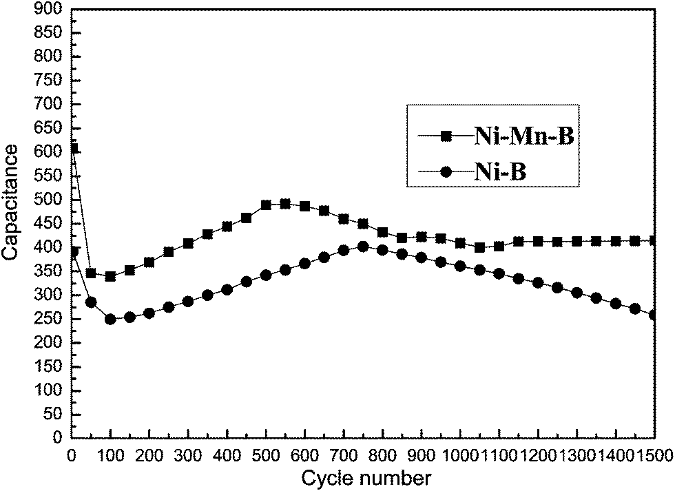 | ||
| Fig. 7 The cycle test of Ni–Mn–B and Ni–B electrodes at a scan rate of 10 mV s−1. | ||
Conclusions
The nanoparticles of amorphous Ni–B and Ni–Mn–B alloy were synthesized and show excellent specific capacitance as electrochemical pseudocapacitor materials. The specific capacitance of Ni –B and Ni–Mn–B electrodes were observed to be 562 and 768 F g−1 at the scan rate of 5 mV s−1 in the electrolyte of 6 M KOH, respectively. Amorphous alloy is a kind of pseudo capacitance materials according to its cyclic voltammetry graph and galvanostatic charge discharge graph. After 1500 cycles, the specific capacitance of Ni–Mn–B and Ni–B electrode materials remain 68% and 65%, showing the good stability. After adding the manganese metal elements, the electrochemical properties of the material were greatly improved. It can get better specific capacitance and smaller resistance than the Ni–B. Surely, the exceptional high capacities of the boride alloys were found due to the electrochemical activation of boron atoms in the highly dispersed transition metal atoms. The amorphous alloy can be considered as a promising electrode material for high performance supercapacitors.Experimental section
Materials
The chemical reduction of the nickel and manganese metallic ions with borohydride (BH4−) is a conventional method of amorphous alloy preparation. The reduction procedure is as follows:| BH4− + 2H2O → BO2− + 4H2 | (3) |
| 2Ni2+ + BH4− + 2H2O → 2Ni + BO2− + 4H+ + 2H2 | (4) |
| BH4− + H2O → B + OH− + 2.5H2 | (5) |
The experimental procedure is as follows: 250 mL of sodium borohydride solution (0.5 mol L−1) was first prepared and adjusted to pH 12 with sodium hydroxide to prevent violent hydrolysis. Bivalent nickel nitrate solution (0.1 mol L, 250 mL) was prepared with degassed distilled water and then cooled in cryostat tank. The chemical reduction reaction was carried out by adding borohydride solution dropwise into Ni(NO3)2·6H2O solution while being stirred. When the addition was complete, the solution bath was continually stirred for about 1 h to release the hydrogen and to prevent burning of the precipitate following filtration and all the reaction was performed under N2 atmosphere. After that, the precipitate was washed first with distilled water to remove the reaction residues, and then with ethanol to prevent the sample surface from further oxidizing. Finally, the sample was dried in a vacuum at 90 °C for 12 h to further remove any residual water or acetone.
The Mn-doped Ni–B amorphous alloy (denoted as Ni–Mn–B) was prepared in a similar way, except a MnCl2·4H2O (molar ratio Mn–Ni = 1:1) was added to the aqueous nickel chloride. All the reagents were of analytical grade and used as received without further purification (Shanghai Chemical Reagent Company).
Characterization
Electrodes for electrochemical performance were constructed by mixing Ni–B (Ni–Mn–B) material, carbon black and poly tetrafluoroethylene (PTFE) binder with the weight percent ratio of 75:20:5, then it was dispersed in alcohol and the mixtures was pressed onto nickel foams at a pressure of 12 MPa. The geometric surface area of the prepared working electrode is 1 cm2, and then the electrodes dried in a vacuum at 90 °C for 1 h to remove the solvent. Nickel foam (1.6 mm thick, 95% purity, Goodfellow) was used as a current collector.
Electrochemical properties and capacitance measurements were performed by the three-electrode configuration. In the three electrode configurations, the Pt grid was adopted as the counter electrode and the prepared electrode was used as the working electrode with a silvewire31 as the reference electrode in 6 M KOH. Cyclic voltammograms, constant current charge–discharge and impedance were performed on a CHI660C instrument in the potential range of −0.2–0.8 V with varied scan rates from 5 to 50 mV s−1. All the experiments were done three times to ensure accuracy.
The powder X-ray diffractions (PXRD) of the samples were performed on a diffraction meter (D/Max-rB) with Cu-Kα radiation (λ = 1.54056 Å) and a graphite monochromator at 50 kV, 100 mA. The chemical composition of NI–B and NI–MN–B alloy powders were analyzed by inductively coupled plasma (ICP, Prodigy, Leeman). The size and morphological view of the alloy powders were observed by a transmission electron microscope (TEM) on Hitachi H-800 microscope.
Acknowledgements
This work was supported by the Fund of Graduate Innovation Project, College of Chemistry and Chemical Engineering, Shanghai University of Engineering Science (A-0903-13-01078).References
- J. Miller, B. Dunn, T. Tran and R. Pekala, J. Electrochem. Soc., 1997, 144, L309–L311 CrossRef CAS PubMed
.
- A. S. Aricò, P. Bruce, B. Scrosati, J.-M. Tarascon and W. Van Schalkwijk, Nat. Mater., 2005, 4, 366–377 CrossRef PubMed
- M. Aizawa, Anal. Chim. Acta, 1991, 250, 249–256 CrossRef CAS
- D. N. Futaba, K. Hata, T. Yamada, T. Hiraoka, Y. Hayamizu, Y. Kakudate, O. Tanaike, H. Hatori, M. Yumura and S. Iijima, Nat. Mater., 2006, 5, 987–994 CrossRef CAS PubMed
- E. Frackowiak, K. Metenier, V. Bertagna and F. Beguin, Appl. Phys. Lett., 2000, 77, 2421–2423 CrossRef CAS PubMed
- W.-C. Chen, T.-C. Wen and H. Teng, Electrochim. Acta, 2003, 48, 641–649 CrossRef CAS
- C. Vix-Guterl, S. Saadallah, K. Jurewicz, E. Frackowiak, M. Reda, J. Parmentier, J. Patarin and F. Beguin, Mater. Sci. Eng., B, 2004, 108, 148–155 CrossRef PubMed
- C. Liu, Z. Yu, D. Neff, A. Zhamu and B. Z. Jang, Nano Lett., 2010, 10, 4863–4868 CrossRef CAS PubMed
- Y. Zhu, S. Murali, M. D. Stoller, K. Ganesh, W. Cai, P. J. Ferreira, A. Pirkle, R. M. Wallace, K. A. Cychosz and M. Thommes, Science, 2011, 332, 1537–1541 CrossRef CAS PubMed
- J. Zheng and Y. Xin, J. Power Sources, 2002, 110, 86–90 CrossRef CAS
- J. Zheng, P. Cygan and T. Jow, J. Electrochem. Soc., 1995, 142, 2699–2703 CrossRef CAS PubMed
- K. C. Liu and M. A. Anderson, J. Electrochem. Soc., 1996, 143, 124–130 CrossRef CAS PubMed
- Y. Yoon, W. Cho, J. Lim and D. Choi, J. Power Sources, 2001, 101, 126–129 CrossRef CAS
- B. Conway, V. Birss and J. Wojtowicz, J. Power Sources, 1997, 66, 1–14 CrossRef CAS
- C. Lin, J. A. Ritter and B. N. Popov, J. Electrochem. Soc., 1998, 145, 4097–4103 CrossRef CAS PubMed
- R. Schwarz and W. Johnson, Phys. Rev. Lett., 1983, 51, 415 CrossRef CAS
- H. Li, H. Li, W.-L. Dai, W. Wang, Z. Fang and J.-F. Deng, Appl. Surf. Sci., 1999, 152, 25–34 CrossRef CAS
- H. Li, H. Li, W. Dai and M. Qiao, Appl. Catal., A, 2003, 238, 119–130 CrossRef CAS
- J.-F. Deng, H. Li and W. Wang, Catal. Today, 1999, 51, 113–125 CrossRef CAS
- J. Kang, A. Hirata, H. J. Qiu, L. Chen, X. Ge, T. Fujita and M. Chen, Adv. Mater., 2014, 26, 269–272 CrossRef CAS PubMed
- Y. Wang, X. Ai, Y. Cao and H. Yang, Electrochem. Commun., 2004, 6, 780–784 CrossRef CAS PubMed
- Y. Liu, Y. Wang, L. Xiao, D. Song, Y. Wang, L. Jiao and H. Yuan, Electrochim. Acta, 2008, 53, 2265–2271 CrossRef CAS PubMed
- J. Guo, Y. Hou, C. Yang, Y. Wang, H. He and W. Li, Catal. Commun., 2011, 16, 86–89 CrossRef CAS PubMed
- G. Bai, L. Niu, M. Qiu, F. He, X. Fan, H. Dou and X. Zhang, Catal. Commun., 2010, 12, 212–216 CrossRef CAS PubMed
- H. KuanXin, Z. Xiaogang and L. Juan, Electrochim. Acta, 2006, 51, 1289–1292 CrossRef PubMed
- J.-H. Zhong, A.-L. Wang, G.-R. Li, J.-W. Wang, Y.-N. Ou and Y.-X. Tong, J. Mater. Chem., 2012, 22, 5656–5665 RSC
- V. Nithya, R. Kalai Selvan, D. Kalpana, L. Vasylechko and C. Sanjeeviraja, Electrochim. Acta, 2013, 109, 720–731 CrossRef CAS PubMed
- J. Li, W. Zhao, F. Huang, A. Manivannan and N. Wu, Nanoscale, 2011, 3, 5103–5109 RSC
- Y. Zhang, G.-y. Li, Y. Lv, L.-z. Wang, A.-q. Zhang, Y.-h. Song and B.-l. Huang, Int. J. Hydrogen Energy, 2011, 36, 11760–11766 CrossRef CAS PubMed
- B. Hu, X. Qin, A. M. Asiri, K. A. Alamry, A. O. Al-Youbi and X. Sun, Electrochim. Acta, 2013, 107, 339–342 CrossRef CAS PubMed
- R. Díaz, M. G. Orcajo, J. A. Botas, G. Calleja and J. Palma, Mater. Lett., 2012, 68, 126–128 CrossRef PubMed
| This journal is © The Royal Society of Chemistry 2014 |