Carbon nanofibers containing Si nanoparticles and graphene-covered Ni for high performance anodes in Li ion batteries

Zheng-Long Xu, Biao Zhang, Zi-Qi Zhou, Sara Abouali, Mohammad Akbari Garakani, Jiaqiang Huang, Jian-Qiu Huang and Jang-Kyo Kim*
Department of Mechanical and Aerospace Engineering, The Hong Kong University of Science and Technology, Clear Water Bay, Kowloon, Hong Kong. E-mail: mejkkim@ust.hk; Fax: +852-2358-1543; Tel: +852-2358-7207

Received 6th April 2014 , Accepted 9th May 2014

First published on 9th May 2014


Abstract

Freestanding, porous carbon nanofiber (CNF) composites containing Si nanoparticles and graphene-covered Ni particles are synthesized via one-pot electrospinning and thermal treatment. The electrodes made from the Si/Ni/CNF composites deliver a remarkable specific capacity of 1045 mA h g−1 at the 50th cycle at a current density of 100 mA g−1 and an excellent high rate capacity of 600 mA h g−1 at 1 A g−1 after 70 cycles with capacity retention of 81%. These values are among the best for similar electrospun Si-based CNF composite electrodes. Two major ameliorating mechanisms are responsible for the finding. The Si particles are fully encapsulated by the soft CNF matrix which serves as the stress buffer to relieve the volumetric stresses stemming from the intercalation/extraction of Li ions into Si and prevent re-agglomeration of Si particles during charge/discharge cycles. The amorphous carbon and the Ni particles surrounded by the crystallized graphene layers effectively form continuous conductive networks which in turn offer fast ion and electron transport paths, giving rise to high rate performance of the electrodes.

Introduction

Li ion batteries (LIBs) have been considered the most promising energy storage system due to their high power density, long life, low cost and environmental friendliness.1 To satisfy the requirements of demanding applications like electric vehicles and portable electronics, anode materials possessing higher capacities, better rate performance and excellent cyclic stability with lower manufacturing costs should be developed.2 Si has attracted much attention due to its highest ever-known theoretical capacity of about 4200 mA h g−1, a low discharge potential of ∼370 mV leading to a long discharge plateau, non-toxic and abundant supply, all of which are suitable for high power LIB anodes.3,4 However, large-scale applications of Si-based electrodes are hampered by their poor rate performance and unsatisfactory cyclic stability. Si suffers from huge volumetric expansion of about 300% during the Li ion insertion process, causing electrode pulverization and loss of electronic contact.5 Among many strategies devised to mitigate these challenges, the encapsulation Si particles within an inactive matrix, like carbon,6–8 is considered one of the most effective and facile approaches that show remarkable improvements in electrochemical performance of the electrodes. This strategy has many advantages, including (i) superior electronic contact between Si particles and carbon matrix, (ii) effective stress buffering action by the soft carbon, and (iii) carbon matrix acting as a barrier to hinder Si re-aggregation during the charge/discharge cycles.

Along with recent studies in the synthesis of high performance metal oxide/carbon nanofiber (CNF) composite electrodes,9,10 Si nanoparticles embedded in electrospun CNFs have been widely explored.11–19 Various structures, like Si/CNF,11–14 Si/porous CNF,15,16 Si core/CNF shell structure,17–19 have been synthesized with varied successes in improving the cyclic performance and rate capacities. Nevertheless, the CNF electrodes made from thermally-treated polymer precursors, such as polyacrylonitrile (PAN) and polyvinyl alcohol (PVA), displayed relatively low electronic conductivities that limited the rate performance.20 To overcome this problem, nanocarbon additives with high conductivities, like graphene21,22 and carbon nanotubes (CNTs),13,23 have been introduced into the electrospun CNF composites. Transition metals, like Ni, Co and Fe, have also been considered as the catalysts to assist graphitization of polymer during calcination.24,25 Further, Ni nanoparticles were successfully incorporated into electrospun CNFs to form uniformly disperse graphene or CNTs for enhanced electrical conductivities,26,27 whereas heavy metals, like Au,28 Ag29,30 and Ni,31 were used to address the inadequate conductivities of Si-based electrodes.

Another critical issue that greatly influences the electrochemical performance of Si-based electrodes is the stability of solid electrolyte interphase (SEI) films that forms as the reaction product on the surface of Si during the charging process.32 Typically, the SEI layers are unstable due to the repetitive expansion and contraction of Si particles during the charge/discharge cycles, leading to cracking of SEI layers to expose fresh Si surface to the liquid electrolyte. Such detrimental cycles cause continuous electrolyte consumption, loss of electronic contact and Si pulverization, resulting in shortened cyclic life of the electrodes. Several new structures have been devised to resolve the issue, such as CNF sheath,17 rigid SiOx shell,32,33 creation of empty space around the Si particles34 and carbon sphere coating,35,36 so as to encapsulate the Si particles to avoid direct contact with the electrolyte as well as to accommodate the large volumetric change of Si.

Herein, we developed novel freestanding Si/Ni/CNF electrodes containing ultrafine Ni conductive particles via a simple, one-pot single-nozzle electrospinning process. Multi-layer graphene was in situ formed surrounding the uniformly dispersed Ni particles within the porous CNFs, which in turn facilitated the fast transfer of Li ions and electrons as well as effectively hindered re-aggregation of Si nanoparticles during lithiation/delithiation. The encapsulation of the active Si particles maintained the stability of SEI layers, which contributed to the excellent cyclic performance of the Si/Ni/CNF composite electrodes.

Experimental

Synthesis of Si/Ni/CNF composites via electrospinning

The agglomerated Si nanoparticles (supplied by Shanghai ST-Nano Sci. & Technol. Co.) were treated with Piranha solution to form hydrophilic surface for dispersion and chemical compatibility of Si with the polymer precursor.14 2.5 g Si particles were magnetically stirred in Piranha solution (H2SO4[thin space (1/6-em)]:[thin space (1/6-em)]H2O2 = 7[thin space (1/6-em)]:[thin space (1/6-em)]3 v/v) at 80 °C for 2 h. The mixture was washed by centrifugation in deionized (DI) water and diluted into 20 mg mL−1 aqueous solution. 0.7 g PVA (Mw = 85[thin space (1/6-em)]000–124[thin space (1/6-em)]000, supplied by Aldrich) was mixed with 10 mL DI water and stirred in a water bath at 90 °C for 8 h to form a homogenous solution. 140 mg treated Si particles were added into the solution and stirred to allow reaction between the treated Si particles and the hydroxyl groups in PVA, followed by addition of 70 mg Ni(Ac)2·4H2O (Mw = 248.84, supplied by Aldrich) and stirring for another 8 h. The as-prepared precursor solution was transferred into a 20 mL syringe with a 19 G needle with an inner diameter 1.1 mm. A high voltage of 27 kV was applied between the needle and rotation collector placed at a constant distance of 18 cm at a flow rate of 1.0 mL h−1. The electrospun composite film was peeled off, followed by stabilization in air at 200 °C for 1 h and carbonization in nitrogen atmosphere at 650 °C for 1 h at a heating rate of 2 °C min−1. The freestanding film synthesized thereby was designated as Si/Ni/CNF, which was directly employed as electrodes without any additives. The control Si/CNF composite films were also prepared using the same procedure without adding Ni(Ac)2·4H2O. For a comparative study, Ni particles were etched off from the Si/Ni/CNF composite by immersing in about 3 mol L−1 HNO3 solution at 90 °C for 8 h to form Si/CNF composites containing graphene pores (designated as Si/CNF/Ni-etch).

Characterization and electrochemical tests

The morphologies of as-prepared composites were examined under a scanning electron microscope (SEM, JEOL-6700F) and a field emission transmission electron microscope (FETEM, JEOL 2010F). The crystalline phases and elemental distributions of the nanofibers were evaluated using the selected-area electron diffraction (SAED) and energy dispersive X-ray spectrometer (EDS) techniques in FETEM. A powder X-ray diffraction (XRD) system (Philips, PW1830) was employed to study the phase structures for 2θ from 10 to 90° at a scanning rate 2° min−1. The surface chemical compositions were studied on an X-ray photoelectron spectroscope (XPS, Surface analysis PHI5600, Physical Electronics). The sheet resistance of the composites was measured using the four-point probe method (Scientific Equipment & Services). The component compositions were evaluated by thermogravimetry analysis (TGA) at a heating rate of 10 °C min−1 in air. Nitrogen absorption–desorption isotherms were obtained on a Micromeritics ASAP 2020 analyzer at 77 K and the corresponding surface areas were determined using the Brunauer–Emmett–Teller (BET) method.

A two-electrode 2032 type coin cell was utilized to assess the electrochemical performance of the electrodes prepared from composite films, similar to our previous studies.14,37 The electrospun composite films were directly used as electrodes without any binder or conductive additives. The films were cut into 10 mm × 10 mm squares as the anodes; Li foils were used as the counter electrodes, 1 M LiPF6 in a solution of ethyl carbonate (EC)–dimethyl carbonate (DMC) mixture (1[thin space (1/6-em)]:[thin space (1/6-em)]1 v/v) as the electrolyte and microporous polyethylene films (Celgard 2400) as the separators. The coin cells were assembled in an argon gas filled glove box. The electrochemical tests were conducted on a LAND 2001 CT system at different current densities between 100 and 1000 mA g−1 and at different potentials between 0 and 3.0 V. The cyclic voltammetry (CV) test was performed on a CHI600c electrochemical workstation at a scan rate 0.1 mV s−1 between 0 and 3.0 V. The electrochemical impedance spectroscopy (EIS) curves were determined at a constant perturbation amplitude 5 mV in the frequency range between 100 kHz and 10 mHz.

Results and discussion

Structures and chemistry of electrode materials

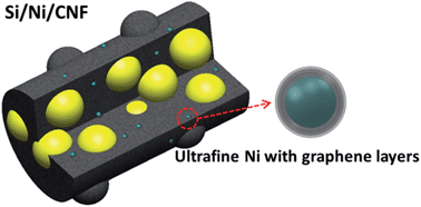
Fig. 1 schematically illustrates the Si/Ni/CNF composite containing well-dispersed, ultrafine Ni particles with surrounding graphene layers. The Ni particles were produced by decomposition of nickel acetate and functioned as catalyst for low temperature graphitization of the PVA to form graphene layers.26,27,38,39 The active Si nanoparticles are fully encapsulated within the amorphous CNFs that not only served as the conducting medium for electron and ion transport, but also as the buffer to relieve the stress arising from the Si expansion and to hinder the re-aggregation of Si particles during the charge/discharge cycles. The SEM images of as-spun fibers shown in Fig. S1 indicate that both the neat PVA fibers and those containing a small amount of Ni precursor, i.e. Ni/PVA fibers, were smooth and had uniform diameters ranging between 80 and 200 nm. Addition of 20 wt% Si particles, Si/Ni/PVA maintained a typical uniform fibrous structure decorated with well-dispersed nanoparticles and limited clusters.
image file: c4ra03066d-f1.tif
Fig. 1 Schematic illustration of Si/Ni/CNF composite.

Typical TEM images taken after thermal treatment are shown in Fig. 2 and S2. Both the crystalline Si particles and ultrafine Ni particles of diameter 2–4 nm were uniformly dispersed within the carbon fiber matrix (Fig. 2a, c and e). The concentration of electrochemically inert Ni particles (∼5.17 wt%) obtained from the EDS analysis (see Fig. S2) was too low to make any significant contribution to the specific capacity of the composite electrodes. It is worth noting that there were a SiO2 layer of thickness ∼3 nm and an amorphous carbon coating of a similar thickness on the Si particle surface (Fig. 2e), both of which are crucial to protecting the Si particles during the lithiation/delithiation processes.33,34 It is postulated that the thin SiO2 layer, as signified by the elemental mapping (Fig. S2) and the XPS analysis (Fig. 4c), was formed as a result of partial oxidation of Si during the thermal treatment. It is noted previously that such a SiO2 layer could interact with Li ions to form a stable Li2Si2O5 phase which was beneficial to cyclic performance of Si anodes.33 The amorphous carbon layer also served as a buffer to relieve the volumetric stresses while providing electron transport paths.35,36 The selected area electron diffraction (SAED) pattern (Fig. 2b) showed obvious spots and ring-like modes, verifying crystalline Si and Ni. The ultrafine Ni particles were surrounded by a few layers of graphene structure with an inter-planer d-spacing of ∼0.34 nm corresponding to (002) plane of carbon (Fig. 2d and f). These graphene layers were shown to contribute not only to improving the electrical conductivity of amorphous CNFs, but also to increasing Li-ion storage sites by creating micropores.25,26 After the removal of Ni particles via acid etching, some Si particles in the Si/CNF/Ni-etch composites were exposed through the locally damaged CNF matrix (Fig. S4) which was caused by the oxidation of amorphous carbon by the acid.40 The direct contact between the exposed Si particles and the electrolyte would be deleterious because the volumetric stresses arising from Si expansion may not be properly relieved, leading to rapid decay of cyclic performance.


image file: c4ra03066d-f2.tif
Fig. 2 (a and c) TEM and (d–f) HRTEM images of Si/Ni/CNF composites; (b) SAED patterns of (a).

image file: c4ra03066d-f3.tif
Fig. 3 (a) XRD patterns, (b) Raman spectra and (c) TGA analysis curves of Si/CNF, Si/Ni/CNF and Si/CNF/Ni-etch composites.

image file: c4ra03066d-f4.tif
Fig. 4 (a) XPS general spectra; deconvoluted high resolution XPS spectra (b) C 1s, (c) Si 2p and (d) Ni 2p of Si/Ni/CNF composite, respectively.

The crystalline structures were studied using the XRD analysis as shown in Fig. 3a. The sharp diffraction patterns of Si/CNF centered at 28.5, 47.4, 56.3, 69.2, 76.4 and 88.0° were consistent with the standard XRD data for Si (PDF number: 27-1402). The broad centered at 24° corresponds to the calcinated carbon.27 The Si/Ni/CNF composites displayed new peaks at 44.4 and 51.9°, corresponding to (111) and (200) crystal planes of Ni (PDF number: 04-0850).41 These Ni peaks disappeared in the Si/CNF/Ni-etch composite after Ni etching, which agreed well with the TEM (Fig. S4) and the XPS and TGA results (Table 1). The Raman spectra (Fig. 3b) showed prominent D- and G-band peaks at about 1350 cm−1 and 1580 cm−1 in all composite samples corresponding to defects or disorder and graphitic carbon, respectively. The ID/IG ratio, a measurement of the amount of disordered carbon, decreased by a large margin from 1.12 to 0.56 after the incorporation of ultrafine Ni particles (see Table 2), a reflection of a higher degree of graphitization due to the catalytic effect of Ni. After the etching of Ni, the ID/IG ratio surged to 1.45 as a result of introduction of defects by the etching process (Fig. S4). The TGA curves shown in Fig. 3c indicate that the Si/CNF and Si/CNF/Ni-etch presented similar curves with a sudden drop in weight at ∼420 °C and a gradual weight regain at above 600 °C, as results of the oxidization of carbon and Si, respectively. The drop and regain of weight were rather gradual, and the temperature corresponding to weight drop up-shifted to ∼440 °C in the case of Si/Ni/CNF, indicating a higher degree of graphitization. At about 600 °C in TGA curve of Si/Ni/CNF, the residual composites were assumed to contain Si and NiO with almost the same Si weight as in Si/CNF/Ni-etch.21,41 Based on the ratio of precursors as well as the TGA curves, a summary of the compositions of the composites is given in Table 1.

Table 1 XPS atomic compositions and TGA components
Samples XPS compositions/at.% TGA components/wt%
C Si O Ni C Si Ni
Si/Ni/PVA 68.3 0.4 30.4 0.2
Si/CNF 68.8 1.1 22.6 0.0 58.1 41.9
Si/Ni/CNF 82.5 2.1 10.3 0.6 ∼47.8 ∼45.1 ∼7.1
Si/CNF/Ni-etch 81.4 2.7 15.9 0.0 54.9 45.1


Table 2 Surface areas, pore volumes, Raman band intensity ratios (ID/IG), electric conductivities and initial Coulombic efficiencies (CE) of composite electrodes
Samples Surface area/m2 g−1 Pore volume/cm3 g−1 ID/IG Conductivity/S cm−1 CE/%
Si/CNF 110.9 0.097 1.12 1.84 × 10⁻⁵ 71.1
Si/Ni/CNF 209.1 0.228 0.56 2.31 × 10⁻³ 82.1
Si/CNF/Ni-etch 170.2 0.226 1.45 9.5 × 10⁻⁵ 67.7


The XPS spectra and the corresponding atomic compositions are shown in Fig. 4 and Table 1. The oxygen contents drastically decreased from 30.4 to 10.3 at.% after thermal treatment, confirming successful carbonization of PVA. The oxygen content in Si/Ni/CNF was much lower than that in Si/CNF, i.e. 10.3 vs. 22.6 at.%, as a result of the catalytic effect of Ni. It worth noting that Si contents in all samples (i.e. 1.1, 2.1 and 2.7 at.% for Si/CNF, Si/Ni/CNF and Si/CNF/Ni-etch, respectively) obtained from the XPS analysis were much lower than the corresponding values taken from the TGA results (i.e. 41.9, ∼45.1 and 45.1 wt%). This observation is attributed to the amorphous carbon coating that inevitably interrupted correct measurements by the XPS analysis. As expected, the Ni2p peak appeared only in the Si/Ni/CNF composite, which disappeared completely in Si/CNF/Ni-etch after etching (Fig. 4a). The C1s peaks (Fig. 4b) were deconvoluted into C–C (284.4 eV), C–O (285.3 eV), C[double bond, length as m-dash]O (287.6 eV) and O–C[double bond, length as m-dash]O (289.6 eV) where the first dominant peak corresponds to the disordered carbon while the last three weak peaks are attributed to the residual groups of thermally treated PVA, indicating successful carbonization of the polymer precursor. The Si2p peaks (Fig. 4c) arose from SiO2 as a result of oxidization of Si nanoparticles, which is consistent with the TEM observation (Fig. 2e). The Ni2p peaks (Fig. 4d) were curve fitted into 852.6 eV for Ni2p3/2 indicating the existence of Ni0.42 The Ni0 state is a reflection of metallic Ni decomposed from the Ni precursor, as suggested by the TEM and XRD results (Fig. 2e and 3a).

The nitrogen absorption–desorption isotherms and BET specific surface areas of the composites are shown in Fig. 5 and the results are summarized in Table 2. All samples presented pronounced hysteresis, indicating the existence of type IV mesopores. According to the Barrett–Joyner–Halenda (BJH) equation, all three materials contained meso (2–50 nm) pores,43 in particular in the Si/Ni/CNF and Si/CNF/Ni-etch composites (see Fig. 5b). The Si/Ni/CNF composite possessed the largest BET specific surface area and total pore volume among all materials (Table 2). The Ni precursor likely encouraged the formation of a number of mesopores in the CNF matrix by emitting CO2 and H2O gasses during the thermal reduction process, see Fig. S3. The marginally smaller surface area of Si/CNF/Ni-etch than Si/CNF/Ni could be the result of added oxygenated groups by aqueous acid etching.44 It can be concluded that the Si/Ni/CNF electrodes with abundant mesopores would allow easy access by the electrolyte for Li ion and electron transport, which in turn ameliorates Li ion storage during the charge/discharge cycles.


image file: c4ra03066d-f5.tif
Fig. 5 (a) Nitrogen absorption–desorption isotherms and (b) pore size distribution calculated from the absorption isotherms.

Electrochemical performance of electrodes

Fig. 6a shows the CV curves of the Si/Ni/CNF electrode obtained at a scan rate of 0.1 mV s−1 from 0 to 3 V vs. Li+/Li. The first cathodic sweep presented a broad reduction peak at 0.53 V, which is assigned to the Li alloying with Si and partly the formation of SEI layers. The peak at 0.53 V disappeared in the second cathodic sweep, indicating the complete amorphization of Si in the first cycle and the stable SEI layer. The anodic sweeps presented a main oxidization peak centered at 0.5 V which is attributed to the transition of LixSi alloy to amorphous Si. These CV results are consistent with literature data for similar Si/C composites.11–19
image file: c4ra03066d-f6.tif
Fig. 6 (a) CV curves of Si/Ni/CNF electrodes measured at 0–3.0 V at a scanning rate of 0.1 mV s−1; (b) charge/discharge voltage profiles of Si/Ni/CNF electrodes obtained at different cycles under 100 mA g−1; (c) rate performance of electrodes made from Si/CNF, Si/Ni/CNF and Si/CNF/Ni-etch at different rates between 100 and 1000 mA g−1; (d) cyclic performance of Si/Ni/CNF at 1.0 A g−1.

The charge/discharge profiles of the Si/Ni/CNF electrodes obtained at a current density 100 mA g−1 are shown in Fig. 6b. The first discharge capacity was as high as 1814 mA h g−1 and the corresponding charge capacity was 1490 mA h g−1, giving a relatively high Coulombic efficiency (CE) of 82.1% (Table 2). The irreversible capacity loss in the first cycle arose from several combined actions, including the formation of SEI films through electrolyte decomposition, irreversible Li ion insertion into the Si particles, as well as the deposition of carbon/SiO2 coating.29 Such a higher initial CE compared to that of the Si/CNF electrode (71.1%) can be attributed to the higher degree of graphitization and higher electric conductivity of Si/Ni/CNF (Table 2). It should be emphasized that during the first 40 cycles almost no capacity losses in both charge and discharge profiles were observed, confirming extraordinary stability of the Si/Ni/CNF electrodes during cycling. Thanks to the synergistic protection from the amorphous carbon and thin SiO2 coating, the SEI layers were maintained stable while the Si particles remained intact. It should be noted that the electrode maintained an excellent reversible specific capacity of 1045 mA h g−1 after 50 cycles (Fig. S5).

Besides the above impressive cyclic stability, the Si/Ni/CNF composite electrodes exhibited an excellent high rate capability (Fig. 6c). When the current density was returned to 0.1 A g−1 after 40 cycles, the capacity of the Si/Ni/CNF electrode recovered to 1289 mA h g−1, confirming the stable structure of the electrode even after the rough rate tests. Although the Si/CNF electrode possessed cyclic stability as good as the Si/Ni/CNF counterpart (Fig. S5), the capacities during rate tests degraded fast due to its poor electronic conductivity (1.84 × 10⁻⁵ S cm−1, see Table 2). The Si/CNF/Ni-etch electrode underperformed due partly to the damaged CNF matrix (Fig. S4) and its poor electric conductivity (9.5 × 10⁻⁵ S cm−1). The cyclic test results shown in Fig. S5 further support the above conclusions. The Si/Ni/CNF electrode delivered an excellent capacity 720 mA h g−1 at a high current density of 1 A g−1 (Fig. 6d) with a remarkable capacity retention 91% after 50 cycles. In the following cycles, there was moderate capacity degradation due to the repetitive volumetric expansion and contraction of Si particles during the lithiation/delithiation process which prevented the formation of stable SEI layer and impaired the integrity of active particles, limiting their cyclic life.3–6 Further optimization, like the use of rigid shells or creation of empty space, should be introduced to address this issue.32,34

Note that the Si/Ni/CNF electrodes delivered less capacity fading under high rate test than at the current density of 0.1 A g−1 (see Fig. S5). It is argued that at high rates the Li ion diffusion path would be much shortened, leading to limited lithiation and delithiation reactions of the Si particles with reduced volumetric expansion and the formation of stable SEI films.45,46 In contrast, at low rates the Si particles and the amorphous carbon matrix would be fully accessible, leading to the expected large volume change and low coulombic efficiency (about 94%) along with depletion of electrolyte and the formation of thick SEI layers. This results in capacity fading only after short cycles. Such a shortcoming could be reduced by cycling at a narrow range of potential, 0.1–0.55 V, rather than 0–3 V to minimize the destructive effect of volume changes, and possible dissolution and re-formation of SEI layers under high voltages.47

The Nyquist plots determined from the EIS of the electrodes after the rate test are shown in Fig. 7. All spectra showed a similar feature with a high-medium frequency depressed semicircle and a low-frequency linear tail region. The diameter of the semicircle for the Si/Ni/CNF electrode was clearly the smallest, indicating the lowest contact and charge-transfer impedance among all electrodes, consistent with the respective electrical conductivities (Table 2). The electrochemical performance of the Si/Ni/CNF electrodes is compared with the results reported recently on similar Si/CNF composite electrodes, as shown in Fig. 8. The capacities delivered by the present Si/Ni/CNF composites are among the highest, with the exception of recent studies like ref. 32, 34 and 46. The comparison suggests that further optimization and modifications of Si/CNF composites be needed to achieve the desired electrochemical performance.


image file: c4ra03066d-f7.tif
Fig. 7 Nyquist plots of composite electrodes after rate tests shown in Fig. 6c.

image file: c4ra03066d-f8.tif
Fig. 8 Comparison of rate capabilities of Si/Ni/CNF electrodes with similar Si-based electrospun CNF anode materials.

Conclusion

Novel, freestanding amorphous CNFs containing well-dispersed Si nanoparticles and Ni particles encapsulated within graphene layers have been developed as the electrodes for LIBs. A facial, one-pot single-nozzle electrospinning method was used to produce PVA fibers as the carbon precursor, which was thermally treated to produce CNFs. The Si/Ni/CNF composite electrodes with a unique tri-component nanostructure delivered an excellent electrochemical performance with an outstanding rate capability and cyclic stability. The following can be highlighted from this study.

(i) The one-pot electrospinning and thermal treatment process produced the amorphous CNF matrix which fully incorporated Si nanoparticles and allowed the formation of stable SEI layers by effectively avoiding the direct contact between the Si particles and the electrolyte. The porous CNF matrix simultaneously functioned as stress buffer to relieve the stresses arising from intercalation/extraction of Li ions into the Si particles, as well as to prevent the Si particles from re-agglomeration.

(ii) The uniformly dispersed metallic Ni particles and the crystallized graphene layers that are embedded in the conductive CNF matrix effectively formed continuous, highly conductive networks to reduce the ion/electron transfer resistance, leading to enhanced high rate capacities of the electrodes.

(iii) The Si/Ni/CNF electrodes delivered a remarkable reversible capacity of 1045 mA h g−1 after 50 cycles at 100 mA g−1, which was much better than the neat Si, Si/CNF or Si/CNF/Ni-etch electrodes. When cycled at a high current density of 1 A g−1, the Si/Ni/CNF electrodes exhibited an excellent high rate capacity of 600 mA h g−1 after 70 cycles with capacity retention of 81%. The comparison of the electrochemical performance with the electrodes made from similar electrospun Si-based CNF composites indicates that the above values are among the highest, confirming that the Si/Ni/CNF electrodes hereby synthesized have a good potential for widespread applications.

Acknowledgements

This project was financially supported by the Research Grants Council of Hong Kong SAR (GRF Projects 613811 and 613612). The authors also appreciate the technical assistance from the Materials Characterization and Preparation Facilities (MCPF) at HKUST.

Notes and references

  1. J. M. Tarascon and M. Armand, Nature, 2001, 414, 359 CrossRef CAS PubMed.
  2. M. Armand and J. M. Tarascon, Nature, 2008, 451, 652 CrossRef CAS PubMed.
  3. U. Kasavajjula, C. Wang and A. J. Appleby, J. Power Sources, 2007, 163, 1003 CrossRef CAS PubMed.
  4. J. R. Szczech and S. Jin, Energy Environ. Sci., 2011, 4, 56 CAS.
  5. M. Gu, Y. Li, X. Li, S. Hu, X. Zhang, W. Xu, S. Thevuthasan, D. R. Baer, J. G. Zhang, J. Liu and C. Wang, ACS Nano, 2012, 6, 8439 CrossRef CAS PubMed.
  6. I. S. Kim and P. N. Kumta, J. Power Sources, 2004, 136, 145 CrossRef CAS PubMed.
  7. G. X. Wang, J. H. Ahn, J. Yao, S. Bewlay and H. K. Liu, Electrochem. Commun., 2004, 6, 689 CrossRef CAS PubMed.
  8. J. Y. Howe, D. J. Burton, Y. Qi, H. M. Meyer, M. Nazri, G. A. Nazri, A. C. Palmer and P. D. Lake, J. Power Sources, 2013, 221, 455 CrossRef CAS PubMed.
  9. Y. Yu, L. Gu, C. Zhu, P. A. van Aken and J. Maier, J. Am. Chem. Soc., 2009, 131, 15984 CrossRef CAS PubMed.
  10. B. Zhang, Y. Yu, Z. Huang, Y. B. He, D. Jang, W. S. Yoon, Y. W. Mai, F. Y. Kang and J. K. Kim, Energy Environ. Sci., 2012, 5, 9895 CAS.
  11. L. Wang, C. X. Ding, L. C. Zhang, H. W. Xu, D. W. Zhang, T. Cheng and C. H. Chen, J. Power Sources, 2010, 195, 5052 CrossRef CAS PubMed.
  12. J. L. Gómez-Cámer, J. Morales and L. Sánchez, J. Mater. Chem., 2011, 21, 811 RSC.
  13. Y. Li, G. Xu, L. Xue, S. Zhang, Y. Yao, Y. Lu, O. Toprakci and X. Zhang, J. Electrochem. Soc., 2013, 160, A528 CrossRef CAS PubMed.
  14. Z. L. Xu, B. Zhang and J. K. Kim, Nano Energy, 2014, 7, 27–35 CrossRef PubMed.
  15. L. Ji and X. Zhang, Energy Environ. Sci., 2010, 3, 124 CAS.
  16. X. Zhou, L. J. Wan and Y. G. Guo, Small, 2013, 9, 2684 CrossRef CAS PubMed.
  17. T. H. Hwang, Y. M. Lee, B. S. Kong, J. S. Seo and J. W. Choi, Nano Lett., 2012, 12, 802 CrossRef CAS PubMed.
  18. B. S. Lee, S. B. Son, K. M. Park, J. H. Seo, S. H. Lee, I. S. Choi, K. H. Oh and W. R. Yu, J. Power Sources, 2012, 206, 267 CrossRef CAS PubMed.
  19. B. S. Lee, S. B. Son, J. H. Seo, K. M. Park, G. Lee, S. H. Lee, K. H. Oh, J. P. Ahn and W. R. Yu, Nanoscale, 2013, 5, 4790 RSC.
  20. X. Mao, T. Hatton and G. Rutledge, Curr. Org. Chem., 2013, 17, 1390 CrossRef CAS.
  21. X. Zhou and Y. G. Guo, J. Mater. Chem. A, 2013, 1, 9019 CAS.
  22. Z. Tai, X. Yan, J. Lang and Q. Xue, J. Power Sources, 2012, 199, 373 CrossRef CAS PubMed.
  23. X. M. Liu, Z. D. Huang, S. W. Oh, B. Zhang, P. C. Ma, M. M. F. Yuen and J. K. Kim, Compos. Sci. Technol., 2012, 72, 121 CrossRef CAS PubMed.
  24. A. Thess, R. Lee, P. Nikolaev, H. J. Dai, P. Petit, J. Robert, C. H. Xu, Y. H. Lee, S. G. Kim, A. G. Rinzler, D. T. Colbert, G. E. Scuseria, D. Tomanek, J. E. Fischer and R. E. Smalley, Science, 1996, 273, 483 CAS.
  25. B. Zhang, Z. L. Xu, Y. B. He, S. Abouali, M. Akbari, E. K. Heidari, F. Y. Kang and J. K. Kim, Nano Energy, 2014, 4, 88–96 CrossRef CAS PubMed.
  26. Y. Chen, Z. Lu, L. M. Zhou, Y. W. Mai and H. T. Huang, Energy Environ. Sci., 2012, 5, 7898 CAS.
  27. Y. Chen, X. Li, K. Park, J. Song, J. Hong, L. M. Zhou, Y. W. Mai, H. T. Huang and J. B. Goodenough, J. Am. Chem. Soc., 2013, 135, 16280 CrossRef CAS PubMed.
  28. M. Thakur, M. Isaacson, S. L. Sinsabaugh, M. S. Wong and S. L. Biswal, J. Power Sources, 2012, 205, 426 CrossRef CAS PubMed.
  29. D. Chen, X. Mei, G. Ji, M. Lu, J. Xie, J. Lu and J. Y. Lee, Angew. Chem., Int. Ed., 2012, 51, 2409 CrossRef CAS PubMed.
  30. Y. Yu, L. Gu, C. Zhu, S. Tsukimoto, P. A. van Aken and J. Maier, Adv. Mater., 2010, 22, 2247 CrossRef CAS PubMed.
  31. K. Karki, Y. Zhu, Y. Liu, C. F. Sun, L. Hu, Y. H. Wang, C. Wang and J. Cumings, ACS Nano, 2013, 7, 8295 CrossRef CAS PubMed.
  32. H. Wu, G. Chan, J. W. Choi, I. Ryu, Y. Yao, M. T. McDowell, S. W. Lee, A. Jackson, Y. Yang, L. Hu and Y. Cui, Nat. Nanotechnol., 2012, 7, 310 CrossRef CAS PubMed.
  33. S. Sim, P. Oh, S. Park and J. Cho, Adv. Mater., 2013, 25, 4498 CrossRef CAS PubMed.
  34. H. Wu, G. Zheng, N. Liu, T. J. Carney, Y. Yang and Y. Cui, Nano Lett., 2012, 12, 904–909 CrossRef CAS PubMed.
  35. S. Chen, M. L. Gordin, R. Yi, G. Howlett, H. Sohn and D. Wang, Phys. Chem. Chem. Phys., 2012, 14, 12741 RSC.
  36. L. Xue, K. Fu, Y. Li, G. Xu, Y. . Lu, S. Zhang, O. Toprakci and X. Zhang, Nano Energy, 2013, 2(3), 361–367 CrossRef CAS PubMed.
  37. B. Zhang, Y. Yu, Z. L. Xu, A. Sara, A. Mohammad, Y. B. He, F. Y. Kang and J. K. Kim, Adv. Energy Mater., 2014 DOI:10.1002/aenm.201301448.
  38. S. Helveg, C. Lopez-Cartes, J. Sehested, P. L. Hansen, B. S. Clausen, J. R. Rostrup-Nielsen, F. Abild-Pederen and J. K. Norskov, Nature, 2004, 427, 426–429 CrossRef CAS PubMed.
  39. R. Anton, Carbon, 2008, 46, 656 CrossRef CAS PubMed.
  40. J. Zhang, H. L. Zou, Q. Qing, Y. L. Yang, Q. W. Li, Z. F. Liu, X. Y. Guo and Z. L. Du, J. Phys. Chem. B, 2003, 107, 3712 CrossRef CAS.
  41. G. Zhou, D. W. Wang, X. Shan, N. Li, F. Li and H. M. Cheng, J. Mater. Chem., 2012, 22, 11252 RSC.
  42. A. P. Grosvenor, M. C. Biesinger, R. S. C. Smart and N. S. McIntyre, Surf. Sci., 2006, 600, 1771 CrossRef CAS PubMed.
  43. J. C. Groen, L. A. A. Peffer and J. Pérez-Ramírez, Microporous Mesoporous Mater., 2003, 60, 1 CrossRef CAS.
  44. C. L. Mangun, K. R. Benak, M. A. Daley and J. Economy, Chem. Mater., 1999, 11, 3476–3483 CrossRef CAS.
  45. B. Wang, X. Li, X. Zhang, B. Luo, Y. Zhang and L. Zhi, Adv. Mater., 2013, 25, 3560 CrossRef CAS PubMed.
  46. B. Wang, X. Li, X. Zhang, B. Luo, M. Jin, M. Liang, S. A. Dayeh, S. T. Picraux and L. Zhi, ACS Nano, 2013, 7, 1437 CrossRef CAS PubMed.
  47. X. Zhao, C. M. Hayner, M. C. Kung and H. H. Kung, Adv. Energy Mater, 2011, 1, 1079–1084 CrossRef CAS.

Footnote

Electronic supplementary information (ESI) available. See DOI: 10.1039/c4ra03066d

This journal is © The Royal Society of Chemistry 2014
Click here to see how this site uses Cookies. View our privacy policy here.