 Open Access Article
Colloidal semiconductor nanocrystals: controlled synthesis and surface chemistry in organic media
Jin Chang
*ab and
Eric R. Waclawik
*a
aSchool of Chemistry, Physics and Mechanical Engineering, Science and Engineering Faculty, Queensland University of Technology, 2 George St, Brisbane 4000, Australia. E-mail: e.waclawik@qut.edu.au; Tel: +61 7 3138 2579
bDepartment of Engineering Science, The University of Electro-Communications, 1-5-1 Chofugaoka, Chofu, Tokyo 182-8585, Japan. E-mail: jin@jupiter.pc.uec.ac.jp; Tel: +81 42 443 5464
First published on 14th May 2014
Abstract
Colloidal semiconductor nanocrystals (CS-NCs) possess compelling benefits of low-cost, large-scale solution processing, and tunable optoelectronic properties through controlled synthesis and surface chemistry engineering. These merits make them promising candidates for a variety of applications. This review focuses on the general strategies and recent developments of the controlled synthesis of CS-NCs in terms of crystalline structure, particle size, dominant exposed facet, and their surface passivation. Highlighted are the organic-media based synthesis of metal chalcogenide (including cadmium, lead, and copper chalcogenide) and metal oxide (including titanium oxide and zinc oxide) nanocrystals. Current challenges and thus future opportunities are also pointed out in this review.
1. Introduction
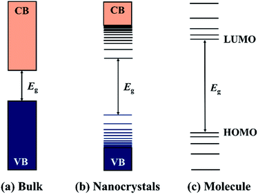
Semiconductor nanocrystals (NCs) are small crystalline particles which are typically synthesised with dimensions in the range of 1–100 nm. Since the discovery of nanocrystals embedded in glasses in the early 1980s, they have attracted considerable attention as an important component of materials. Semiconductor materials are characterised by their band structures (direct or indirect) and a band gap energy (Eg) that falls within a range of between 0 < Eg < 4 eV, and can be thought of as the minimum energy required to excite an electron from the valence band (VB) to the conduction band (CB). Furthermore, if one dimension of a semiconductor is smaller than the Bohr exciton radius of the material, the band structure will be modified and blue shifted to higher energy by the quantum confinement effect.1–5 In the limit of very small particle size, the so-called strong confinement regime, quantized levels appear, which is distinct with the continuous band of bulk counterparts and shows characteristics of the discrete molecular semiconductors (Fig. 1). The quantum size effect opens up possibilities for the fine-tuning of the band structures and thereby the optical and electrical properties of semiconductor NCs by simply controlling their sizes. Apart from the size-effect, the physical and chemical properties of semiconductor NCs are highly dependent on their compositions, shapes, structures, and surface chemistry, which have enabled semiconductor NCs to be used as active materials in various applications and fields.6–9To obtain high quality NCs with controllable physical or chemical properties, great efforts have been devoted to develop useful synthetic approaches for producing high quality, crystalline semiconductor NCs. Generally, according to the state of the reaction medium, the synthetic routes can be divided into the vapour-phase approach, solid-phase approach, liquid-phase approach, and the two-phase approach. Techniques such as ball milling,10 chemical vapour deposition (CVD),11,12 metal–organic vapour chemical deposition (MOCVD),13 molecular beam epitaxy (MBE),14–16 magnetron sputtering,17 laser ablation,18 etc. have also been developed for the synthesis of semiconductor NCs. However, due to certain instrumental and precursor limitations, vapour- and solid-phase approaches are often unsuitable for the fine-controlled synthesis of high quality NCs. In contrast, the liquid-phase approach has been proven as an efficient route to achieve well-defined semiconductor NCs. Semiconductor NCs synthesised by the liquid-phase approach are also referred to as colloidal semiconductor nanocrystals (CS-NCs) and are often dispersed in suitable solvents with the aid of capping ligands or surfactants. CS-NCs have attracted considerable attention due to their tunable energy structures, high optical absorption coefficients, large dipole moments, and the potential multiple exciton generation properties. Additionally, these stable suspensions possess advantages for direct application involving solution-based techniques such as spin-coating, inkjet printing, and roll-to-roll casting.6 These techniques mentioned are considered particularly attractive to large-scale device manufacturing, due to their low fabrication cost and ultrahigh throughput.19,20 Based on the types of reaction media, the liquid-phase approach can be further divided into three types: the aqueous-based approaches, organic-based approaches, and the aqueous–organic approaches. The aqueous approaches such as the chemical precipitation method2–4,21,22 and hydrothermal methods23–25 have the advantage of using environmentally friendly and biocompatible solvents. However, these methods are usually incompatible with efficient morphology control of NCs due to the mild reaction temperatures.26 In main point of comparison between the aqueous approach and the non-aqueous method is that the latter employs high boiling organic solvents, which enables the fine-controlled synthesis of CS-NCs. The particle sizes and shapes can be simply tailored by exploiting kinetically control over the nucleation and growth processes with the aid of organic ligands.27–30 In the past few decades, various non-aqueous methods have been developed, such as the hot-injection method,31 non-injection method32–34 and the solvothermal method using autoclaves.35–37 For the aqueous–organic approach, reactants are often dissolved in separate phases and solid nanocrystals are formed at the interface of aqueous and organic media. Therefore, this approach can also be referred to as an interface-mediated method or liquid–solid–solution (LSS) method.38–40 This method was originally introduced by Li38 and An41 et al. in 2005 and successfully applied for the synthesis of a wide variety of nanocrystals including novel metals, semiconductors, and even polymer nanoparticles.39 Nanocrystals prepared by the interface-mediated method are often spherical particles or common shapes favoured by their crystal structures. Precisely control over their shapes and exposed crystal facets is a challenge owing to the mild reaction conditions employed.26
Although a number of excellent reviews and book chapters have reported the synthesis of various CS-NCs,6,26,27,40,42–48 few of them focus on the organic-based approaches. Here, we present an overview of the state-of-the-art research for the controlled synthesis of CS-NCs, including the surface chemistry of nanocrystal surfaces. This review is divided into four main sections. In the first section, we describe the general formation mechanism of CS-NCs and the size-controlled synthesis of widely studied metal oxide/chalcogenide NCs. We summarise the factors that affect the particle size and distributions, such as the reaction temperature, precursor concentration, and ligand types. In the second section, we focus on the surface chemistry and passivation of CS-NCs, which have emerged as an important and active research field in recent years, because the properties of NCs are strongly influenced by the surface atomic conditions. In the next section, we present the facet-controlled synthesis of CS-NCs, also mainly focusing on metal oxide/chalcogenide NCs. It will be seen that the favoured exposed facets of NCs are closely related with their phase structures. At last, we highlight recent progress on the phase-controlled synthesis of CS-NCs in the fourth section.
2. Size control of CS-NCs through hot-injection and non-injection methods
In the past three decades, the tuneable physical and chemical properties generated by the quantum size effect in CS-NCs have attracted considerable attention, leading to strong interest in new innovations and developments of various synthetic approaches. When the diameters of NCs are smaller than the size of the material's exciton Bohr radius (usually in the range of 1–10 nm), the NCs are often referred to as quantum dots (QDs) and since the properties of QDs are fundamentally determined by the size effect, size-controlled synthesis of colloidal QDs has been one of the hottest research areas for the better part of two decades now. Before discussing specific details of size-controlling strategies, it is necessary to be aware of the general procedure and the reaction mechanism to be considered for the synthesis of NCs. The formation process of NCs has been known for a long time and basically consists of two stages, i.e. a nucleation stage and crystal growth stage according to the model of LaMer,49 as shown in Fig. 2. Reaction precursors are initially dispersed or dissolved in proper solvents, followed by the generation of monomers from the chemical reaction between precursors. As the concentration of monomers increase to the super-saturation level, nuclei will be formed by the aggregation and self-nucleation of monomers. With the continuous aggregation of monomers on these pre-existing nuclei, the growth process of nanocrystals occurs until the concentration of monomers drops to below the critical level. It should be noted that new nuclei are also formed during the growth of nanocrystals, which often results in a widening size distribution of the nanocrystals. Narrowing the size distribution to the ideal limitation is often the prime consideration with size control of CS-NCs.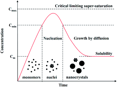 | ||
| Fig. 2 Schematic illustration of the nucleation and growth process of nanocrystals in solution: precursors are initially dissolved in solvents to form monomers, followed by the generation of nuclei and the growth of nanocrystals via the aggregation of nuclei (adapted with permission from ref. 48, copyright 2011, InTech). | ||
To control the size and size-distribution of CS-NCs, the following reaction parameters are important concerns: (i) the reaction temperature and time, (ii) the injection temperature of the reactant in the case of hot-injection methods, (iii) the reactivity and the concentration of precursors, (iv) the effect of solvent, surfactant, and pH, etc. The size distribution of nanocrystals is highly correlated to the kinetics of nucleation and growth processes. The nucleation stage can occur separately from the growth or be allowed to take place at the same time as growth. Since contemporaneity of nucleation and growth gives poor size distribution, the strategy of separating nucleation and growth is often applied to narrow the size distribution. In this strategy, a burst nucleation is often triggered by injecting precursors into solvents at high temperature, followed by a reduction of the reaction temperature to separate nucleation and growth. In 1993, this method was introduced by Murray and coworkers for the synthesis of monodisperse and high-quality cadmium chalcogenide nanocrystals.31 The synthesis was based on the reaction between organometallic precursors and chalcogenide sources in organic solvents. In this work, dimethyl cadmium (Cd(CH3)2) was used as a Cd source; and bis(trimethylsilyl) sulphide ((TMS)2S), bis(trimethylsilyl) selenide ((TMS)2Se), and bis(tert-butyldimethylsilyl) telluride ((BDMS)2Te) were used as the chalcogenide source. A mixture of tri-n-octylphosphine (TOP) and tri-n-octylphosphine oxide (TOPO) was used as the solvent, which is stable at high temperature (over 300 °C). The cadmium precursors were injected rapidly into the hot organic solvent at 300 °C, and allowed to react at desired temperatures. The average size of CdSe NCs was controlled within the range of 12–115 Å by adjusting the reaction temperature (Fig. 3). This approach involving the rapid injection of precursors into a hot solvent, referred to as the hot-injection method, has proven to be as an effective method for the synthesis of CS-NCs.
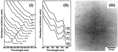 | ||
| Fig. 3 (i) The optical absorption spectra of CdSe NCs dispersed in hexane with the size ranging from ∼12 to 115 Å. (ii) The optical absorption spectra of CdSe NCs: (a) before size-selective precipitation; (b) after one cycle size-selective precipitation from the growth solution with methanol; (c) after dispersion in 1-butanol and second size-selective precipitation with methanol; (d) after a final size-selective precipitation from 1-butanol/methanol. (iii) The transmission electron microscope (TEM) image of CdSe NCs with size around 35.0 Å ± 5% (reproduced with permission from ref. 31, copyright 1993, American Chemical Society). | ||
To improve the size distribution of as-prepared NCs, the hot-injection method is often followed by post-treatments, such as rapid quenching of the reaction or size-selective precipitation. For example, in the above mentioned work,31 the as-prepared cadmium chalcogenide NCs were dispersed in 1-butanol, followed by the addition of methanol until opalescence persisted. Then the mixture was centrifuged, left smaller nanocrystals in the supernatant while larger ones could be removed in the precipitate. A comparison of the absorption spectra of CdSe NCs before and after size-selective precipitation is shown in Fig. 3. After several precipitation cycles, the size distribution was reported to be reduced from 10% to 5% standard deviation.
Although the size-selective precipitation is effective in narrowing the size distribution of NCs, it is time-consuming and wastes products with undesired particle sizes. In order to further improve the synthetic method, close examination of the growth behaviour of NCs is warranted. According to the authoritative study on the size-distribution control of colloidal NCs, the growth stage of NCs possesses two types of possibilities, i.e. “diffusion-controlled growth” and “reaction-controlled growth”.50 In the first case, the chemical reaction occurs so fast that the crystal growth rate is controlled by monomer diffusion through the reaction medium/solvent. Based on the Fick's first law,51 the growth rate (dr/dt) of NCs can be derived and written as:
| dr/dt = DVm(1/r + 1/δ)(Sb − Sr) | (1) |
In the case of “reaction-controlled growth”, the particle growth is mainly controlled by the surface reaction of monomers. The growth rate of NCs is determined by the relative rate of nucleation and the growth rate of monomers on particle surfaces. If the two-dimensional growth of nuclei on particle surfaces is extremely fast compared to the nucleation of monomers in solution, the particle surfaces will be covered by a nuclei layer. In this case, the particle growth rate is proportional to the surface area of the individual particle, and the size distribution will broaden with the progress of particle growth. Fortunately, this case can only occur at the very early stage of particle growth, otherwise the particle size would grow to be infinite. In most cases, the particle growth is dominated by the direct nucleation of monomers on particle surfaces and the crystal growth rate can be written as:
| dr/dt = kVm(Sb − Sr) | (2) |
Sr = Sb![[thin space (1/6-em)]](https://www.rsc.org/images/entities/char_2009.gif) exp(2σVm/rRT) exp(2σVm/rRT)
| (3) |
When the size-dependence of particle solubility is considered based on the Gibbs–Thomson equation (eqn (3)),50 the crystal growth rate and size distribution will be further modified. In the case of “diffusion-controlled growth”, they can be rewritten as:
| dr/dt = KD(1/r* − 1/r)/r | (4) |
d(Δr)/dt = KDΔr(2/![[r with combining tilde]](https://www.rsc.org/images/entities/i_char_0072_0303.gif) − 1/r*)/ − 1/r*)/![[r with combining tilde]](https://www.rsc.org/images/entities/i_char_0072_0303.gif) 2 2
| (5) |
![[r with combining tilde]](https://www.rsc.org/images/entities/i_char_0072_0303.gif) the average particle radius. According to eqn (4), the crystal growth rate is positive for the particles larger than the critical size r*, but negative for those smaller than critical size. When the ratio of average size to the critical size is higher than two (
the average particle radius. According to eqn (4), the crystal growth rate is positive for the particles larger than the critical size r*, but negative for those smaller than critical size. When the ratio of average size to the critical size is higher than two (![[r with combining tilde]](https://www.rsc.org/images/entities/i_char_0072_0303.gif) /r* > 2), the size distribution will be narrowed instead of broaden (eqn (5)).
/r* > 2), the size distribution will be narrowed instead of broaden (eqn (5)).
Similarly, the particle growth rate and size distribution in the case of “reaction-controlled growth” can be rewritten as (assuming the reaction is first-order):
| dr/dt = KR(1/r* − 1/r) | (6) |
d(Δr)/dt = KRΔr/![[r with combining tilde]](https://www.rsc.org/images/entities/i_char_0072_0303.gif) 2 2
| (7) |
The above theories introduced by Sugimoto in 198750 provide fundamental guide for experimental activities on the controlled growth of NCs. In 1998, Alivisatos and coworkers experimentally investigated the kinetic growth and the particle size distribution control of semiconductor nanocrystals.52 Fig. 4a shows the time evolutions of the size and size distribution of CdSe NCs prepared by a hot-injection method using cadmium complex as the cadmium source. It demonstrated the diffusion-controlled growth behaviour of II–VI colloidal nanocrystals. At the initial stage after injection, nucleation took place immediately and the average size increased rapidly from 2.1 to 3.3 nm, with a size distribution that focused from 20% to 7.7%. During this period, the monomer concentration was high, therefore the particle size was larger than the critical size and under these conditions, size-focusing occurs. As the monomer concentration decreases, particles grow slowly, and the critical size becomes larger than the average particle size. This resulted in the shrinking of smaller particles with size distribution being broadened to 10.6%, which is called “defocusing” of particle sizes.53 The focusing and defocusing process of size distribution are illustrated in Fig. 4b. To increase the particle size while also maintaining a narrow size distribution, a secondary injection was introduced when the monomer concentration dropped to a certain level. As shown in Fig. 4a, the size distribution of NCs was re-focused after the secondary injection during the reaction.
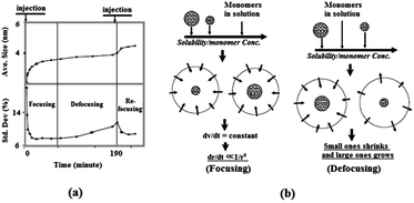 | ||
| Fig. 4 (a) Temporal evolution of the size distribution of CdSe NCs prepared by a hot-injection method, including a secondary injection during the reaction. (b) Illustration of the focusing and defocusing of size distribution observed in (a) (reproduced with permission from ref. 52, copyright 1998, American Chemical Society, and ref. 53, copyright 2005, Springer). | ||
Now while careful studies have shown that fine control over the size and size distribution of NCs by certain strategies or methods is realisable. The reproducibility and feasibility of using these approaches in routine preparations of NCs remain as central concerns for researchers. For the above-mentioned method, the organometallic precursors used are extremely toxic and unstable at ambient conditions, which hinders reproducible results. This realization motivated researchers to trial alternative precursors which are stable, low-cost and are less toxic chemicals. In 2001, air-stable CdO was introduced as the Cd precursor for the synthesis of cadmium chalcogenide NCs by Peng et al.54,55 Compared to organocadmium compounds, CdO is less toxic and more stable in ambient conditions. The quality of the obtained cadmium chalcogenides NCs produced by this method was found to be comparable to that of the best results reported by the organometallic method. The exclusion of organometallic cadmium has the advantage of avoiding strongly air-sensitive chemicals from the synthesis, enabling NCs to be prepared without using a glovebox, which could be considered to be an important step toward green-chemistry synthesis of cadmium chalcogenide NCs.
Similar hot-injection methods have also been applied to the synthesis of lead chalcogenides. For example, PbSe NCs were prepared by Murray and coworkers by injection of lead oleate (Pb(OAc)2) and trioctylphosphine selenide (TOPSe) into a diphenylether solution at 150 °C.56,57 Monodisperse PbSe NCs with tunable size from 3.5 nm to 15 nm were obtained by controlling the growth temperature within the range of 90 to 220 °C. In 2003, the hot-injection method was extended from the previous cadmium chalcogenides and PbSe synthesis to the preparation of PbS NCs by Hines and Scholes.58 In their method, a mixture of lead oxide (PbO), oleic acid (OA), and 1-octadecene (ODE) was heated to 150 °C under Ar, followed by the injection of a solution of (TMS)2S in ODE. After the hot injection, the temperature was either maintained at 80–140 °C or cooled slowly to room temperature, depending on the desired particle size. Subsequent approaches explored use of various lead precursors, chalcogenide precursors, and solvents.36,59,60
Following the synthesis of binary Cd and Pb chalcogenide NCs, the hot-injection method was effectively employed to fabrication of ternary and quaternary metal chalcogenide NCs, such as CuInS(Se)2 (CIS), Cu2SnS(Se)3 (CTS), and Cu2ZnSnS(Se)4 (CZTS). Compared to binary chalcogenides, ternary and quaternary copper chalcogenide NCs have high flexibility in terms of tuning the chemical composition and band structure without involving toxic heavy metals, such as Cd and Pb. Another advantage of NCs such as CZTS is that they are based on earth-abundant elements, and could be considered as promising alternatives for replacing Cu(In, Ga)Se2 (CIGS) in thin film solar cells. The initial synthesis of CIS NCs by the hot-injection method was reported in 2008 by several research groups.61–65 Generally, these NCs were prepared by injecting either metal precursors (e.g. metal halides, metal acetate, metal acetylacetonate, metal diethyl dithiocarbamate, etc.), chalcogenide precursor (e.g. S, Se, TMS, TMSe, DDT, etc.) or coordinating solvents (OLA, TOP, etc.) into another hot reaction medium. The size of CIS NCs was controlled within the range from 2 to 25 nm by simply changing the reaction temperature or choosing precursors with different reactivity. It should be noted that due to the structural complexity of ternary compounds, the obtained CIS NCs are often non-stoichiometric and contain multiple crystal phases. This situation offers the opportunity of finely control over the crystal structures of NCs, which will be discussed in the last section of this work. After the report of ternary CIS NCs, quaternary chalcogenide NCs such as CZTS was soon prepared by the hot-injection method in 2009.66–68 CZTS NCs with sizes in the 15–25 nm range were obtained by injecting an oleylamine (OLA) solution of sulfur into another hot OLA solution containing copper acetylacetonate, zinc acetylacetonate and tin(IV) bisacetylacetonate dibromide.66 The control over crystal sizes was also investigated in subsequent literatures by modifying the precursor, temperature, solvent, etc.69,70 Further discussion about quaternary CZTS NCs synthesis will be made in the section of phase-controlled synthesis.
The hot-injection method has also been extended to the synthesis of other CS-NCs, such as metal oxides nanocrystals. In 1999, this method was first time adapted by Trentler et al. for the synthesis of titanium oxide (TiO2) NCs.71 The procedure involved the rapid injection of titanium alkoxide into a hot solution containing TiCl4, TOPO, and heptadecane, followed by maintaining the temperature at 300 °C for 5 min. Nearly spherical anatse TiO2 NCs were obtained with particle size less than 10 nm. In addition to TiO2 NCs, the hot-injection method was also reported for other metal oxides, such as ZnO (injecting sodium hydroxide into the ethanolic solution of zinc acetate at 80 °C),72 ZrO2 (injecting zirconium(IV) isopropoxide into a mixture of ZrCl4, TOPO and heptadecane at over 300 °C),73 CeO2 (injecting cerium benzoylacetonate solution into the OLA solvent at 250 °C),74 and WO3 (injecting tungsten(V) ethoxide into a mixture containing OA and trioctylamine at 315 °C).75 More examples about metal oxide prepared by the hot-injection method in organic media can be found in various reviews and book chapters.48,76–78
Apart from the hot-injection method, the non-injection or directly heating-up methods have also been developed for the synthesis of CS-NCs. In non-injection methods, the separation of nucleation and growth is realized by slowly heating up the solution in the presence of particular precursors. The precursors should meet the requirement that they have negligible reactivity at a low temperature, but significant reactivity at elevated temperatures. When precursors are heated up to a certain temperature, a burst nucleation will occur followed by the growth of nanocrystals, which is similar to the process in hot-injection methods. Compared to the hot-injection method, non-injection methods are far simpler without the injection step, this provides an alternative way to obtain high-quality CS-NCs at relatively low temperatures that is environmentally friendly and suited to scale-up. In 2005, CdSe and CdTe NCs prepared by the non-injection method was reported by Cao and coworkers.79 In their method, high-quality monodisperse CdSe NCs with size standard deviation less than 5% were obtained by heating up a mixture of cadmium myristate, selenium powder, and ODE. It was noted that selenium powder was insoluble in the solvent at low temperature, but soluble when the temperature was raised up to 220 °C, triggering the reaction. Subsequently, size-controlled CdSe nanocrystals were prepared by the same group using less toxic selenium dioxide (SeO2) as the selenium source.80
Likewise, colloidal PbS NCs were prepared by the non-injection method at low temperature in 2009.81 A mixture of PbO, OA, and ODE was heated to 120 °C and then cooled down to room temperature, followed by the addition of (TMS)2S and followed by heating again to 40–120 °C. PbS NCs of variable size were obtained by using different growth temperatures, and it was suggested that the narrowing of size distribution took place at 70–80 °C. In a recent study, it was found that PbS NCs could also be obtained over a wide temperature range from −25 to 240 °C.82 In this method, a lead precursor solution was prepared by mixing PbO, OA, and fatty amine at room temperature, while sulfur solution was prepared by mixing S, fatty amine, and phenyl ether. For the synthesis at −20 to 0 °C, lead and sulfur solutions were frozen into solids and then crushed and mixed together. The two solids gradually became a mud-like mixture and it was confirmed that black PbS NCs were formed, following extraction by methanol and precipitation by acetone. Recently, a general non-injection method for the synthesis of metal sulphide NCs was reported by Li and coworkers.26,83 Fig. 5a illustrates the general procedure and a proposed mechanism of metal sulphide NCs synthesis prepared by the non-injection method. This synthesis consists of two steps, first metal thiolate intermediates were generated from metal salts and thiols, followed by their decomposition at high temperature. By directly heating the mixture of inorganic metal salts and alkylthiol, with or without capping ligands, high-quality Ag2S, Cu2S, PbS, Ni3S4, CdS, and ZnS nanocrystals were obtained (Fig. 5b–g). For example, PbS NCs were prepared by mixing lead acetate and dodecanethiol (DDT) at room temperature and heating at 220 °C. The average size of PbS NCs was simply controlled from 30 to 120 nm by adjusting the Pb2+ concentration from 0.033 to 0.167 mol L−1 in DDT solvent. It was observed that a low Pb2+ concentration resulted in small nanocrystals, while a high concentration gave large ones. This was due to the fact that high precursor concentration could accelerate the growth rate of colloidal nanocrystals.
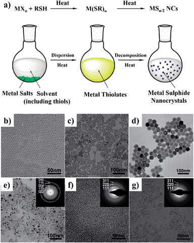 | ||
| Fig. 5 (a) Schematic illustration of the “non-injection” method for the synthesis of metal sulphide NCs. (b–j) Representative TEM images of NCs obtained by the “non-injection” method: (b) Ag2S; (c) Cu2S; (d) PbS; (e) Ni3S4; (f) CdS; and (g) ZnS. The insets in (e–g) are the corresponding selected area electron diffraction (SAED) patterns (adapted with permission from ref. 26, copyright 2011, Royal Society of Chemistry). | ||
Ternary and quaternary chalcogenide compounds, such as CIS and CZTS NCs have also been prepared by the non-injection method over the last few years. For the typical synthesis of chalcopyrite CIS NCs, CuI, In(OAc)3, and DDT were mixed in the ODE solvent, followed by addition of OA as a capping ligand and heated up to 200 °C under Ar.33 The particle size was controlled from 3.5 to 7.3 nm with varying reaction times from 20 to 120 min (Fig. 6). The synthesis could be scaled up to obtain multi-gram CIS NCs with product yield around 80–90%. Similarly, wurtzite CZTS NCs have also been prepared through the non-injection route, which involved the thermolysis of metal dithiocarbamates in the presence of surfactant.34 For example, CZTS NCs were obtained by degassing a mixture of copper(II) diethyldithio-carbamate (Cu(dedtc)2), zinc(II) diethyldithiocarbamate (Zn(dedtc)2), tin tetra-(diethyldithiocarbamate) (Sn(dedtc)4), hexadecanethiol, and trioctylamine at 100 °C, followed by heating at 250 °C for a fixed time depending on the desired final particle sizes.
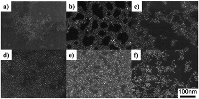 | ||
| Fig. 6 Scanning transmission electron microscopy (STEM) images of CuInS2 NCs with diameters of (a) 3.5 ± 0.4, (b) 4.6 ± 0.6, (c) 5.2 ± 0.7, (d) 5.6 ± 0.7, (e) 6.1 ± 1.1, and (f) 7.3 ± 1.4 nm. These nanocrystals were prepared under identical conditions with varying reaction times of 20, 30, 45, 60, 90, and 120 min, respectively (reproduced with permission from ref. 33, copyright 2010, American Chemical Society). | ||
It is notable that organic species are often employed in the synthesis of high-quality nanocrystals using the aforementioned approaches, i.e. either hot-injection or non-injection methods. The organic molecules either exist as additional surfactant, chelating with precursors to form complexes, or as solvents for chemical reactions during the synthesis of NCs. In any case, the surfaces of obtained nanocrystals are stabilized by these organic molecules, which are often referred to as capping ligands. It has been found that capping ligands not only stabilize the nanocrystal surfaces, but also determine the geometrical properties of nanocrystals, such as the particle size and size distribution. For example, ZnSe nanocrystals have been prepared by heating the mixture of ZnO, SeO2 and ODE at 280 °C in the presence of OA ligand.84 ZnSe nanocrystals with controllable average size ranging from 5.0 nm to 8.4 nm were obtained, as shown in Fig. 7. It was observed that under the same conditions of reaction temperature and time, larger nanocrystals were obtained by increasing the amount of OA. It was suggested that the reactivity of the zinc precursor was decreased by the OA amount, resulting in a lower nuclei concentration but high monomer concentration, thus leads to a faster growth of nanocrystals. Another example of the ligand effect was observed in the synthesis of PbS NCs. As shown in Fig. 8, monodisperse PbS NCs were obtained when octylamine was used as the capping ligand, independent of the reaction temperature. However, when a mixture of octylamine and oleylamine was used as the capping ligand, PbS clusters were obtained instead, resulting from the aggregation of individual spherical particles.82 These results demonstrated the tremendous influence capping ligands have on the morphology of CS-NCs, which is essential for various applications.
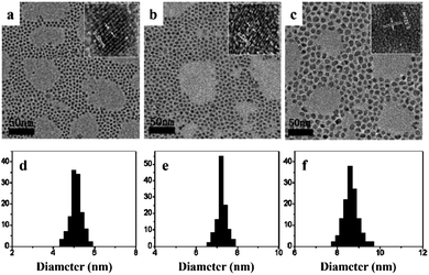 | ||
| Fig. 7 TEM and high-resolution transmission electron microscopy (HRTEM) images of the as-prepared ZnSe NCs synthesised at 300 °C with different amount of OA as the capping ligands. The average particle size is (a) 5.0 nm, (b) 7.2 nm, and (c) 8.4 nm. (d)–(f) are the corresponding size-distribution histograms obtained from (a–c), respectively (reproduced with permission from ref. 84, copyright 2010, Royal Society of Chemistry). | ||
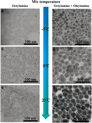 | ||
| Fig. 8 TEM images of PbS NCs synthesised by non-injection method using an individual amine (left column) and mixed amines (right column) as the capping ligands at different reaction temperatures: (a and b) −5 °C; (c and d) 0 °C; and (e and f) 25 °C (reproduced with permission from ref. 82, copyright 2013, Royal Society of Chemistry). | ||
The ligand effect has also been observed for the synthesis of metal oxide nanocrystals. For example, ZnO NCs with controllable sizes have been prepared in organic solvents in the presence of various capping ligands, especially those with long alkyl-chains, such as OA, TOPO, dodecylamine (DDA), hexadecylamine (HDA), and tert-butyphosphonic acid (TBPA), etc.85–88 During research into preparation of small size ZnO nanocrystals, our group investigated the effect of capping ligands on ZnO particle sizes using both experimental and theoretical approaches. Organic molecules with different structural characteristics were used as capping ligands, i.e. multi-chelating small molecules versus long alkyl chain amine, thiol, and phosphine oxide and compared with traditional ligands such as DDT, HDA, and TOPO. The small molecule tris(hydroxymethyl) aminomethane (THMA) was found to be more effective at stabilizing ZnO nanoparticles (NPs) and narrowing the size distribution. The TEM images with average particle sizes and the corresponding simulated structures of ligand-capped ZnO are shown in Fig. 9. It was observed that the average diameter of THMA-capped ZnO NPs was 1.3 nm, which is considerably smaller than average diameter prepared using the same synthesis technique with traditional ligands. This behaviour could be explained by comparing the theoretical binding energy between each ligand and ZnO surfaces. The binding energy obtained with THMA and ZnO is much higher than other ligands, the effect of which is to hinder the rapid growth and aggregation of ZnO NPs.72 Fig. 10 illustrates the various adsorption forms of different organic ligands on ZnO surfaces.
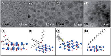 | ||
| Fig. 9 (a–d) TEM images of varied-sized ZnO NPs prepared from zinc acetate and sodium hydroxide in ethanol in the presence of different ligands: (a) THMA, (b) TOPO, (c) DDT, and (d) HDA. (e)–(h) are the corresponding optimised surface structures of ZnO NPs capped with ligands used in (a and b), respectively (adapted with permission from ref. 72, copyright 2012, Springer). | ||
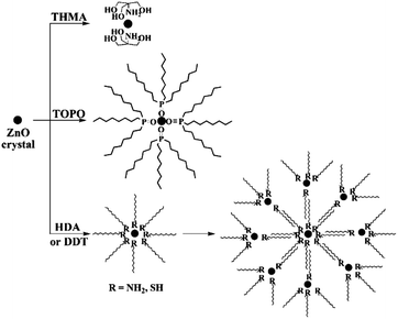 | ||
| Fig. 10 Schematic illustration of the adsorption forms of various capping ligands (THMA, TOPO, DDT, HDA) on ZnO particle surfaces (reproduced with permission from ref. 72, copyright 2012, Springer). | ||
3. Surface chemistry and passivation of CS-NCs
Besides the quantum size effect, surface chemistry also plays a significant role in the physical and chemical properties of CS-NCs. Despite of the high crystallinity of CS-NCs prepared in hot solutions, they still contain many defects, especially on their surfaces. Compared to the interior atoms of a pure nanocrystal, the surface atoms have a lower coordination number which therefore leads to unsaturated dangling bonds and substantial reconstructions of atomic positions. The energy levels corresponding to the electronic state or surface state of dangling bond orbitals lie within the forbidden region between the electronic band gaps of bulk solids. Electrons or holes will be trapped by these mid band gap states, thus “degrading”, or at least substantially altering (compared to bulk-behaviour) the optical, electrical, magnetic, and thermal properties of these materials. The smaller the nanocrystals, the more surface defects they will have, because of the higher surface-to-volume ratio. Therefore, the quantum size effect and corresponding properties often come with the price of more surface defects.2,89 For example, the luminescence quantum yield (QY) of the high-quality CdSe NCs prepared by Murray et al. in 1993 was only around 9.6%, which is mainly due to the surface trapping states.31 Again, the optoelectronic applications of PbSe90 and PbTe91 NCs have for a long-time been hampered by their instability under ambient conditions and therefore surface trap effects, although they possess superior properties to the PbS counterpart.92Consequently, surface passivation is often considered necessary in CS-NCs synthesis to bond with and thereby raise the coordination number of the surface unsaturated atoms and eliminate the energy levels or traps within the semiconductor's band gap. In order to improve their optical and electronic properties for applications such as light-emitting diode, bio-labelling, and photovoltaics, several passivation approaches have been developed, including covering the CS-NCs with a wider-gap material to form a “core/shell” type structure or terminating the dangling bands with proper capping ligands. Forming core/shell structures has been considered as an effective strategy to eliminate surface traps of CS-NCs by completely passivating both the cationic and anionic species, thus eliminating the associated traps in both valence and conduction bands. In 1987, this strategy was first-time reported by Spanhel et al. for the passivation of CdS in an aqueous solution.22 The photoluminescence quantum yield (PL-QY) of as-prepared CdS-core was only about 1%, but this was raised up to 50% after the introduction of excess Cd ions and NaOH. It was explained that a thin layer of Cd(OH)2 shell formed on the CdS-core surfaces, which created a barrier for excited electron–hole pairs and eliminated the surface recombination traps.
Typical studies of core/shell structures are based on a two-step procedure, i.e. the synthesis of core material, followed by the growth of the shell material. In 1996, Hines et al. reported the synthesis of ZnS-capped CdSe NCs using organometallic reagents by the two-step method.93 Specifically, CdSe seeds were initially synthesised by injecting the Cd/Se/TOP stock solution into the TOPO solvent at 350 °C, followed by the injection of Zn/S/TOP solution in 5 portions at approximately 20 s intervals. After the reaction, the obtained CdSe/ZnS core/shell NCs were purified by precipitation and washed several times with methanol, and finally dispersed into chloroform. For this method, the growth temperature of ZnS-shell is critical. Low temperature produces low quality ZnS, while high temperature will result in the continued growth of CdSe seeds via the Ostwald ripening process, that leads to an increase of size distribution.94 Another critical parameter is the concentration of Zn/S stock solution and its addition rate to the CdSe solution. Low concentration and slow injection ensure the heterogeneous growth of ZnS onto CdSe seed surfaces, instead of the homogeneous nucleation of ZnS. It was also found that the PL-QY of CdSe/ZnS NCs was dependent on the shell thickness, with maximum value when ∼1.3 monolayer ZnS was formed. It was suggested that the reduction in PL-QY with thicker ZnS-shell was attributed to the lattice mismatch between CdSe and ZnS, and the formation of defects in the ZnS shell.
Due to the sensitivity to temperature and poor reproducibility of the shell growth by simultaneously injecting shell precursors into the solution of core seed, a new technique named as “successive ion layer adsorption and reaction” (SILAR) method was subsequently developed. In SILAR methods, the growth of the shell was achieved by alternating injection of the cationic and anionic precursors into the solution of core nanocrystals. The principle of the SILAR method was demonstrated by Peng et al. in 2003 for the synthesis of CdSe/CdS core/shell NCs.95 It was suggested that high temperature around 220–240 °C was essential for the formation of CdS shell using CdO and elemental S as the precursors. The size distribution of the CdSe/CdS NCs was maintained during the growth of CdS shell. Following the high temperature SILAR method, a modified approach – “thermal cycling coupled single precursor” (TC-SP) method was developed by the same group in 2010.96 TC-SP uses a single precursor for the synthesis of shell materials. This not only simplified the synthetic procedures, but also permitted a reduced growth temperature due to the high reactivity of single precursors. The reduction of temperature can eliminate the competing homogeneous nucleation side-reaction of shell materials. Fig. 11a exhibits the synthetic procedure of CdS/ZnS core/shell NCs via this TC-SP method. Single precursor zinc diethyldithiocarbamate (Zn(DDTC)2) was injected into the solution with in situ purified CdS core NCs, followed by its decomposition at around 160–200 °C to form the ZnS shell. The thickness of ZnS was monitored by the intensity of the fluorescence peaks shown in Fig. 11b. The PL-QY of the CdS/ZnS NCs prepared by the TC-SP method was found to be higher than those made by traditional SILAR method (Fig. 11c). Recently, CdSe/CdS core/shell NCs have also been synthesised by the TC-SP method at even lower temperature (100–140 °C) for the growth of CdS shell with the assistance of a primary amine.97
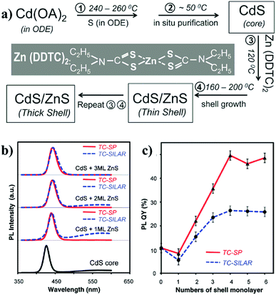 | ||
| Fig. 11 (a) The reaction scheme for the synthesis of CdS/ZnS core/shell NCs via the TC-SP method. (b) PL properties of the CdS/ZnS core/shell NCs in comparison to the initial CdS core NCs. (c) The comparison of the PL-QY of CdS/ZnS NCs grown by both TC-SP and thermal-cycling coupled SILAR (TC-SILAR) methods (reproduced with permission from ref. 96, copyright 2010, American Chemical Society). | ||
For the effective passivation of CS-NCs with inorganic shells, choice of the shell materials is critical, they should not only have small lattice mismatch with the core's surfaces, but they also provide a sufficient potential barrier for any photoexcited electrons and holes inside the core NCs. In most cases it is a challenge to meet the ideal requirements for a single pure semiconductor. Therefore, alloyed or gradient shells have been recently developed for the passivation of CS-NCs. The rationale for this approach is that the final product will possess the combined benefits of the different shell materials. For example, CdSe/CdZnS core/shell NCs were synthesised by exploiting the different growth kinetics of CdS and ZnS materials. To form the CdZnS shell, a purified CdSe core solution was injected into a hot mixture containing Cd and Zn precursors, followed by the injection of S precursor and maintenance at 300 °C for certain time.98 After the coating of CdZnS shell, the PL-QY of these CdSe NCs significantly improved from 9.2% to 89%. CS-NCs coated with alloyed shells can also be easily prepared by a scalable single-step, non-injection approach. For instance, high-quality core/shell NCs (CdS/CdZnS, CdSe/CdZnS, and CdTe/CdZnS) have been obtained by directly heating up a mixture of CdO, Zn(NO3)2, and chalcogenide elements in ODE solvent.32 Fig. 12 illustrates the general synthetic procedure of these core/shell NCs through non-injection methods.
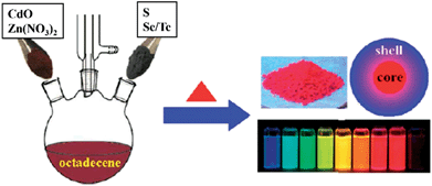 | ||
| Fig. 12 Schematic illustration for the synthesis of cadmium chalcogenide core/shell NCs through non-injection methods (reproduced with permission from ref. 32, copyright 2012, American Chemical Society). | ||
While inorganic shells have successfully passivated various CS-NCs, the interface with the homogeneous core material is transformed into a complex heterojunction, which can alter the carrier density of individual core NCs and the electron transport dynamics between NCs. In fact, it has been gradually realised that a full shell does not necessarily achieve a comprehensive or sufficient passivation of CS-NCs. An alternative approach is to saturate the dangling bonds on nanocrystal surfaces with capping ligands instead of a depositing a full shell. Ligand-binding can achieve both the surface passivation and superior charge transport at the same time.
A variety of capping ligands have been explored for the surface passivation of CS-NCs. Generally, three types of capping ligands, i.e. organic, inorganic, and atomic ligands have been employed, with stable and less sterically hindered species exhibiting enhanced performance. Typical organic passivation ligands include polymers,99–101 fatty acids,102 alkylamines,102–104 thiols,105 phosphide oxide compounds,72 etc. Polymers are often efficient nanocrystal stabilisers due to their hindrance effect, but do not generally achieve perfect enough surface passivation owing to their relatively low capping density. CS-NCs obtained from reaction solutions are often capped by organic molecules with long chains (8–18 carbons) in order to maintain the colloidal stability. These capping ligands can be exchanged with other ligands to achieve solubility in desired hydrophobic or hydrophilic solvents. Some specific ligands, such as amines have been found to confer an extra passivation effect to nanocrystal surfaces. For example, the PL-QY of as-prepared CdSe NCs (capped with TOPO) was measured to be in the range of 10–25%. After ligand exchange with dodecylamine (DDA), the PL-QY of these NCs was enhanced up to 40–50%, which was comparable to the values of CdSe/ZnS core/shell NCs.106 The improvement in PL-QY was attributed to the strong bonding of DDA to CdSe surfaces, which effectively passivated the surface trap states. It has also been found the electronic conductivity of PbSe NCs is determined by the passivating ligand/s alkyl chain length.107 This could be related with change of the average distance maintained between individual particles by the different ligand shells. Therefore, short organic capping ligands, such as pyridine, ethanedithiol (EDT), ethylenediamine (EDA), and mercaptocarboxylic acid (MPA) have been widely used for the passivation of CS-NCs. They could not only achieve effective passivation of NCs, but also reduce inter-particle spacing and form closely packed films for photovoltaic devices.108–113
Although tremendous improvements have been achieved for the surface passivation of CS-NCs, there are still some challenges and questions to explore. First, compared to pure inorganic systems, most organic ligands suffer drawbacks related to their oxidation and thermal degradation issues, which dramatically influence the stability and photoelectric properties of devices based on NCs capped with these ligands. In 2001, Peng et al. demonstrated the photochemical instability of thiols (including MPA) when they were used as capping ligands for CdSe NCs.114 It was found the thiol ligands on the surface of NCs could be gradually oxidised to disulfides, which were soluble in water, thus resulting in the precipitation of CdSe in aqueous solutions. Other organic ligands, such as amines have been reported to etch and oxidize CIS NCs, and deteriorate their optical and electrical properties.61,62,115,116 Second, the steric effect of organic ligands prevent them from fully passivating the unsaturated atoms on nanocrystal surfaces. Finally, when CS-NCs are assembled into films on substrates, these insulating organic ligands could result in cracks in films, which are not desired for device applications.
Hence, above considerations have motivated researchers to develop short, inorganic ligands or hybrid ligands for the passivation of CS-NCs. These promising inorganic ligands mainly include metal chalcogenide complexes (MCC),117–119 chalocogenide anions,120 thiocyanate anion,121 atomic ligands,122–126 etc. In 2009, Talapin et al. reported the preparation of MCC-capped NCs through ligand exchange method, as shown in Fig. 13a.117 These intelligent ligands could be converted into a semiconducting phase upon heat treatment, forming inorganic solids. They investigated the electron transport of In2Se42−-capped CdSe NCs and achieved electron motilities as high as 16 cm2 V−1 s−1, which was close to an order of magnitude higher than those organic-capped samples.119 Subsequently, the same group tested metal-free inorganic ligands such as chalcogenides and hydrochalcogenides (S2−, HS−, Se2−, HSe−, Te2−, and HTe−), mixed chalcogenides (TeS32−), OH−, NH2−,120 etc. Fig. 13b shows one example of these NCs capped with S2− ligands. These ligands significantly enrich the variety of surface passivation strategies for nanocrystals and open up promising opportunities for device integration of CS-NCs. Simultaneously, ammonium thiocyanate (NH4SCN) was introduced in 2011 as the capping ligand for a wide range of nanocrystals (Fig. 13c). It was shown that the conductivity of PbTe films was increased by 1013 after the treatment using NH4SCN, which was attributed to the enhanced interparticle coupling in nanocrystal solids.121 On the other hand, ions or atomic ligands have also attracted much attention in recent years, which possess similar advantages with abovementioned ligands. In fact, the passivation strategy using atomic ligands actually dates back to early in the last century, for instance when I− ions were used for the stabilization of AgI colloids.127,128 Recently, Sargent et al. used atomic ligands for the passivation of CS-NCs, especially PbS NCs. Two common strategies have been used to conduct the ligand exchange process for NCs: (i) solution exchange, and (ii) solid exchange. In the first case, atomic capping ligands are mixed with nanocrystal colloids to replace the insulating organic ligands on nanocrystal surfaces, followed by separation of atomic-passivated NCs. For the solid exchange, the initial solid films are assembled, followed by treatment with a solution containing the desirable ligands. Both cation (such as Pb2+, Cd2+) and anion (such as Cl−, Br−, and I−) ligands have been employed. To achieve efficient passivation, it is necessary to apply both ions and ligand exchange processes for CS-NCs. For example, a solution containing CdCl2, tetradecylphosphonic acid (TDPA), and OLA was initially injected into a PbS colloid to eliminate any surface defects associated with unpassivated sulfur surface anions. After purification, PbS colloid films were fabricated by a spin-coating method, followed by the solid exchange with a solution containing halide ligands and washing with non-solvent to remove extra ligands.122,124,125 Fig. 13d exhibits the synthetic procedure of PbS NCs including the passivation process using MClx (M is a metal cation). These atomic ligands have shown excellent passivation effect for PbS nanocrystals, achieving a record efficiency of 7.0% for fabricated solar cells.123
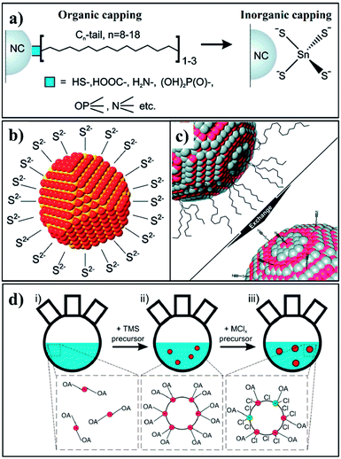 | ||
| Fig. 13 Schematics of (a) the ligand exchange process used for preparing MCC-capped NCs; (b) a nanocrystal capped with S2− ligands; (c) SCN−-capped NCs through ligand exchange; (d) synthetic procedure of PbS NCs including the metal halide passivation process (reproduced with permission from ref. 118, copyright 2010, American Chemical Society; ref. 120, copyright 2011, American Chemical Society; ref. 121, copyright 2011, American Chemical Society; and ref. 125, copyright 2013, American Chemical Society). | ||
4. Shape/facet control of CS-NCs
It has been known that physical and chemical properties of CS-NCs are not only related to crystal sizes and surface chemistry, but also associated with the particle's shapes. This is because the abundance of specific atomic structures exposed on the different crystal facets is directly dependent on particle shapes. Therefore, control over crystal shapes, especially the dominant facets in NCs has attracted much attention in last two decades. Very small NCs are often terminated by a variety of crystal facets possessing a roughly spherical shape, which is the thermodynamic stable morphology. However, each facet of a crystal has different growth behaviour due to the innate structural anisotropy of certain crystal structures. Faceted nanocrystals, therefore, can be synthesised by controlling the kinetics of growth of each facet (usually this is most clearly observed in systems with slow growth rates). Since the growth rate is relatively slow, average sizes of shape-controlled NCs are often in the range of 10–100 nm. It so happens that this size range is also favourable for the accurate characterization of certain exposed facet by techniques such as TEM.Due to the anisotropic property caused by the crystal field effect, semiconductor NCs have varied shape evolution and potentially different faceted-shapes, depending on their crystalline structures. For example, isotropic structures such as cubes are often favoured for nanocrystals with zinc-blende structure, which belongs to the cubic crystal system with an isotropic unit cells.129,130 In contrast, the unit cell of a wurtzite nanocrystal possesses a unique c-axis, which often favours anisotropic growth along this crystalline direction to form hexagonal, rod-shaped morphologies. Moreover, in the case of anatase nanocrystals, the unique anisotropic unit cell structure also favours the growth along the c-axis, leading to the formation of tetragonal prism or wire shaped nanocrystals. Nevertheless, apart from these thermodynamically favoured shapes, NCs exposed with high index facets tend to attract much more attention due to their high reactivity which could be harnessed in a variety of applications. The unit cells and the corresponding common facets of widely studied crystalline structures are shown in Fig. 14. For various nanocrystals, high index facets such as {101} and {111} facets are extensively investigated due to their unique properties. Facets with even higher index (e.g. {220}- or {311}-faceted zinc-blende ZnS nanocrystals131) are also available, but the crystal will tend to be spherical as the crystal index increases, which makes it difficult to identify them. This section will mainly focus on the controlled synthesis of metal chalcogenide/oxide NCs with well-defined exposed facets in organic media. More summaries for shape-controlled synthesis of colloidal nanocrystals can be found in a number of well-organised reviews.48,132–137
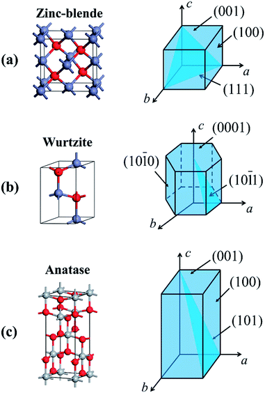 | ||
| Fig. 14 Unit cells and the corresponding schematic diagrams with common crystal facets of (a) zinc-blende structure, (b) wurtzite structure, and (c) anatase structure. | ||
On the basis of the characteristic of crystalline structures, the facet-controlled synthesis of CS-NCs can be realised by adjusting the reaction parameters (e.g. precursor concentration, temperature, and capping ligands) to modify the relative growth speed of each facet. Solution synthesis in organic media has been used to achieve certain desired dominant facets, and hence a variety of nanocrystal shapes. In 2009, zinc-blende CdSe NCs with well-defined shapes were prepared by injecting a mixture of cadmium acetate and OA into a hot solution containing elemental selenide and ODE.138 {100}-faceted cubes and {111}-faceted tetrahedra were selectively obtained by setting the growth temperature at 275 °C and 250 °C, respectively. Theoretical calculation revealed that the surface energy of {111} facet is larger than that of {100} facet. At the higher temperature of 275 °C, the adsorption and desorption of the capping ligand OA was fast due to the weak binding energies between ligands and CdSe surfaces. The growth of atoms on the {111} facets was favoured to minimise the total surface energy of an individual crystal, leading to the cubic-shaped NCs exposed with thermally stable {100} facets (Fig. 15a). In contrast, at relatively low temperature (250 °C), the capping ligands attached on nanocrystal surfaces more strongly with higher adsorption energies between the ligands and {111} facets, the effect of which was to stabilise these facets effectively, resulting in the {111}-faceted tetrahedral nanocrystal product (Fig. 15b).
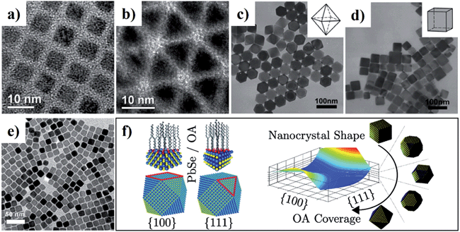 | ||
| Fig. 15 (a–e) TEM images of CS-NCs with different shapes: (a) cube-shaped CdSe NCs, (b) tetrahedron-shaped CdSe NCs, (c) octahedron-shaped PbS NCs, (d) cube-shaped PbS NCs, and (e) cube-shaped PbSe NCs. (f) Schematic diagram of the simulated shape evolution of PbSe NCs. The equilibrium shape is a function of the ligand surface coverage, which can be controlled by changing the concentration of OA during synthesis (reproduced with permission from ref. 80, copyright 2008, Wiley; ref. 138, copyright 2009, American Chemical Society; ref. 83, copyright 2011, Wiley; ref. 139, copyright 2012, American Chemical Society). | ||
In the case of lead chalcogenides, zinc-blende PbS NCs with various shapes and exposed facets were prepared by heating up a mixture of lead acetate and DDT in the presence of OA capping ligand.83 It was demonstrated that the amount of capping ligand was critical for the shape control of PbS NCs. As the amount of OA increased, the morphology of PbS NCs was tuned from octahedron to truncated octahedron, truncated cube, and cube.83 Fig. 15c and d show the TEM images of the octahedral- and cubic-shaped PbS NCs prepared with the aid of OA ligands. Similarly, cubic-shaped PbSe NCs were also synthesised using SeO2 as the selenide source in ODE in the presence of OA and TOP (Fig. 15e).80 The capping ligand OA was expected to bind with atoms on PbSe surfaces in the form of lead oleate. In the theoretical aspect, density functional theory (DFT) calculations were conducted to investigate the effect of the OA ligands on the facet determination of PbSe NCs.139 It was revealed that the different binding energies of OA on the {100} and {111} plane resulted in the different equilibrium ligand coverage on these facets, which determined final PbSe shapes. For uncapped PbSe nanocrystals, the {111} facet surface energy is higher than that of {100} facets. With OA ligands present at low concentration, the {111} surface is effectively passivated and its surface energy becomes much smaller than that of {100} surface, which leads to an octahedral shape. On the other hand, when the concentration of OA is increased, the {100} surface is well-passivated and has a lower surface energy, resulting in a cubic shape. The equilibrium shape-dependence on ligand coverage is illustrated in Fig. 15f.
For ternary metal chalcogenide compounds, tetrahedral chalcopyrite CuInSe2 NCs exposed with {111} facets were reported by Korgel et al. in 2009.116 In their work, CIS pyramids were prepared by heating metal chloride precursors in OLA solvent in the presence of selenourea (Fig. 16a).116 Recently, a general method has been developed for the controlled synthesis of ternary and quaternary copper chalcogenide nanocrystals (CuInS2, Cu2SnS3, and Cu2ZnSnS4). By heating up the precursor solution in octadecene at 220 °C, {111}-faceted tetrahedral nanocrystals with various sizes were obtained (Fig. 16b–d).140 Up to now, the synthesis of ternary and quaternary copper chalcogenide nanocrystals with thermodynamically stable {100} facets have not been reported by wet-chemical methods. This could be due to the fact that coordinating solvents or capping ligands are usually used for the synthesis, which reverse the growth rate along 〈100〉 and 〈111〉 directions in reaction solutions.
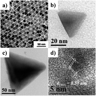 | ||
| Fig. 16 TEM images of tetrahedral nanocrystals: (a) chalcopyrite CuInSe2 NCs, (b) zinc-blende CuInS2 NCs, (c) zinc-blende Cu2SnS3 NCs, and (d) zinc-blende Cu2ZnSnS4 NCs (reproduced with permission from ref. 116, copyright 2009, American Chemical Society; and ref. 140, copyright 2013, Royal Society of Chemistry). | ||
As predicted by the crystalline structures illustrated in Fig. 14, the common crystal facets of wurtzite structure are {0001}, {10-10}, and {10-11} facets, which can generate various hexagonal shaped nanocrystals. For example, hexagonal wurtzite CuInSe2 NCs with predominantly {0001} facets were synthesised by injecting an oleylamine solution of InCl3 into another OLA solution containing copper–oleate and diphenyl diselenide at 225 °C.141 Wurtzite Cu2ZnSnS4 NCs with prism and plate shapes were selectively obtained by using different capping ligands (Fig. 17a and b). For the synthesis of prism CZTS NCs, a mixture of DDT and OLA was used as the solvent and ligands. When the solvent–ligand system was replaced by oleic acid only, CZTS nanoplates were obtained instead.142 Subsequently, well-defined hexagonal CZTS nanorods were reported by using the mixture of DDT and tert-dodecyl mercaptan (t-DDT) as the sulfur source.143 It was found that a combination of the two thiols is critical for the formation and assembly of nanorods. Fig. 17c and d show the HRTEM images of closely-packed and random distributed CZTS nanorods, respectively.
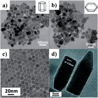 | ||
| Fig. 17 TEM images of wurtzite Cu2ZnSnS4 NCs with different shapes: (a) nanoprisms prepared in DDT and OLA, (b) nanoplates prepared in DDT and OA, (c) top-down HRTEM image of closely-packed CZTS nanorods, and (d) HRTEM image of the bullet-like CZTS nanorods (reproduced with permission from ref. 142, copyright 2011, Royal Society of Chemistry; ref. 143, copyright 2012, American Chemical Society). | ||
In addition to metal chalcogenides, wurtzite metal oxides such as zinc oxide have been a popular model system in the last few decades. ZnO has three crystalline structures: zinc-blende, wurtzite, and rock-salt. Among them, wurtzite structure is the most stable form at the ambient condition. Due to its unique crystal structure, wurtzite ZnO NCs tend to grow along the c-axis and form hexagonal rod- or wire-shaped morphologies, which are dominated with {10-10} facets. This is because the surface energy of non-polar {10-10} facet is lower than polar facets such as {0001} and {10-11}.144 Recently, the shape and thus the dominant facet of ZnO NCs were effectively controlled in identical reaction media by simply adjusting the reaction temperature, ligand concentration, and reaction times.145 Specifically, hexagonal ZnO nanorods dominated by {10-10} facets were prepared by injecting benzylamine into a hot solution of zinc acetate in benzylether at 210 °C (Fig. 18a and d). When benzylamine was injected into the same zinc precursor solution and heated at lower temperature (170 °C), ZnO nanocones dominated by {10-11} facets were obtained (Fig. 18b and e). If the mixture of zinc acetate, benzylamine, and benzylether was rapidly heated up to 220 °C and refluxed only for a short time, {0001}-faceted ZnO nanoplates were obtained (Fig. 18c and f). It was observed these nanoplates were actually formed in the initial stage of the cone-shaped samples. The control over these ZnO shapes was based on the aminolysis reaction between zinc acetate and benzylamine, and the tuning of ZnO surface energies by the passivation effect of benzylamine. One interesting discovery was that the {10-11}-dominated ZnO nanocones exhibited much higher reactivity for the photodegradation of Rhodamine B dye than other ZnO shapes. Similarly, these cone-shaped ZnO NCs also exhibited higher performance for the dye-sensitised solar cells (DSSCs) than the rod-shaped counterparts.144 This could be due to the unique surface chemistry of ZnO nanocones, which were exclusively terminated with oxygen atoms. In comparison with the ZnO nanorods exposed with Zn/O (50%/50%) atoms, the ZnO nanocone surfaces were terminated with 100% O atoms, resulting in the cone's effective passivation during the dye adsorption process (Fig. 19). First principle calculations for these adsorption systems also supported this proposal by comparing the binding energies of dyes on each ZnO facet.
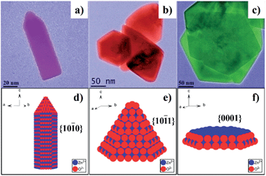 | ||
| Fig. 18 (a–c) TEM images of wurtzite ZnO NCs with different shapes: (a) rod-shaped, (b) cone-shaped, and (c) plate-shaped. (d–f) Schematic models and the dominant facets of ZnO NCs in (a–c), respectively (reproduced with permission from ref. 145, copyright 2012, Royal Society of Chemistry). | ||
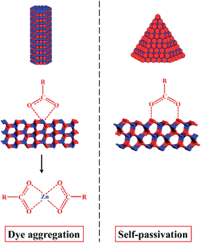 | ||
| Fig. 19 Comparison of the effect of ZnO surface termination on the dye adsorption for DSSCs. Left: the (10-10) surface of ZnO nanorods exposed with Zn/O (50%/50%) atoms is likely to be etched by acidic dye molecules, resulting in dye aggregation. Right: the (10-11) surface of ZnO nanocones is terminated with 100% O atoms, leading to a durable performance in DSSCs (reproduced with permission from ref. 144, copyright 2013, American Chemical Society). | ||
Another widely investigated metal oxide semiconductor is titanium oxide, a material which possesses three typical crystal structures: rutile, anatase, and brookite. Since the original work on {001}-faceted TiO2 single crystals in 2008,146 the facet-controlled synthesis of anatase TiO2 NCs have attracted considerable attention. In 2010, hierarchical anatase TiO2 spheres assembled from ultrathin nanosheets were prepared from titanium(IV) isopropoxide in the mixture of diethylenetriamine (DETA) and isopropanol.147 The exposed surfaces of those nanosheets were determined as {001} facets. It was proposed that the high-energy {001} facets were effectively capped by the DETA ligand, thus favoured the formation of sheet-shaped morphologies. Later on, pure micro-sized TiO2 nanosheets were synthesised by the solvothermal method using titanium tetrafluoride as the precursor and 1-butanol as the solvent.148 In 2012, uniform faceted TiO2 NCs with the size ranging from 10 to 100 nm were obtained in organic media.149 In this work, the percentage of particular facet was finely tuned. As shown in Fig. 20, TiO2 NCs with a variety of shapes ranging from plates to rods were controllably prepared by choosing the titanium precursors (TiCl4, TiF4, or the mixture) in either alcohol or amine solvents. In terms of individual facet surface-area-per-NC, it was explained that HF could be released from the TiF4 precursor during the reaction. The released fluoride ions, therefore, preferentially bind to the {001} facets, which leads to the higher exposure of {001} facets. The concentration of HF could be controlled through diluting the TiF4 precursor with TiCl4 and the choice of co-surfactant, which allowed the precise control on the percentage of {001} and {101} exposed facets.
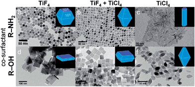 | ||
| Fig. 20 TEM images of TiO2 NCs synthesised using the precursor TiF4 (a and d), a mixed precursor of TiF4 and TiCl4 (b and e), and TiCl4 (c and f). The depicted in (a–c) and (d–f) are synthesised in the presence of OLA and 1-octadecanol (ODOL), respectively (reproduced with permission from ref. 149, copyright 2012, American Chemical Society). | ||
Other metal oxide NCs dominated with particular crystal facets have also been reported, but few of them were prepared in pure organic phase, which is due to the poor solubility or reactivity of the metal precursors in organic media. Therefore, there are a few examples of faceted metal oxides NCs, which are synthesised through the organic route but in the presence of trace amount of water. For example, the synthesis of In2O3 nanocubes were reported in 2006 by directly heating a slurry of indium(III) isopropoxide, oleic acid, oleylamine, and trioctylamine, with trace amounts of water at 90 °C.150 CeO2 nanocubes terminated with {200} facets were synthesised from cerium nitrate with the assistance of stabilizing agent oleic acid.151 The average size of CeO2 nanocubes were controlled by changing the concentration of cerium nitrate and the ratio of oleic acid/Ce(III). It was suggested that the cubic morphology was favoured by the oriented attachment of surfactant molecules on {200} planes, which reduced the overall surface energy of the system. Moreover, {111}-faceted WO3 octahedral NCs have been prepared from irregular-shaped commercial WO3 particles in absolute ethanol in the presence of HCl and urea.152
5. Phase-controlled synthesis of CS-NCs
As discussed above, the shape and therefore the exposed facet of CS-NCs are fundamentally determined by their crystal structures or phases, and can be selectively controlled by engineering the surface energy of a particular facet with the aid of capping ligands. As a basic parameter of crystal materials, the crystalline structure not only determines the intrinsic properties such as lattice parameters, atomic arrangements, and band structures, but also influences the growth behaviour of crystals, chemical stabilities and reactivity in environmental media. Therefore, controlling over the crystalline structures of semiconducting materials is equally important as other aspects, such as particle size, shape, and surface chemistry. Generally, a semiconductor usually has more than one stable crystal structure, such as the zinc-blende and wurtzite structures of PbS, or the rutile, anatase, and brookite structures of TiO2. For bulk semiconductors, they tend to crystallize into the thermodynamic stable structure at ambient conditions, and metastable structures can only be obtained at elevated temperature/pressure. In contrast, nano-sized semiconductor crystallites with various crystal structures can be obtained under mild conditions, which is due to the quantum size effect. This provides the possibility of tuning the electronic structure including band gap and Fermi level of these materials, which is quite attractive for various applications such as solar energy conversion.Over the past years, a number of strategies with proposed mechanisms have been reported for the phase-controlled synthesis of semiconductor NCs. For the solution-based synthetic approaches, it is generally accepted that the following reaction parameters, such as reaction temperature, doping elements, reactivity of precursors, the capping ligands, and the solvents have significant influence on the crystalline phase of nanocrystals. Beyond these factors, it is a challenge to reveal a general rule or mechanism which determines the final phase of those materials. This could be due to the diversity of material composition (especially in the case of ternary and quaternary compounds) and the large variety of reaction variables for each particular synthesis method. In 1999, Li et al. found the crystal structure of cadmium chalcogenide CdX (X = S, Se, Te) NCs was strongly influenced by the solvent and reaction temperature during the solvothermal process.35 The pure wurtzite CdS NCs were obtained from Cd power and elemental S in the presence of EDA, which was a strongly coordinating solvent. However, when EDA was replaced by diethylamine (DEA), the obtained CdS NCs crystallised with two phases: wurtzite phase and zinc-blende phase. It was suggested that both coordinating alkylamine solvents could react with Cd precursors to form intermediate complexes, which could be converted into CdS NCs at elevated temperatures. However, the stability constant of the complex formed in EDA was higher than the one formed in DEA, with the value of 10.09 and 2.50, respectively. In other words, those intermediate complexes possess different reactivity to form CdS NCs. The Cd-complex with high reactivity in EDA was likely to rapidly decompose into the dynamically-favoured wurtzite CdS NCs, while less reactive Cd-complex partially led to the formation of thermally-favoured zinc-blende CdS NCs. In 2003, the structure of Cd-complex was determined by the same group in the case wurtzite CdX NCs synthesised in EDA solvent. It was observed that a general CdX·0.5en (en = ethylenediamine) precursory phase was formed at a mild temperature, which decomposed to CdX NCs at a higher temperature. The CdSe·0.5en precursor possesses a three-dimensional (3D) layered structure, in which inorganic CdX slabs were interconnected by the bidentate EDA molecules (Fig. 21).153 It was found the way that Cd and Se atoms connected and their relative positions in the inorganic layers of CdSe·0.5en precursor were nearly the same as that of atomic slice cut from wurtzite CdSe crystal. Thus, it was reasonable to suggest that the transition from the inorganic–organic layered precursor to the final wurtzite structure is energy-favourable. Similarly, the effect of EDA solvent has also been observed for the synthesis of zinc chalcogenide NCs. Pure wurtzite zinc chalcogenide NCs were prepared by annealing the corresponding precursors (ZnS·0.5en, ZnSe·0.5en, and ZnSe·0.5en) at temperature above 350 °C.153,154 The crystal structure of these precursors were similar to those in the case of CdX NCs, which confirmed the proposed mechanism.
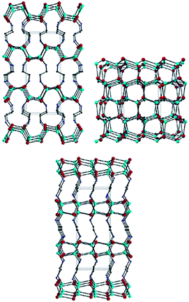 | ||
| Fig. 21 Structural view of CdSe·0.5en down the (b) (top, left), (c) (top, right) and (a) (bottom) axes of the orthorhombic cell. Red, cyan, blue, and black balls stand for Cd, Se, N, and C atoms, respectively. H atoms are omitted for clarity (reproduced with permission from ref. 153, copyright 2003, American Chemical Society). | ||
Similar rules have been observed by our group for the phase-controlled synthesis of ternary and quaternary copper chalcogenide NCs, such as CuInS2, Cu2SnS3, and Cu2ZnSnS4.140 Pure zinc-blende and wurtzite CuInS2 NCs were selectively obtained from the reaction between metal salt precursors and DDT in non-coordinating solvent ODE and coordinating solvent OLA, respectively. It was observed the intermediate of metal thiolate complex CuIn(SR)x was formed at the initial stage of reaction, which decomposed into final products as the reaction continued. X-ray diffraction (XRD) characterizations suggested that the crystallinity of the CuIn(SR)x complex was lower in ODE solvent compared to the complex formed in OLA, resulting in their different thermal stability (Fig. 22). Therefore, the less stable CuIn(SR)x complex in ODE was readily decomposed into the zinc-blende structure, while the highly stable precursor favoured the metastable wurtzite phase. The same effect of solvents was also observed in other copper chalcogenide NCs, including Cu2SnS3, and Cu2ZnSnS4. Further work is under way to investigate the crystal structure of the intermediate complexes formed in ODE and OLA solvents, which would reveal the critical mechanism behind the phase-controlled synthesis for copper chalcogenide NCs.
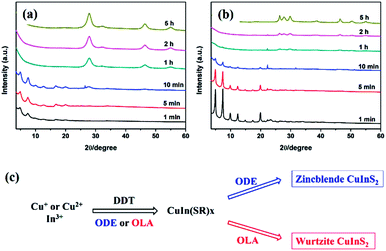 | ||
| Fig. 22 (a and b) XRD patterns of CuInS2 NCs prepared with different reaction times in ODE and OLA solvent, respectively. (c) Schematic diagram for the formation mechanism of CuInS2 NCs using different capping ligands (reproduced with permission from ref. 140, copyright 2013, Royal Society of Chemistry). | ||
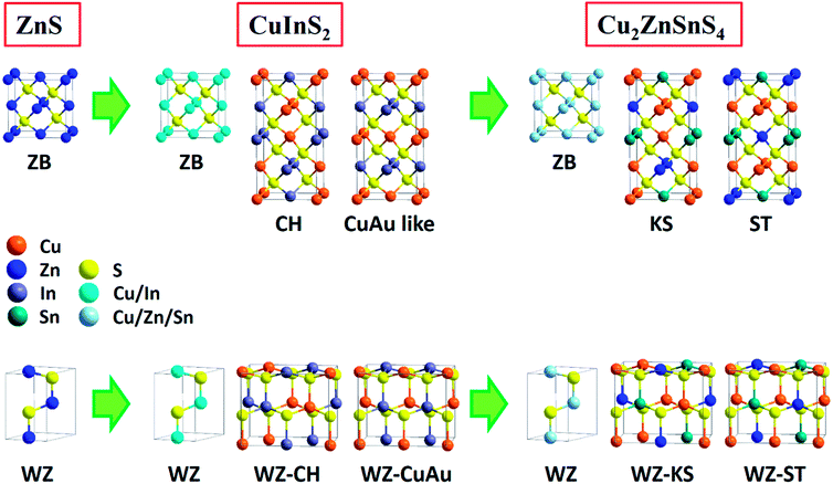
In fact, the composition and crystalline structure of ternary and quaternary copper chalcogenides are far more complicated than binary ones. As early as the 1950s, efforts had been made to predict the derivation and properties of metal chalcogenide semiconductors. It was known that ternary and quaternary compounds could be derived from binary ones by simply replacing one element with pairs from other groups of the periodic table while keeping the valence-electron/atom ratio constant.155,156 For example, ternary compound CuInS2 can be considered as substituting zinc ions in ZnS with copper and indium ions. Similar variants include CuGaS2, CuFeS2, CuSbS2, Cu2SnS3 and their selenide counterparts as long as the octet rule is obeyed. Similarly, generation of quaternary and pseudo-quaternary chalcogenide compounds can be considered as the further cation cross-substitution in ternary systems. While obeying the octet rule, a series of quaternary copper chalcogenides such as Cu2ZnSnS4, Cu2ZnGeS4, Cu2FeSnS4, Cu2CdSnS4, Cu2CoSnS4, CuIn1−xGaxS2, have also been reported.157–161 Fig. 23 illustrates the crystal structure derivation of ternary and quaternary copper chalcogenides (CuInS2 and Cu2ZnSnS4) from binary ZnS. Since ternary chalcogenides are derived from binary counterparts, they also share the basic crystalline structures, such as the zinc-blende (space group F43m) and wurtzite (space group P63mc) phases. In these two phases, metal cations of ternary and quaternary compounds can randomly occupy the corresponding positions of binary systems, leading to the metastable nature of these structures. The most stable phase of ternary and quaternary chalcogenides usually has precisely defined atomic positions for both metal and chalcogenide atoms. For example, at ambient conditions, the most stable phase of ternary CuInS2 is referred to as chalcopyrite (space group I42d) with each sulfur atom surrounded by two copper atoms and two indium atoms, which is the doubled structure of zinc-blende along c-axis. It was proposed that slight change of the atomic distribution in chalcopyrite would lead to a metastable CuAu-like structure, in which the copper layer and indium layer exist alternatively beside the sulfur layer. Likewise, another two metastable phases of CuInS2 can be derived from the wurtzite phase. They are orthorhombic structures and usually referred to as wurtzite–chalcopyrite and wurtzite–CuAu-like structures.162 Their primitive cells can be taken as a 2 × 2 × 1 supercell of a wurtzite unit cell, with the fractional atomic coordinates same with the ideal wurtzite structure before relaxation. For quaternary copper chalcogenide Cu2ZnSnS4, it also has six crystalline structures corresponding to those of ternary compounds, i.e. zinc-blende, kesterite, stannite, wurtzite, wurtzite–kesterite, and wurtzite–stannite structures. Bulk Cu2ZnSnS4 crystals favour the tetragonal kesterite structure (space group I![[4 with combining macron]](https://www.rsc.org/images/entities/char_0034_0304.gif) ), in which the CuZn and CuSn cation layers are alternately ordered in the direction of c-axis. Comparatively, the metastable stannite phase (space group I
), in which the CuZn and CuSn cation layers are alternately ordered in the direction of c-axis. Comparatively, the metastable stannite phase (space group I![[4 with combining macron]](https://www.rsc.org/images/entities/char_0034_0304.gif) 2m) possesses a different cation distribution, which comprises the alternative order of ZnSn and pure Cu layers. It should be noted that although zinc-blende and wurtzite structures can be clearly assigned based on their X-ray diffraction patterns, it is not always distinguishable with other derived structures with similar unit cells. For example, the powder X-ray diffraction pattern of kesterite is exactly the same as that of and stannite, and the difference between wurtzite and orthorhombic structure is negligible. Therefore, other techniques such as Raman scattering are often necessary for the precise characterization of ternary and quaternary chalcogenide compounds.
2m) possesses a different cation distribution, which comprises the alternative order of ZnSn and pure Cu layers. It should be noted that although zinc-blende and wurtzite structures can be clearly assigned based on their X-ray diffraction patterns, it is not always distinguishable with other derived structures with similar unit cells. For example, the powder X-ray diffraction pattern of kesterite is exactly the same as that of and stannite, and the difference between wurtzite and orthorhombic structure is negligible. Therefore, other techniques such as Raman scattering are often necessary for the precise characterization of ternary and quaternary chalcogenide compounds.
Reviewing preparation aspect again, the phase-controlled synthesis of CuInS2 NCs was originally reported in 2008 by Pan and coworkers.64 In their work, zinc-blende and wurtzite Cu–In–S ternary NCs with tunable compositions were prepared by the hot-injection method using copper and indium diethyl dithiocarbamate as metal precursors, OLA as activation agent, and OA or DDT as capping ligands. For the synthesis of zinc-blende phase, a mixture of Cu(dedc)2, In(dedc)3, OA, and ODE were heated to 200 °C, followed by the injection of OLA. In contrast, wurtzite phase samples were obtained by replacing OA with DDT as the capping ligand. It was suggested that CuInS2 NCs were formed by the dissolution of CuS, Cu2S, and In2S3 NCs and their subsequent reactions at high temperature. As shown in Fig. 24, CuS NCs were initially generated from Cu(dedc)2 in the presence of OLA, which reacted with In2S3 and formed CuInS2 with the structure of zinc-blende. Whereas, in the presence of DDT, Cu(dedc)2 was reduced to Cu2S NCs, resulting in the formation of CuInS2 NCs with the wurtzite structure. This mechanism was subsequently demonstrated by the direct observation of the phase transformation of biphasic Cu2S–CuInS2 to monophasic wurtzite CuInS2 nanocrystals.163,164 In 2009, Connor et al. reported the synthesis of wurtzite CuInS2 NCs from copper oleate and indium oleate in the presence of DDT and OLA.163 It was suggested that the generation of CuInS2 NCs started with Cu2S nanodisks followed by the epitaxial growth on one side of the nanodisks, resulting in the formation of biphasic Cu2S–CuInS2 NCs consisting of chalcocite Cu2S and wurtzite CuInS2. It was found this biphasic intermediate could be converted to monophasic wurtzite CuInS2 NCs at high temperatures, as shown in Fig. 25. Similar mechanism was also observed by Kolny-Olesiak and co-workers in 2010.164 In their method, Cu2S–CuInS2 hybrid nanostructures as well as pure wurtzite CuInS2 NCs were prepared by a hot-injection method from copper(I) acetate and indium(III) acetate in the presence of OLA, DDT and t-DDT. Recently, the relationship between the composition of binary system and the phase of ternary/quaternary compounds was further investigated in the case of CTS and CZTS NCs.165 It was revealed that CuS (or CuSe) preferred to form zinc-blende phase of CTS or CZTS nanocrystals, while Cu2S (or Cu2Se) favoured the wurtzite counterparts, which was in agreement with the initial finding by Pan et al.
 | ||
| Fig. 24 Schematic formation mechanism of CuInS2 NCs from Cu(dedc)2 and In(dedc)3 precursors in the presence of capping ligands (reproduced with permission from ref. 64, copyright 2008, American Chemical Society). | ||
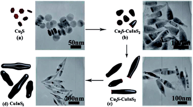 | ||
| Fig. 25 Schematic of the proposed growth mechanism with corresponding TEM images: (a) formation of Cu2S nanodisks at the initial stage, (b) epitaxial growth of CuInS2 on Cu2S nanodisks leads to biphasic NRs, (c) continued growth of CuInS2 with the conversion of Cu2S into CuInS2, and (d) monophasic CuInS2 NCs (reproduced with permission from ref. 163, copyright 2009, American Chemical Society). | ||
Although the phase control over metal chalcogenide NCs could be attributed to the formation of Cu2S or CuS NCs during the reaction, this mechanism is not always observed.140 A considerable number of investigations showed that the phase of CuInS2 NCs can also be controlled by the reaction temperature and the solvent–ligand, with zinc-blende and chalcopyrite structures being favoured by relatively high temperature and non-/weak-coordinating solvents. This is a consequence of the thermodynamic stability of the intermediate complexes determining the crystal structure of final CuInS2 products. In 2009, the effects of reaction temperature and capping ligand were investigated for the synthesis of CuInS2 NCs using a single-source precursor (Ph3P)CuIn(SC{O}Ph)4 in the presence of TOPO and DDT.166 It was reported that when the ratio of TOPO and DDT was 50/50, wurtzite phase CuInS2 could be obtained at temperature below 275 °C, while zinc-blende phase was obtained above this temperature (Fig. 26). However, when the ratio of TOPO and DDT was increased to 75/25, only wurtzite CuInS2 NCs were obtained regardless of the reaction temperature. These results clearly show the significant roles of reaction temperature and capping ligands for the phase determination of CuInS2 NC. Meanwhile, phase-controlled CuInS2 nanoparticles were also prepared by Nose et al. involving simple heating in organic solvents.167 Copper and indium precursor solutions were separately prepared by dissolving CuI and InCl3 in a mixed solvent containing TOP and ODE. The sulfur source was prepared by dissolving elemental sulfur in TOP. Then the copper source, indium source, sulfur source, and surfactant (OLA or HDA) were mixed together as the starting solution. Chalcopyrite or zinc-blende phase CuInS2 NCs were obtained by heating up the starting solution immediately after the addition of surfactant amine. On the other hand, if the starting solution was stirred at room temperature for 3 h before heat-up, wurtzite phase CuInS2 was obtained. It was suggested the phase selectivity was determined by the growth rate of CuInS2 NCs. In the former case, metallic monomers were coordinated with TOP, forming highly reactive precursors, which leads to the fast nucleation and the formation of thermodynamically stable CuInS2 with the zinc-blende phase. In the case of delayed reaction, metallic monomers were coordinated with amine, forming more stable precursors, which were less reactive. Therefore, the nucleation was relative slow and favoured the formation of kinetically stable CuInS2 with the wurtzite phase. In short, the phase determination of CuInS2 NCs was closely related to the reaction temperature, precursor reactivity, and solvent–ligands.
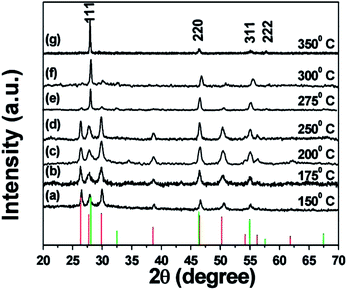 | ||
Fig. 26 XRD patterns of CuInS2 NCs synthesised at different temperatures for TOPO![[thin space (1/6-em)]](https://www.rsc.org/images/entities/char_2009.gif) : :![[thin space (1/6-em)]](https://www.rsc.org/images/entities/char_2009.gif) DDT = 50 DDT = 50![[thin space (1/6-em)]](https://www.rsc.org/images/entities/char_2009.gif) : :![[thin space (1/6-em)]](https://www.rsc.org/images/entities/char_2009.gif) 50. The red and green lines at the bottom refer to the peak positions of wurtzite and zinc-blende phases, respectively (reproduced with permission from ref. 166, copyright 2009, American Chemical Society). 50. The red and green lines at the bottom refer to the peak positions of wurtzite and zinc-blende phases, respectively (reproduced with permission from ref. 166, copyright 2009, American Chemical Society). | ||
Similar solution-based approaches were also applied to the synthesis of quaternary and quasi-quaternary copper chalcogenides NCs, such as Cu2ZnSnS(Se)4,34,66–68,142,143,168,169 Cu2ZnGeS(Se)4,161 Cu2MSnS4 (M = Co, Cd, Mn, Fe),157–160 and CuInGaS(Se)2,170 etc. In 2009, the synthesis of kesterite Cu2ZnSnS4 NCs was simultaneously reported by several research groups. Hillhouse et al. prepared Cu2ZnSnS4 NCs through a hot-injection method, i.e. injecting a sulfur precursor into the hot solution containing metal precursors and OLA.66 They also applied similar method to synthesise CuInGaS2 NCs from copper, indium, gallium chlorides and sulfur in OLA solvent.170 Meanwhile, Prieto and coworkers reported the synthesis of Cu2ZnSnS4 NCs by injecting sulfur and metal precursors into a hot solvent of TOPO.67 In 2011, Cu2ZnSnS4 NCs with the wurtzite structure were prepared by a hot injection method by Li and coworkers.142 They injected the DDT solution of metal precursors into a hot mixture containing OLA, OA, and DDT at 240 °C. In 2012, Cu2ZnSnS4 NCs with the metastable orthorhombic phase (space group Pmn21) were reported, which was derived from hexagonal wurtzite phase.168 In this work, metal precursors and the sulfur source (thiocarbamide) were dissolved in a mixed solvent of water and EDA, followed by heating to 200 °C in autoclaves. Alternatively, Cu2ZnSnS4 NCs could also be prepared by a non-injection method. For example, the synthesis of kesterite Cu2ZnSnS4 NCs was reported by Korgel et al. in 2009, in which metal precursors and sulfur were simply mixed in OLA at room temperature, followed by heating up to 280 °C.68 In 2012, wurtzite Cu2ZnSnS4 NCs were synthesised by heating up a mixture of metal dithiocarbamate, hexadecenethiol, and trioctylamine.34 High quality self-assembled Cu2ZnSnS4 nanorods with the wurtzite phase were also obtained by using a mixed solution of DDT and t-DDT as the sulfur source.143
The phase-controlled synthesis of CZTS NCs and the mechanism investigation were only investigated recently. In 2013, a general method was developed in our group for the synthesis of zinc-blende and wurtzite copper chalcogenide NCs using DDT as the sulfur source.140 It was observed that zinc-blende CZTS NCs were favoured in non-coordinating solvents such as ODE, while wurtzite phase products were favoured in coordinating solvents such as OLA. This could be attributed to the different coordination strength between solvents and metal precursors, thus affected the stability and reactivity of intermediate complexes. This proposal was in agreement with a recent study reported by Jiang et al.171 They controlled the kesterite and wurtzite phases of CZTS in hot organic solvents and revealed that reaction between zinc and sulfur precursors is the key to the phase-controlled synthesis of CZTS NCs. Sulfur source solution was initially prepared by dissolving elemental sulfur in ODE solvent at 155 °C. The colour of the ODE-S solution changed from yellow to orange as the heating process continued. Kesterite and wurtzite CZTS NCs were obtained when the yellow and orange ODE-S precursors were injected into the hot solution of metal acetate, OA, and DDT, respectively (Fig. 27). It was proposed that organic polysulfides (RSxR) was formed when elemental sulfur (S8) reacted with ODE solvent, where x was smaller in the yellow ODE-S than the orange one. In other word, the orange ODE-S solution contained polysulfides with long S chains compared to the yellow ODE-S solution, resulting in its higher reactivity during reaction. They concluded that a low-reactivity sulfur source favoured kesterite CZTS, while high-reactivity one favoured wurtzite CZTS. It was further observed that only the kesterite CZTS NCs were obtained if the zinc precursor was changed from zinc acetate to zinc chloride. This was mainly due to the relative low reactivity of zinc chloride, in agreement with previous observation that less reactive sulfur precursor lead to kesterite phase. Therefore, it could be concluded that a faster reaction between Zn and S precursors favoured the formation of wurtzite phase CZTS NCs, while slower reaction favoured the kesterite one, as illustrated in Fig. 28.
 | ||
| Fig. 27 CZTS NCs with kesterite and wurtzite structures were synthesised from metal acetate salts with either yellow or orange colour ODE-S as the sulfur precursor (reproduced with permission from ref. 171, copyright 2013, American Chemical Society). | ||
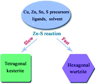 | ||
| Fig. 28 Schematic diagram of the proposed mechanism of phase-controlled synthesis of Cu2ZnSnS4 NCs. The crystalline phase was determined by the reactivity between Zn and S, where a preference for Zn–S reaction over Sn–S reaction favours the formation of a metastable hexagonal wurtzite structure (reproduced with permission from ref. 171, copyright 2013, American Chemical Society). | ||
As can be seen from above summary, several mechanisms (such as the binary chalcogenide determined, intermediate stability determined, and the precursor reactivity determined) have been proposed for the phase selectivity of copper chalcogenide NCs. However, they might not be all the possible mechanisms for the growth of CS-NCs, because the synthetic method and phase-controlled mechanisms are under development. One hint can be found from a recent development of the phase control over the binary chalcogenide NCs. It was first time observed that the phase of CdX NCs was highly dependent on their surface chemistry.172 Seed NCs with wurtzite and zinc-blende structures were separately prepared by a hot-injection method in the presence of appropriate ligands and solvents. Subsequently, they were covered by monolayer of either cation or anion through the SILAR method, followed by annealing at 240 °C. It was found pure wurtzite CdX NCs were obtained if the surfaces of seed NCs were cation-rich, no matter whether the seed samples were wurtzite or zinc-blende. In contrast, if the surfaces of seed NCs were anion-rich, only zinc-blende NCs could be obtained, as shown in Fig. 29. It was also demonstrated that this effect was only contributed by ions on the surface of NCs, not the excess ions in the solution. The reason for the phase selectivity was the nature of the surface, which influenced the surface energy and thus the phase stability. Due to the similar properties of chalcogenide compounds, it is reasonable to propose that these results could also be further explored for the phase control of other metal chalcogenide NCs, and there are still a long way for the deeper understanding of phase-controlled synthesis of CS-NCs.
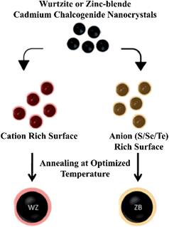 | ||
| Fig. 29 Schematic illustration for the phase transformation of cadmium chalcogenide NCs through the surface chemistry engineering (reproduced with permission from ref. 172, copyright 2013, Royal Society of Chemistry). | ||
6. Conclusions and outlook
Due to their attractive optoelectronic properties, semiconductor nanocrystals, especially metal oxide and metal chalcogenide NCs are considered promising candidates in a variety of applications, such as photocatalysis, light emitting diode, biolabelling, solar energy conversion, etc. To achieve high performance in these applications, the controlled synthesis of high quality semiconductor nanocrystals with tunable physical and chemical properties is the key factor. Among synthetic methods, organic solvent mediated approaches provide a wide range of opportunities to finely control the geometrical and structural properties of nanocrystals, combined with the benefits of low cost, low temperature, and feasible large-area solution processing. The present review summarised the general strategies and latest development of the controlled synthesis of popular metal oxides/chalcogenides in terms of their sizes, facets, phases, and the surface chemistry. Although tremendous achievements on synthetic methods and techniques have been obtained, the field of controlled-synthesis of nanocrystals is still under development with some challenges and opportunities to be met.Firstly, in terms of the size control and surface chemistry of semiconductor nanocrystals (especially quantum dots), the large scale synthesis of products with focused size distribution is still a challenge. This requires further exploration of the synthetic routes and techniques suitable for scalable synthesis. The particle growth mechanism is also essential to semiconductor nanocrystal fabrications, especially for ternary and quaternary nanocrystals as these are much more complicated and emerging as promising candidates in various applications. Besides, current nanocrystal research mainly focus on quantum-sized (2–10 nm) samples, but less on sub-nanosized species due to the difficulty in identification. Since the metastable sub-nanosized clusters are of particular importance in understanding the growth of nanocrystals, it is suggested that more opportunities exist in this area. In addition, although various strategies have been applied to the surface passivation of nanocrystals, there are still some unknowns such as the true effect or working mechanism of passivating species.
Secondly, faceted metal chalcogenides/oxide nanocrystals have been prepared by solution approaches in the presence of organic ligands and solvents. However, the mechanisms and growth behaviour have hardly been investigated systematically. The control over the percentage of particular facets and the wide range of size control (from nanosized to microsized) are also the challenges at present. Another challenge comes from the in situ growth of faceted nanocrystals on substrate materials. To date, only limited examples, such as ZnO nanowire arrays have been reported on faceted nanocrystals grown on substrates, which are exposed with low energy {10-10} facets. It is predicted that advanced properties and device performances will be achieved if assembles with high reactive facets are created.
Thirdly, a deeper understanding of the phase control of semiconductor nanocrystals, especially metal chalcogenide nanocrystals is still needed. It has been shown that the phase of metal chalcogenides is strongly dependent on the choice of ligands and solvents, reactant precursors, and reaction temperatures, etc. However, there is still a lack of universal strategy and mechanism for the phase-controlled synthesis of various materials ranging from binary to quaternary compounds.
Finally, the last decades have seen evolutions in various scientific fields, which are often accompanied with the development of novel materials. Therefore, the approaches and understandings already made for current materials should serve as guidelines to explore undiscovered analogous nanocrystals with desirable properties. To achieve this goal, a deeper partnership between theoretical prediction and experimental observation is required, as well as close cooperation with interdisciplinary perspectives.
Notes and references
- L. E. Brus, J. Chem. Phys., 1983, 79, 5566–5571 CrossRef CAS PubMed.
- L. Brus, J. Chem. Phys., 1986, 90, 2555–2560 CrossRef CAS.
- M. G. Bawendi, M. L. Steigerwald and L. E. Brus, Annu. Rev. Phys. Chem., 1990, 41, 477–496 CrossRef CAS.
- M. L. Steigerwald and L. E. Brus, Acc. Chem. Res., 1990, 23, 183–188 CrossRef CAS.
- D. J. Norris and M. G. Bawendi, Phys. Rev. B: Condens. Matter Mater. Phys., 1996, 53, 16338–16346 CrossRef CAS.
- J. Y. Kim, O. Voznyy, D. Zhitomirsky and E. H. Sargent, Adv. Mater., 2013, 25, 4986–5010 CrossRef CAS PubMed.
- Y. Xia, P. Yang, Y. Sun, Y. Wu, B. Mayers, B. Gates, Y. Yin, F. Kim and H. Yan, Adv. Mater., 2003, 15, 353–389 CrossRef CAS.
- D. Koziej, A. Lauria and M. Niederberger, Adv. Mater., 2014, 26, 235–257 CrossRef CAS PubMed.
- M.-R. Gao, Y.-F. Xu, J. Jiang and S.-H. Yu, Chem. Soc. Rev., 2013, 42, 2986–3017 RSC.
- A. Urbieta, P. Fernández and J. Piqueras, J. Appl. Phys., 2004, 96, 2210–2213 CrossRef CAS PubMed.
- J. J. Wu and S. C. Liu, Adv. Mater., 2002, 14, 215–218 CrossRef CAS.
- X. Xing, K. Zheng, H. Xu, F. Fang, H. Shen, J. Zhang, J. Zhu, C. Ye, G. Cao, D. Sun and G. Chen, Micron, 2006, 37, 370–373 CrossRef CAS PubMed.
- G. A. Ozin, M. R. Steele and A. J. Holmes, Chem. Mater., 1994, 6, 999–1010 CrossRef.
- S. H. Xin, P. D. Wang, A. Yin, C. Kim, M. Dobrowolska, J. L. Merz and J. K. Furdyna, Appl. Phys. Lett., 1996, 69, 3884–3886 CrossRef CAS PubMed.
- S. V. Ivanov, A. A. Toropov, S. V. Sorokin, T. V. Shubina, I. V. Sedova, A. A. Sitnikova, P. S. Kop'ev, Z. I. Alferov, H.-J. Lugauer, G. Reuscher, M. Keim, F. Fischer, A. Waag and G. Landwehr, Appl. Phys. Lett., 1999, 74, 498–500 CrossRef CAS PubMed.
- J. J. Berry, S. H. Chun, K. C. Ku, N. Samarth, I. Malajovich and D. D. Awschalom, Appl. Phys. Lett., 2000, 77, 3812–3814 CrossRef CAS PubMed.
- Y. Jouane, S. Colis, G. Schmerber, P. Kern, A. Dinia, T. Heiser and Y. A. Chapuis, J. Mater. Chem., 2011, 21, 1953–1958 RSC.
- H. Usui, Y. Shimizu, T. Sasaki and N. Koshizaki, J. Phys. Chem. B, 2004, 109, 120–124 CrossRef PubMed.
- D. B. Mitzi, Adv. Mater., 2009, 21, 3141–3158 CrossRef CAS.
- D. B. Mitzi, O. Gunawan, T. K. Todorov, K. Wang and S. Guha, Sol. Energy Mater. Sol. Cells, 2011, 95, 1421–1436 CrossRef CAS PubMed.
- L. E. Brus, J. Chem. Phys., 1984, 80, 4403–4409 CrossRef CAS PubMed.
- L. Spanhel, M. Haase, H. Weller and A. Henglein, J. Am. Chem. Soc., 1987, 109, 5649–5655 CrossRef CAS.
- M.-M. Titirici, M. Antonietti and A. Thomas, Chem. Mater., 2006, 18, 3808–3812 CrossRef CAS.
- D. L. Morgan, H.-Y. Zhu, R. L. Frost and E. R. Waclawik, Chem. Mater., 2008, 20, 3800–3802 CrossRef CAS.
- A. Mamakhel, C. Tyrsted, E. D. Bøjesen, P. Hald and B. B. Iversen, Cryst. Growth Des., 2013, 13, 4730–4734 CAS.
- Z. Zhuang, Q. Peng and Y. Li, Chem. Soc. Rev., 2011, 40, 5492–5513 RSC.
- Y. Yin and A. P. Alivisatos, Nature, 2005, 437, 664–670 CrossRef CAS PubMed.
- Z. Zhang, M. Lu, H. Xu and W.-S. Chin, Chem.–Eur. J., 2007, 13, 632–638 CrossRef CAS PubMed.
- S. Mourdikoudis and L. M. Liz-Marzán, Chem. Mater., 2013, 25, 1465–1476 CrossRef CAS.
- E. A. Weiss, Acc. Chem. Res., 2013, 46, 2607–2615 CrossRef CAS PubMed.
- C. B. Murray, D. J. Norris and M. G. Bawendi, J. Am. Chem. Soc., 1993, 115, 8706–8715 CrossRef CAS.
- W. Zhang, H. Zhang, Y. Feng and X. Zhong, ACS Nano, 2012, 6, 11066–11073 CAS.
- H. Zhong, S. S. Lo, T. Mirkovic, Y. Li, Y. Ding, Y. Li and G. D. Scholes, ACS Nano, 2010, 4, 5253–5262 CrossRef CAS PubMed.
- M. D. Regulacio, C. Ye, S. H. Lim, M. Bosman, E. Ye, S. Chen, Q.-H. Xu and M.-Y. Han, Chem.–Eur. J., 2012, 18, 3127–3131 CrossRef CAS PubMed.
- Y. Li, H. Liao, Y. Ding, Y. Fan, Y. Zhang and Y. Qian, Inorg. Chem., 1999, 38, 1382–1387 CrossRef CAS.
- J. Xu, J.-P. Ge and Y.-D. Li, J. Phys. Chem. B, 2006, 110, 2497–2501 CrossRef CAS PubMed.
- H. G. Yang, G. Liu, S. Z. Qiao, C. H. Sun, Y. G. Jin, S. C. Smith, J. Zou, H. M. Cheng and G. Q. Lu, J. Am. Chem. Soc., 2009, 131, 4078–4083 CrossRef CAS PubMed.
- X. Wang, J. Zhuang, Q. Peng and Y. D. Li, Nature, 2005, 437, 121–124 CrossRef CAS PubMed.
- X. Wang, Q. Peng and Y. Li, Acc. Chem. Res., 2007, 40, 635–643 CrossRef CAS PubMed.
- D. Pan, Q. Wang and L. An, J. Mater. Chem., 2009, 19, 1063–1073 RSC.
- Q. Wang, D. Pan, S. Jiang, X. Ji, L. An and B. Jiang, Chem.–Eur. J., 2005, 11, 3843–3848 CrossRef CAS PubMed.
- V. Lesnyak, N. Gaponik and A. Eychmuller, Chem. Soc. Rev., 2013, 42, 2905–2929 RSC.
- D. Aldakov, A. Lefrancois and P. Reiss, J. Mater. Chem. C, 2013, 1, 3756–3776 RSC.
- P. Samokhvalov, M. Artemyev and I. Nabiev, Chem.–Eur. J., 2013, 19, 1534–1546 CrossRef CAS PubMed.
- J. Kolny-Olesiak and H. Weller, ACS Appl. Mater. Interfaces, 2013, 5, 12221–12237 CAS.
- J. Lee, S. Zhang and S. Sun, Chem. Mater., 2013, 25, 1293–1304 CrossRef CAS.
- G. Liu, J. C. Yu, G. Q. Lu and H.-M. Cheng, Chem. Commun., 2011, 47, 6763–6783 RSC.
- T.-D. Nguyen and T.-O. Do, Size- and Shape-Controlled Synthesis of Monodisperse Metal Oxide and Mixed Oxide Nanocrystals, in Nanocrystal, ed. Y. Masuda, InTech, 2011, vol. 2, pp. 55–85 Search PubMed.
- V. K. LaMer and R. H. Dinegar, J. Am. Chem. Soc., 1950, 72, 4847–4854 CrossRef CAS.
- T. Sugimoto, Adv. Colloid Interface Sci., 1987, 28, 65–108 CrossRef CAS.
- A. Fick, Ann Phys., 1855, 170, 59–86 CrossRef.
- X. Peng, J. Wickham and A. P. Alivisatos, J. Am. Chem. Soc., 1998, 120, 5343–5344 CrossRef CAS.
- X. Peng and J. Thessing, Controlled Synthesis of High Quality Semiconductor Nanocrystals, in Semiconductor Nanocrystals and Silicate Nanoparticles, ed. X. Peng and D. M. P. Mingos, Springer, Berlin, Heidelberg, 2005, vol. 118, pp. 79–119 Search PubMed.
- Z. A. Peng and X. Peng, J. Am. Chem. Soc., 2001, 123, 183–184 CrossRef CAS.
- L. Qu, Z. A. Peng and X. Peng, Nano Lett., 2001, 1, 333–337 CrossRef CAS.
- C. B. Murray, C. R. Kagan and M. G. Bawendi, Annu. Rev. Mater. Sci., 2000, 30, 545–610 CrossRef CAS.
- C. B. Murray, S. Sun, W. Gaschler, H. Doyle, T. A. Betley and C. R. Kagan, IBM J. Res. & Dev., 2001, 45, 47–56 CrossRef CAS.
- M. A. Hines and G. D. Scholes, Adv. Mater., 2003, 15, 1844–1849 CrossRef CAS.
- W. W. Yu, J. C. Falkner, B. S. Shih and V. L. Colvin, Chem. Mater., 2004, 16, 3318–3322 CrossRef CAS.
- K. A. Abel, J. Shan, J.-C. Boyer, F. Harris and F. C. J. M. van Veggel, Chem. Mater., 2008, 20, 3794–3796 CrossRef CAS.
- P. M. Allen and M. G. Bawendi, J. Am. Chem. Soc., 2008, 130, 9240–9241 CrossRef CAS PubMed.
- Q. Guo, S. J. Kim, M. Kar, W. N. Shafarman, R. W. Birkmire, E. A. Stach, R. Agrawal and H. W. Hillhouse, Nano Lett., 2008, 8, 2982–2987 CrossRef CAS PubMed.
- W. Han, L. Yi, N. Zhao, A. Tang, M. Gao and Z. Tang, J. Am. Chem. Soc., 2008, 130, 13152–13161 CrossRef CAS PubMed.
- D. Pan, L. An, Z. Sun, W. Hou, Y. Yang, Z. Yang and Y. Lu, J. Am. Chem. Soc., 2008, 130, 5620–5621 CrossRef CAS PubMed.
- M. G. Panthani, V. Akhavan, B. Goodfellow, J. P. Schmidtke, L. Dunn, A. Dodabalapur, P. F. Barbara and B. A. Korgel, J. Am. Chem. Soc., 2008, 130, 16770–16777 CrossRef CAS PubMed.
- Q. Guo, H. W. Hillhouse and R. Agrawal, J. Am. Chem. Soc., 2009, 131, 11672–11673 CrossRef CAS PubMed.
- S. C. Riha, B. A. Parkinson and A. L. Prieto, J. Am. Chem. Soc., 2009, 131, 12054–12055 CrossRef CAS PubMed.
- C. Steinhagen, M. G. Panthani, V. Akhavan, B. Goodfellow, B. Koo and B. A. Korgel, J. Am. Chem. Soc., 2009, 131, 12554–12555 CrossRef CAS PubMed.
- A. Khare, A. W. Wills, L. M. Ammerman, D. J. Norris and E. S. Aydil, Chem. Commun., 2011, 47, 11721–11723 RSC.
- H. Nishi, T. Nagano, S. Kuwabata and T. Torimoto, Phys. Chem. Chem. Phys., 2014, 16, 672–675 RSC.
- T. J. Trentler, T. E. Denler, J. F. Bertone, A. Agrawal and V. L. Colvin, J. Am. Chem. Soc., 1999, 121, 1613–1614 CrossRef CAS.
- J. Chang and E. R. Waclawik, J. Nanopart. Res., 2012, 14, 1012 CrossRef.
- E. Hao, N. A. Anderson, J. B. Asbury and T. Lian, J. Phys. Chem. B, 2002, 106, 10191–10198 CrossRef CAS.
- R. Si, Y.-W. Zhang, L.-P. You and C.-H. Yan, Angew. Chem., Int. Ed., 2005, 44, 3256–3260 CrossRef CAS PubMed.
- K. Manthiram and A. P. Alivisatos, J. Am. Chem. Soc., 2012, 134, 3995–3998 CrossRef CAS PubMed.
- M. Niederberger and N. Pinna, Metal Oxide Nanoparticles in Organic Solvents, Springer, UK, 2009 Search PubMed.
- M. Niederberger and M. Antonietti, Nonaqueous Sol–Gel Routes to Nanocrystalline Metal Oxides, in Nanomaterials Chemistry, Wiley-VCH Verlag GmbH & Co. KGaA, 2007, vol. 3, pp. 119–137 Search PubMed.
- N. Pinna and M. Niederberger, Angew. Chem., Int. Ed., 2008, 47, 5292–5304 CrossRef CAS PubMed.
- Y. A. Yang, H. Wu, K. R. Williams and Y. C. Cao, Angew. Chem., Int. Ed., 2005, 44, 6712–6715 CrossRef CAS PubMed.
- O. Chen, X. Chen, Y. Yang, J. Lynch, H. Wu, J. Zhuang and Y. C. Cao, Angew. Chem., Int. Ed., 2008, 47, 8638–8641 CrossRef CAS PubMed.
- T.-Y. Liu, M. Li, J. Ouyang, M. B. Zaman, R. Wang, X. Wu, C.-S. Yeh, Q. Lin, B. Yang and K. Yu, J. Phys. Chem. C, 2009, 113, 2301–2308 CAS.
- Y. Wang, X. Yang, G. Xiao, B. Zhou, B. Liu, G. Zou and B. Zou, CrystEngComm, 2013, 15, 5496–5505 RSC.
- Z. Zhuang, X. Lu, Q. Peng and Y. Li, Chem.–Eur. J., 2011, 17, 10445–10452 CrossRef CAS PubMed.
- H. Shen, J. Z. Niu, H. Wang, X. Li, L. S. Li and X. Chen, Dalton Trans., 2010, 39, 11432–11438 RSC.
- P. D. Cozzoli, M. L. Curri, A. Agostiano, G. Leo and M. Lomascolo, J. Phys. Chem. B, 2003, 107, 4756–4762 CrossRef CAS.
- M. Monge, M. L. Kahn, A. Maisonnat and B. Chaudret, Angew. Chem., Int. Ed., 2003, 42, 5321–5324 CrossRef CAS PubMed.
- M. Yin, Y. Gu, I. L. Kuskovsky, T. Andelman, Y. Zhu, G. F. Neumark and S. O'Brien, J. Am. Ceram. Soc., 2004, 126, 6206–6207 CrossRef CAS PubMed.
- N. S. Norberg and D. R. Gamelin, J. Phys. Chem. B, 2005, 109, 20810–20816 CrossRef CAS PubMed.
- J. D. Levine and P. Mark, Phys. Rev., 1966, 144, 751–763 CrossRef CAS.
- M. Sykora, A. Y. Koposov, J. A. McGuire, R. K. Schulze, O. Tretiak, J. M. Pietryga and V. I. Klimov, ACS Nano, 2010, 4, 2021–2034 CrossRef CAS PubMed.
- J. E. Murphy, M. C. Beard, A. G. Norman, S. P. Ahrenkiel, J. C. Johnson, P. Yu, O. I. Mićić, R. J. Ellingson and A. J. Nozik, J. Am. Chem. Soc., 2006, 128, 3241–3247 CrossRef CAS PubMed.
- J. T. Stewart, L. A. Padilha, M. M. Qazilbash, J. M. Pietryga, A. G. Midgett, J. M. Luther, M. C. Beard, A. J. Nozik and V. I. Klimov, Nano Lett., 2011, 12, 622–628 CrossRef PubMed.
- M. A. Hines and P. Guyot-Sionnest, J. Phys. Chem., 1996, 100, 468–471 CrossRef CAS.
- B. O. Dabbousi, J. Rodriguez-Viejo, F. V. Mikulec, J. R. Heine, H. Mattoussi, R. Ober, K. F. Jensen and M. G. Bawendi, J. Phys. Chem. B, 1997, 101, 9463–9475 CrossRef CAS.
- J. J. Li, Y. A. Wang, W. Guo, J. C. Keay, T. D. Mishima, M. B. Johnson and X. Peng, J. Am. Chem. Soc., 2003, 125, 12567–12575 CrossRef CAS PubMed.
- D. Chen, F. Zhao, H. Qi, M. Rutherford and X. Peng, Chem. Mater., 2010, 22, 1437–1444 CrossRef CAS.
- W. Nan, Y. Niu, H. Qin, F. Cui, Y. Yang, R. Lai, W. Lin and X. Peng, J. Am. Chem. Soc., 2012, 134, 19685–19693 CrossRef CAS PubMed.
- P. Yang, M. Ando, T. Taguchi and N. Murase, J. Phys. Chem. C, 2011, 115, 14455–14460 CAS.
- N. Duxin, F. Liu, H. Vali and A. Eisenberg, J. Am. Chem. Soc., 2005, 127, 10063–10069 CrossRef CAS PubMed.
- M. Wang, J. K. Oh, T. E. Dykstra, X. Lou, G. D. Scholes and M. A. Winnik, Macromolecules, 2006, 39, 3664–3672 CrossRef CAS.
- S. Vempati, Y. Ertas and T. Uyar, J. Phys. Chem. C, 2013, 117, 21609–21618 CAS.
- H.-L. Chou, C.-H. Tseng, K. C. Pillai, B.-J. Hwang and L.-Y. Chen, J. Phys. Chem. C, 2011, 115, 20856–20863 CAS.
- T. Dannhauser, M. O'Neil, K. Johansson, D. Whitten and G. McLendon, J. Phys. Chem., 1986, 90, 6074–6076 CrossRef CAS.
- P. Szymanski, N. Fuke, A. Y. Koposov, V. W. Manner, L. B. Hoch and M. Sykora, Chem. Commun., 2011, 47, 6437–6439 RSC.
- P. Thangadurai, S. Balaji and P. T. Manoharan, Nanotechnology, 2008, 19, 435708 CrossRef CAS PubMed.
- D. V. Talapin, A. L. Rogach, A. Kornowski, M. Haase and H. Weller, Nano Lett., 2001, 1, 207–211 CrossRef CAS.
- D. V. Talapin and C. B. Murray, Science, 2005, 310, 86–89 CrossRef CAS PubMed.
- S. Guo, D. Bao, S. Upadhyayula, W. Wang, A. B. Guvenc, J. R. Kyle, H. Hosseinibay, K. N. Bozhilov, V. I. Vullev, C. S. Ozkan and M. Ozkan, Adv. Funct. Mater., 2013, 23, 5199–5211 CrossRef CAS.
- M.-Q. Dai and L.-Y. L. Yung, Chem. Mater., 2013, 25, 2193–2201 CrossRef CAS.
- E. J. D. Klem, H. Shukla, S. Hinds, D. D. MacNeil, L. Levina and E. H. Sargent, Appl. Phys. Lett., 2008, 92, 212105 CrossRef PubMed.
- J. M. Luther, M. Law, M. C. Beard, Q. Song, M. O. Reese, R. J. Ellingson and A. J. Nozik, Nano Lett., 2008, 8, 3488–3492 CrossRef CAS PubMed.
- A. G. Pattantyus-Abraham, I. J. Kramer, A. R. Barkhouse, X. Wang, G. Konstantatos, R. Debnath, L. Levina, I. Raabe, M. K. Nazeeruddin, M. Grätzel and E. H. Sargent, ACS Nano, 2010, 4, 3374–3380 CrossRef CAS PubMed.
- J. M. Luther, M. Law, Q. Song, C. L. Perkins, M. C. Beard and A. J. Nozik, ACS Nano, 2008, 2, 271–280 CrossRef CAS PubMed.
- J. Aldana, Y. A. Wang and X. Peng, J. Am. Chem. Soc., 2001, 123, 8844–8850 CrossRef CAS PubMed.
- H. Zhong, Z. Wang, E. Bovero, Z. Lu, F. C. J. M. van Veggel and G. D. Scholes, J. Phys. Chem. C, 2011, 115, 12396–12402 CAS.
- B. Koo, R. N. Patel and B. A. Korgel, J. Am. Chem. Soc., 2009, 131, 3134–3135 CrossRef CAS PubMed.
- M. V. Kovalenko, M. Scheele and D. V. Talapin, Science, 2009, 324, 1417–1420 CrossRef CAS PubMed.
- M. V. Kovalenko, M. I. Bodnarchuk, J. Zaumseil, J. S. Lee and D. V. Talapin, J. Am. Chem. Soc., 2010, 132, 10085–10092 CrossRef CAS PubMed.
- J.-S. Lee, M. V. Kovalenko, J. Huang, D. S. Chung and D. V. Talapin, Nat. Nanotechnol., 2011, 6, 348–352 CrossRef CAS PubMed.
- A. Nag, M. V. Kovalenko, J.-S. Lee, W. Liu, B. Spokoyny and D. V. Talapin, J. Am. Chem. Soc., 2011, 133, 10612–10620 CrossRef CAS PubMed.
- A. T. Fafarman, W.-k. Koh, B. T. Diroll, D. K. Kim, D.-K. Ko, S. J. Oh, X. Ye, V. Doan-Nguyen, M. R. Crump, D. C. Reifsnyder, C. B. Murray and C. R. Kagan, J. Am. Chem. Soc., 2011, 133, 15753–15761 CrossRef CAS PubMed.
- J. Tang, K. W. Kemp, S. Hoogland, K. S. Jeong, H. Liu, L. Levina, M. Furukawa, X. Wang, R. Debnath, D. Cha, K. W. Chou, A. Fischer, A. Amassian, J. B. Asbury and E. H. Sargent, Nat. Mater., 2011, 10, 765–771 CrossRef CAS PubMed.
- A. H. Ip, S. M. Thon, S. Hoogland, O. Voznyy, D. Zhitomirsky, R. Debnath, L. Levina, L. R. Rollny, G. H. Carey, A. Fischer, K. W. Kemp, I. J. Kramer, Z. Ning, A. J. Labelle, K. W. Chou, A. Amassian and E. H. Sargent, Nat. Nanotechnol., 2012, 7, 577–582 CrossRef CAS PubMed.
- Z. Ning, Y. Ren, S. Hoogland, O. Voznyy, L. Levina, P. Stadler, X. Lan, D. Zhitomirsky and E. H. Sargent, Adv. Mater., 2012, 24, 6295–6299 CrossRef CAS PubMed.
- S. M. Thon, A. H. Ip, O. Voznyy, L. Levina, K. W. Kemp, G. H. Carey, S. Masala and E. H. Sargent, ACS Nano, 2013, 7, 7680–7688 CrossRef CAS PubMed.
- W. K. Bae, J. Joo, L. A. Padilha, J. Won, D. C. Lee, Q. Lin, W.-k. Koh, H. Luo, V. I. Klimov and J. M. Pietryga, J. Am. Chem. Soc., 2012, 134, 20160–20168 CrossRef CAS PubMed.
- E. Linder and H. Picton, J. Chem. Soc., Trans., 1905, 87, 1906–1936 RSC.
- E. J. W. Verwey, Chem. Rev., 1935, 16, 363–415 CrossRef CAS.
- Z. Quan, Y. Wang and J. Fang, Acc. Chem. Res., 2013, 46, 191–202 CrossRef CAS PubMed.
- N. Tian, Z.-Y. Zhou, S.-G. Sun, Y. Ding and Z. L. Wang, Science, 2007, 316, 732–735 CrossRef CAS PubMed.
- A. S. Barnard, C. A. Feigl and S. P. Russo, Nanoscale, 2010, 2, 2294–2301 RSC.
- X. Peng, L. Manna, W. Yang, J. Wickham, E. Scher, A. Kadavanich and A. P. Alivisatos, Nature, 2000, 404, 59–61 CrossRef CAS PubMed.
- J. Zhang, K. Sun, A. Kumbhar and J. Fang, J. Phys. Chem. C, 2008, 112, 5454–5458 CAS.
- Y.-w. Jun, J.-s. Choi and J. Cheon, Angew. Chem., Int. Ed., 2006, 45, 3414–3439 CrossRef CAS PubMed.
- Y. Xia, Y. Xiong, B. Lim and S. E. Skrabalak, Angew. Chem., Int. Ed., 2009, 48, 60–103 CrossRef CAS PubMed.
- M. H. Huang and P.-H. Lin, Adv. Funct. Mater., 2012, 22, 14–24 CrossRef CAS.
- H. Zhang, M. Jin, Y. Xiong, B. Lim and Y. Xia, Acc. Chem. Res., 2012, 46, 1783–1794 CrossRef PubMed.
- L. Liu, Z. Zhuang, T. Xie, Y.-G. Wang, J. Li, Q. Peng and Y. Li, J. Am. Chem. Soc., 2009, 131, 16423–16429 CrossRef CAS PubMed.
- C. R. Bealing, W. J. Baumgardner, J. J. Choi, T. Hanrath and R. G. Hennig, ACS Nano, 2012, 6, 2118–2127 CrossRef CAS PubMed.
- J. Chang and E. R. Waclawik, CrystEngComm, 2013, 15, 5612–5619 RSC.
- J.-J. Wang, Y.-Q. Wang, F.-F. Cao, Y.-G. Guo and L.-J. Wan, J. Am. Chem. Soc., 2010, 132, 12218–12221 CrossRef CAS PubMed.
- X. Lu, Z. Zhuang, Q. Peng and Y. Li, Chem. Commun., 2011, 47, 3141–3143 RSC.
- A. Singh, H. Geaney, F. Laffir and K. M. Ryan, J. Am. Chem. Soc., 2012, 134, 2910–2913 CrossRef CAS PubMed.
- J. Chang, R. Ahmed, H. Wang, H. Liu, R. Li, P. Wang and E. R. Waclawik, J. Phys. Chem. C, 2013, 117, 13836–13844 CAS.
- J. Chang and E. R. Waclawik, CrystEngComm, 2012, 14, 4041–4048 RSC.
- H. G. Yang, C. H. Sun, S. Z. Qiao, J. Zou, G. Liu, S. C. Smith, H. M. Cheng and G. Q. Lu, Nature, 2008, 453, 638–641 CrossRef CAS PubMed.
- J. S. Chen, Y. L. Tan, C. M. Li, Y. L. Cheah, D. Luan, S. Madhavi, F. Y. C. Boey, L. A. Archer and X. W. Lou, J. Am. Chem. Soc., 2010, 132, 6124–6130 CrossRef CAS PubMed.
- C. Z. Wen, J. Z. Zhou, H. B. Jiang, Q. H. Hu, S. Z. Qiao and H. G. Yang, Chem. Commun., 2011, 47, 4400–4402 RSC.
- T. R. Gordon, M. Cargnello, T. Paik, F. Mangolini, R. T. Weber, P. Fornasiero and C. B. Murray, J. Am. Chem. Soc., 2012, 134, 6751–6761 CrossRef CAS PubMed.
- C. H. Lee, M. Kim, T. Kim, A. Kim, J. Paek, J. W. Lee, S.-Y. Choi, K. Kim, J.-B. Park and K. Lee, J. Am. Chem. Soc., 2006, 128, 9326–9327 CrossRef CAS PubMed.
- S. Yang and L. Gao, J. Am. Chem. Soc., 2006, 128, 9330–9331 CrossRef CAS PubMed.
- Z.-G. Zhao, Z.-F. Liu and M. Miyauchi, Chem. Commun., 2010, 46, 3321–3323 RSC.
- Z.-X. Deng, L. Li and Y. Li, Inorg. Chem., 2003, 42, 2331–2341 CrossRef CAS PubMed.
- Z.-X. Deng, C. Wang, X.-M. Sun and Y.-D. Li, Inorg. Chem., 2002, 41, 869–873 CrossRef CAS PubMed.
- C. H. L. Goodman, J. Phys. Chem. Solids, 1958, 6, 305–314 CrossRef.
- B. R. Pamplin, J. Phys. Chem. Solids, 1964, 25, 675–684 CrossRef CAS.
- A. Gillorin, A. Balocchi, X. Marie, P. Dufour and J. Y. Chane-Ching, J. Mater. Chem., 2011, 21, 5615–5619 RSC.
- Y. Cui, G. Wang and D. Pan, J. Mater. Chem., 2012, 22, 12471–12473 RSC.
- X. Liang, P. Guo, G. Wang, R. Deng, D. Pan and X. Wei, RSC Adv., 2012, 2, 5044–5046 RSC.
- C. Yan, C. Huang, J. Yang, F. Liu, J. Liu, Y. Lai, J. Li and Y. Liu, Chem. Commun., 2012, 48, 2603–2605 RSC.
- M. Ibáñez, R. Zamani, A. LaLonde, D. Cadavid, W. Li, A. Shavel, J. Arbiol, J. R. Morante, S. Gorsse, G. J. Snyder and A. Cabot, J. Am. Chem. Soc., 2012, 134, 4060–4063 CrossRef PubMed.
- F.-J. Fan, L. Wu and S.-H. Yu, Energy Environ. Sci., 2014, 7, 190–208 CAS.
- S. T. Connor, C.-M. Hsu, B. D. Weil, S. Aloni and Y. Cui, J. Am. Chem. Soc., 2009, 131, 4962–4966 CrossRef CAS PubMed.
- M. Kruszynska, H. Borchert, J. Parisi and J. Kolny-Olesiak, J. Am. Chem. Soc., 2010, 132, 15976–15986 CrossRef CAS PubMed.
- Y. Li, Q. Han, T. W. Kim and W. Shi, Nanoscale, 2014, 6, 3777–3785 RSC.
- S. K. Batabyal, L. Tian, N. Venkatram, W. Ji and J. J. Vittal, J. Phys. Chem. C, 2009, 113, 15037–15042 CAS.
- K. Nose, Y. Soma, T. Omata and S. Otsuka-Yao-Matsuo, Chem. Mater., 2009, 21, 2607–2613 CrossRef CAS.
- H. Jiang, P. Dai, Z. Feng, W. Fan and J. Zhan, J. Mater. Chem., 2012, 22, 7502–7506 RSC.
- A. S. R. Chesman, J. van Embden, N. W. Duffy, N. A. S. Webster and J. J. Jasieniak, Cryst. Growth Des., 2013, 13, 1712–1720 CAS.
- Q. Guo, G. M. Ford, H. W. Hillhouse and R. Agrawal, Nano Lett., 2009, 9, 3060–3065 CrossRef CAS PubMed.
- Y. Zou, X. Su and J. Jiang, J. Am. Chem. Soc., 2013, 135, 18377–18384 CrossRef CAS PubMed.
- U. Soni, V. Arora and S. Sapra, CrystEngComm, 2013, 15, 5458–5463 RSC.
| This journal is © The Royal Society of Chemistry 2014 |

