Electrical and optical characterizations of β-Ga2O3:Sn films deposited on MgO (110) substrate by MOCVD
Wei Mi,
Xuejian Du,
Caina Luan,
Hongdi Xiao and
Jin Ma*
School of Physics, Shandong University, Jinan 250100, PR China. E-mail: miwei1986@yeah.net; Fax: +86 531 88564886; Tel: +86 531 88361057
First published on 2nd July 2014
Abstract
Tin-doped β-Ga2O3 (β-Ga2O3:Sn) films doped with different tin concentrations were deposited on MgO (110) substrates by metal organic chemical vapor deposition (MOCVD) at 700 °C. The effect of doping on the structural, electrical and optical properties of the films was investigated. The 10% Sn-doped film exhibited the best electrical conductivity properties with the lowest resistivity about 5.21 × 10⁻² Ω cm, which is over ten orders of magnitude lower than the un-doped film. Micro-structural analysis revealed that the film with 10% Sn content had a clear in-plane relationship of β-Ga2O3 (100) ‖ MgO (110) with β-Ga2O3 (![[2 with combining macron]](https://www.rsc.org/images/entities/char_0032_0304.gif) 01) ‖ MgO (111). The average transmittance of the samples in the visible range exceeded 87% and the optical band gap of the films varied from 4.12 to 4.80 eV.
01) ‖ MgO (111). The average transmittance of the samples in the visible range exceeded 87% and the optical band gap of the films varied from 4.12 to 4.80 eV.
I. Introduction
β-type gallium oxide belongs to the group of the transparent conductive oxides (TCOs). Compared with the traditional TCOs such as ZnO,1 SnO2 (ref. 2) and In2O3,3 β-Ga2O3 has a wider band gap (Eg ∼ 4.8 eV (ref. 4 and 5)), which can be used in short wavelength light emitting devices,6 deep ultraviolet (UV) photodetectors7 and gas sensors.8 The crystal structure of β-Ga2O3 is monoclinic with space group C2/m. The lattice parameters are a = 12.23 Å, b = 3.04 Å, c = 5.80 Å, β = 103.7° (PDF#43-1012).9 However, pure β-Ga2O3 films show poor conductivity due to the large energy band gap.10 It is needed to increase the conductivity by doping method. There have been many reports about the β-Ga2O3 materials doping with different elements. 10 mol% Sn-doped β-Ga2O3 single crystals with the resistivity of 1.5 × 10⁴ Ω cm were fabricated by the floating zone method.11 The electrical conductivity of β-Ga2O3 single crystals can be intentionally controlled over three orders of magnitude by Si doping.12 Europium-doped gallium oxide films were grown on sapphire substrates by pulsed laser deposition and were characterized using optical techniques.13 However, most of the researches were focused on the β-Ga2O3 bulk materials,14 polycrystalline films15 and nanowires.16–18 Compared with the polycrystalline films and nanowires, single crystalline epitaxial β-Ga2O3:Sn films have many advantages such as better uniformity, stability and compactness. There were few reports about the electrical characterization of Sn-doped β-Ga2O3 epitaxial films, especially by means of MOCVD technique. In this letter, β-Ga2O3:Sn films with different Sn concentrations were fabricated on MgO (110) substrates at 700 °C by MOCVD. The results show that Sn is an effective n-type dopant for β-Ga2O3 films and the conductivity of the film can be reduced by over ten orders of magnitude by Sn doping. MgO (110) substrate is very suitable for growing β-Ga2O3 single crystal epitaxial films,19 and its price is much cheaper compared with gallium oxide wafer. MOCVD technique has the advantages of growth epitaxial films and precise control of films composition, which is suitable for both scientific research and industrial production. This work provides a feasible method for improving the performance of β-Ga2O3 film materials, thus it will be favorable for the application of Ga2O3 in fields of transparent electronic devices and UV light emitting devices. The structural, electrical and optical properties of the β-Ga2O3:Sn films have been investigated in detail.II. Experimental details
The films were prepared on MgO (110) substrates (double-face polished, thickness: 0.5 mm) by a high vacuum MOCVD system with two separated gas flows. Trimethylgallium {Ga(CH3)3}, and tetraethyltin {Sn(C2H5)4}, were used as the organometallic (OM) source. High purity N2 (purity, 9N) passed through the OM bubblers and delivered the OM vapor to the reactor. High purity O2 (purity, 5N) with the flow rate of 50 sccm was used as oxidant and injected into the reactor using a separate delivery line. The pressure of the reactor was kept at 20 Torr and the substrate temperature was 700 °C. The flow rate of Ga(CH3)3 was 3.64 × 10⁻⁶ mol min−1. The flow rates of Sn(C2H5)4 were kept at 3.60 × 10⁻⁸, 1.08 × 10⁻⁷, 1.80 × 10⁻⁷, 2.88 × 10⁻⁷, 3.60 × 10⁻⁷, 3.96 × 10⁻⁷ and 4.32 × 10⁻⁷ mol min−1, corresponding to 1%, 3%, 5%, 8%, 10%, 11% and 12% (atomic ratio) Sn concentrations, respectively.The crystalline structure and the epitaxial relationship of the deposited films were measured by X-ray diffraction (XRD) and high resolution transmission electron microscopy (HRTEM). A Rigaku D/max-rB X-ray diffractometer with Cu Kα1 radiation was used for the XRD measurements. The HRTEM and selected area electron diffraction (SAED) measurements were performed on the cross-sectional sample using a Tecnai F20 transmission electron microscope at 200 kV. The cross-section and surface micrograph were obtained using a FEI Nova NanoSEM450 scanning electron microscope (SEM). The resistivity of the films was measured using a ZC-36 high resistance meter. The Hall mobility and carrier concentration were determined by the East changing ET9000 Hall measurement system. Optical transmittance measurements were performed with a TV-1901 double-beam UV-vis-NIR spectrophotometer in the wavelength range from 200 to 800 nm.
III. Results and discussion
Fig. 1 is the XRD patterns of β-Ga2O3:Sn films with various amounts of Sn-doping from 1% to 12 mol%. In addition to the strong substrate peaks of MgO (440) located at about 64°, a major diffraction peak of β-Ga2O3 (400) was observed, indicating an out-of-plane orientation of β-Ga2O3 (100) ‖ MgO (110). As the Sn content increased, the β-Ga2O3 (400) peak becomes weaker. For the 12% Sn doped sample, the β-Ga2O3 (400) diffraction peak cannot be seen clearly. The full width at half maximum (FWHM) of the β-Ga2O3 (400) peak is 0.8, 1.0, 1.2, 1.6 and 2.4° corresponding to the samples with Sn contents of 1%, 3%, 5%, 8% and 10%, respectively, which reveals the degradation of the crystalline quality of the films. The radius of Sn4+ is bigger than that of Ga3+, when some of the Ga3+ are replaced by Sn4+, the order of the β-Ga2O3 lattice is affected. So the crystalline quality of the films decreases as the increasing of Sn contents. Further, when too many Sn element into the film, gallium oxide lattice is destroyed and lead to the crystalline quality of film serious decline.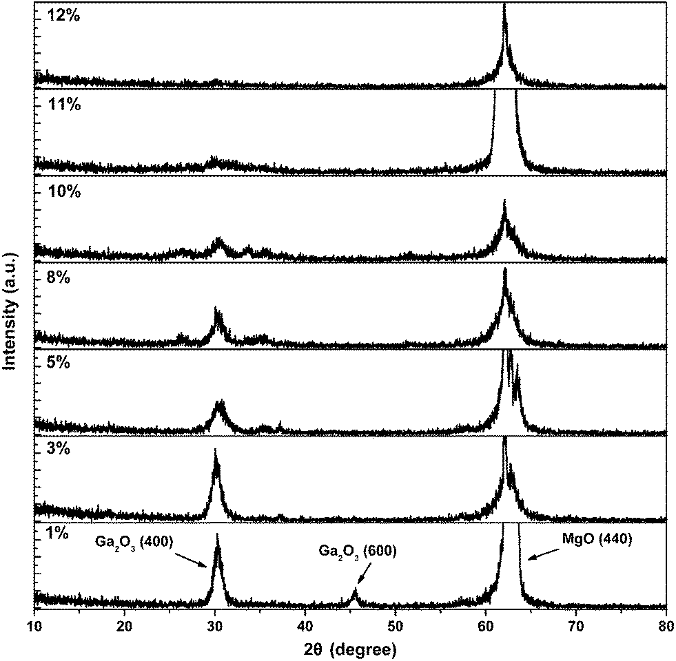 | ||
| Fig. 1 XRD spectra of the Ga2O3:Sn films with different doping levels. | ||
Fig. 2 exhibits the resistivity of the β-Ga2O3:Sn films as a function of Sn concentration. The undoped β-Ga2O3 film with the highest resistivity of about 109 Ω cm is used as a comparison. With the increase of Sn content, the resistivity of the sample decreases rapidly. The minimum resistivity value of about 5.21 × 10⁻² Ω cm is obtained for the 10% Sn-doped sample. Then the resistivity increases as the Sn content further raise to 11% and 12%. The decrease of resistivity can be explained by the presence of the Sn4+ ion. When some of the Ga3+ ions in the lattice are replaced by Sn4+ or some of the Sn ions as interstitial atoms are located in the lattice, conduction electrons can be produced, thus the resistivity of films is reduced. However, as Sn concentration increases further (over 10%), the crystalline quality of the films becomes poor. Consequently, the defects inside the films lead to the enhancement of the carrier scattering effect, and also the doping efficiency drops. As a result, the electrical resistivity increased markedly. The variations of resistivity, carrier concentration and mobility for the samples with 10% and 11% Sn doping levels are summarized in Table 1. It can be seen that the carrier density and mobility both drop obviously as the Sn content increases from 10% to 11%, resulting in the increase, resulting in the increase of the resistivity.
 | ||
| Fig. 2 The resistivity of the Ga2O3 films with different Sn concentrations. | ||
| Tin concentration (mol%) | Resistivity ρ (Ω cm) | Carrier concentration n (cm−3) | Mobility μ (cm2 V−1 s−1) |
|---|---|---|---|
| 10% | 5.21 × 10⁻² | 3.71 × 10¹⁹ | 3.35 |
| 11% | 4.99 × 10⁻¹ | 4.34 × 10¹⁸ | 2.88 |
The temperature dependent Hall measurements are performed on 10% Sn-doped film in vacuum (<10 Pa) and the results are shown in Fig. 3. The electrical properties of the film exhibit a semiconductor-like behavior. As the temperature rises from low to room temperature, the resistivity and Hall mobility decrease, and the carrier concentration increases. At low temperature, the Hall mobility stays at a high level, which can be attributed to the weak lattice scattering at the very low temperature. As the temperature rises up to room temperature, the lattice vibration aggravates, leading to the enhancement of phonon scattering and the decrease of Hall mobility. These results demonstrate that Sn is an effective n-type dopant for β-Ga2O3 films and the resistivity can be intentionally reduced by over ten orders of magnitude by Sn doping.
 | ||
| Fig. 3 Resistivity (ρ), carrier concentration (n) and Hall mobility (μ) of β-Ga2O3 films with 10% Sn doped as a function of reciprocal temperature. | ||
The cross-section area and surface morphologies of the 10% Sn-doped β-Ga2O3 film are revealed by the SEM micrographs. From Fig. 4(a), the obvious boundary between the substrate and film can be observed, and the thickness of the film is about 470 nm. In Fig. 4(b), an orderly surface with well-defined crystallites is obtained. The boundaries of each crystalline particle can be seen clearly.
 | ||
| Fig. 4 The SEM image for the 10% Sn-doped β-Ga2O3 film: (a) the cross-section area and (b) surface. | ||
Further structural properties of the sample with 10% Sn content are studied by HRTEM. Fig. 5 shows the HRTEM and SAED micrographs of the interface between the film and substrate. The incident electron beam is parallel to the [1![[1 with combining macron]](https://www.rsc.org/images/entities/char_0031_0304.gif) 0] direction of the MgO substrate. In the HRTEM image, the spacings of the observed lattice planes in the film area are about 0.297 nm and 0.468 nm, corresponding to the β-Ga2O3 (400) and (01) planes, respectively. For the substrate, the interplane spacings marked by the white lines are 0.144 and 0.234 nm which are consistent with MgO (440) and (222), respectively. The diffraction spots of β-Ga2O3 (400), β-Ga2O3 (01), MgO (440), MgO (222) can be seen clearly in the SAED micrograph. The results of HRTEM and SAED show a clear orientation relationship of β-Ga2O3 (100) ‖ MgO (110) with β-Ga2O3 (01) ‖ MgO (111).
0] direction of the MgO substrate. In the HRTEM image, the spacings of the observed lattice planes in the film area are about 0.297 nm and 0.468 nm, corresponding to the β-Ga2O3 (400) and (01) planes, respectively. For the substrate, the interplane spacings marked by the white lines are 0.144 and 0.234 nm which are consistent with MgO (440) and (222), respectively. The diffraction spots of β-Ga2O3 (400), β-Ga2O3 (01), MgO (440), MgO (222) can be seen clearly in the SAED micrograph. The results of HRTEM and SAED show a clear orientation relationship of β-Ga2O3 (100) ‖ MgO (110) with β-Ga2O3 (01) ‖ MgO (111).
 | ||
| Fig. 5 Cross-sectional HRTEM and SAED micrographs of the interface between the 10% Sn-doped β-Ga2O3 film and the MgO substrate. | ||
Fig. 6 shows the XPS spectra for the β-Ga2O3:Sn film with 10% Sn content. Fig. 6(a) is the survey spectrum of the film, which indicates the peaks of C1s, Ga2p, O1s, Sn3d, Ga3s and Ga3d. Fig. 6(b–d) are the high resolution spectra of Ga2p, Sn3d and O1s peaks, respectively. In Fig. 6(b), two symmetrical peaks of Ga2p1/2 located at 1144.1 eV and Ga2p3/2 located at 1117.3 eV can be observed. The separation distance between these two peaks is about 26.8 eV, which is in good agreement with the binding energy of the Ga2p (Δ = 26.8 eV).20,21 In Fig. 6(c), the tin core levels Sn3d5/2 and Sn3d3/2 observed at 486.4 and 494.8 eV, respectively, with a peak-to-peak separation of 8.4 eV confirm the formation of Sn.22 The O1s peak is located at about 530.5 eV. Using the Gaussian Fitting method, the peak can be resolved into two separate peaks. The signal at 530.5 eV is attributed to lattice oxygen in the β-Ga2O3:Sn film.23,24 The other peak at 531.7 eV can be regard as the C/O or OH− adsorbed species on the surface.25 The compositional ratio of Sn-to-Ga is about 12%, which is larger than the expected value of 10%. The analysis above illustrates that the obtained film is Sn-doped β-Ga2O3.
 | ||
| Fig. 6 XPS spectra of the 10% Sn-doped β-Ga2O3 film. | ||
The optical transmittance spectra for the β-Ga2O3:Sn films as a function of wavelength in the range of 200–800 nm are shown in Fig. 7(a). The average transmittance of all the films in visible rage exceeded 87%. For the direct band gap transition semiconductors, the absorption coefficient α and optical band gap (Eg) are related by αhν = A(hν − Eg)1/2.26,27 Where A is a constant, ν is the frequency of the incident photon and h is the Planck's constant. The optical band gap can be estimated by extrapolating the straight line portion of this plot to the energy axis. The optical gaps for the films as a function of the Sn content are shown in Fig. 7(b). As the Sn content increases, Eg decreases in initial with a minimum value of 4.12 eV obtained for the 10% Sn-doped sample, and then the Eg increases. The variation trend of Eg is consistent with that of resistivity. The decrease of Eg can be attributed to two reasons: first the band gap of SnO2 is narrower than that of β-Ga2O3; second the band gap narrowing effect.28,29 For the heavily doped semiconductors, the band tail and impurity band will be generated; as the doping concentration increases from 0 to 10%, the band tail and impurity band extended, which makes the band tail and impurity band overlap. As a result to the actual width of the forbidden band becomes narrower. But as the Sn concentration increases further (over 10%), the crystalline quality declined obviously, resulting in the broadening of the band gap.
 | ||
| Fig. 7 (a) The optical transmittance spectra of β-Ga2O3:Sn samples. The plot of (αhν)2 as a function of photon energy hν are shown in the inset. (b) Eg of the β-Ga2O3:Sn films as a function of Sn content. | ||
IV. Conclusions
In conclusion, β-Ga2O3:Sn films have been deposited on MgO (110) substrate by MOCVD at 700 °C. Sn is an effective n-type impurity and can reduce the resistivity by over ten orders of magnitude. The sample with 10% Sn content has the lowest resistivity of about 5.21 × 10⁻² Ω cm with a carrier density of 3.71 × 1019 cm−3. The micro-structure analysis of the 10% Sn-doped sample reveal a clear orientation relationship of β-Ga2O3 (100) ‖ MgO (110) with β-Ga2O3 (01) ‖ MgO (111). The average transmittance of all the samples exceeded 87% in visible range. The film grown with 10% Sn content has the minimum optical band gap of about 4.12 eV. The variation trend of Eg is consistent with that of resistivity. The deposition of high quality β-Ga2O3:Sn film with excellent electrical properties can be used in many fields such as short wavelength light emitting devices, transparent transistors, quantum-well devices and solar cells.
Acknowledgements
This work is financially supported by the National Natural Science Foundation of China (Grant no. 51072102).References
- N. Zebbar, M. Trari, M. Doulache, A. Boughelout and L. Chabane, Appl. Surf. Sci., 2014, 292, 837 CrossRef CAS PubMed.
- A. Kar, M. A. Stroscio, M. Dutta, J. Kumari and M. Meyyappan, Appl. Phys. Lett., 2009, 94, 101905 CrossRef PubMed.
- T. Koida and M. Kondo, J. Appl. Phys., 2006, 99, 123703 CrossRef PubMed.
- Z. Hajnal, J. Miró, G. Kiss, F. Réti, P. Deák, R. C. Herndon and J. Michael Kuperberg, J. Appl. Phys., 1999, 86, 3792 CrossRef CAS PubMed.
- M. Orita, H. Ohta, M. Hirano and H. Hosono, Appl. Phys. Lett., 2000, 77, 4166 CrossRef CAS PubMed.
- S. C. Vanithakumari and K. K. Nanda, Adv. Mater, 2009, 21, 3581 CrossRef CAS.
- H. Hosono, Thin Solid Films, 2007, 515, 6000 CrossRef CAS PubMed.
- T. Schwebel, M. Fleischer, H. Meixner and C.-D. Kohl, Sens. Actuators, B, 1998, 49, 46 CrossRef CAS.
- K. Matsuzaki, H. Hiramatsu, K. Nomura, H. Yanagi, T. Kamiya, M. Hirano and H. Hosono, Thin Solid Films, 2006, 496, 37 CrossRef CAS PubMed.
- M. Passlack, N. E. J. Hunt, E. F. Schubert, G. J. Zydzik, M. Hong, J. P. Mannaerts, R. L. Opila and R. J. Fischer, Appl. Phys. Lett., 1994, 64, 2715 CrossRef CAS PubMed.
- J. Zhang, C. Xia, Q. Deng, W. S. Xu, H. S. Shi, F. Wu and J. Xu, J. Phys. Chem. Solids, 2006, 67, 1656 CrossRef CAS PubMed.
- E. G. Víllora, K. Shimamura, Y. Yoshikawa, T. Ujiie and K. Aoki, Appl. Phys. Lett., 2008, 92, 202120 CrossRef PubMed.
- P. Gollakota, A. Dhawan, P. Wellenius, L. M. Lunardi and J. F. Muth, Appl. Phys. Lett., 2006, 88, 221906 CrossRef PubMed.
- S. Ohira, N. Suzuki, N. Arai, M. Tanaka, T. Sugawara, K. Nakajima and T. hishido, Thin Solid Films, 2008, 516, 5763 CrossRef CAS PubMed.
- J. Hao and M. Cocivera, J. Phys. D: Appl. Phys., 2002, 35, 433 CrossRef CAS.
- C. H. Liang, G. W. Meng, G. Z. Wang, Y. W. Wang and L. D. Zhang, Appl. Phys. Lett., 2001, 78, 3202 CrossRef CAS PubMed.
- S. Kumar, C. Tessarek, S. Christiansen and R. Singh, Journal of Alloys and Compounds, 2014, 587, 812 CrossRef CAS PubMed.
- S. Schulz, G. Bendt, W. Assenmacher, D. Sager and G. Bacher, Chem. Vap. Deposition, 2013, 19, 347 CrossRef CAS.
- W. Mi, J. Ma, Z. Zhu, C. Luan, Y. Lv and H. D. Xiao, J. Cryst. Growth, 2012, 354, 93 CrossRef CAS PubMed.
- H. D. Xiao, H. L. Ma and C. S. Xue, Mater. Chem. Phys., 2007, 101, 99 CrossRef CAS PubMed.
- H. Hellwig, K. Xu, D. Barreca, A. Gasparotto, M. Winter, E. Tondello, R. A. Fischer and A. Devi, Eur. J. Inorg. Chem., 2009, 1110 CrossRef.
- C. Luan, Z. Zhu, W. Mi and J. Ma, J. Alloys Compd., 2014, 586, 426 CrossRef CAS PubMed.
- F. M. Amanullah, K. J. Pratap and V. H. Babu, J. Mater. Sci. Eng. B, 1998, 52, 93 CrossRef.
- M. Hellwig, K. Xu, D. Barreca, A. Gasparotto, B. Niermann, J. Winter, H. W. Becker, D. Rogalla, R. A. Fischer and A. Devi, ECS Trans., 2009, 25, 617 CAS.
- X. J. Zhang, H. L. Ma and Q. P. Wang, et al., Chin. Phys. Lett., 2005, 22, 995 CrossRef CAS.
- D. Beena, K. J. Lethy, R. Vinodkumar, V. P. Mahadevan Pillai, V. Ganesan, D. M. Phase and S. K. Sudheer, Appl. Surf. Sci., 2009, 255, 8334 CrossRef CAS PubMed.
- G. Mills, Z. G. Li and D. Meisel, J. Phys. Chem., 1988, 92, 822 CrossRef CAS.
- H. Q. Zheng, H. Wang, P. H. Zhang, Z. Zeng, K. Radahakrishnan, S. F. Yoon and G. I. Ng, Solid-State Electron., 2000, 44, 37 CrossRef CAS.
- H. T. Luo, W. Z. Shen, Y. H. Zhang and H. F. Yang, Phys. B, 2002, 324, 379 CrossRef CAS.
| This journal is © The Royal Society of Chemistry 2014 |