M. K. Devaraju
*,
Q. D. Truong
,
T. Tomai
and
I. Honma
*
Institute of Multidisciplinary Research for Advanced Materials, Tohoku University, Katahira 2-1-1, Aoba-ku, Sendai 980-8577, Japan. E-mail: devaraju113@gmail.com; i.honma@tagen.tohoku.ac.jp; Tel: +81-8022-217-5186
First published on 29th May 2014
Lithium ion battery materials improve the current technology to store electrical energy for the creation of green environment. The synthesis of lithium ion battery materials is crucial for energy applications in mobile electronic devices to plug-in hybrid electric vehicles. This review summarizes the recent progress made to synthesize lithium ion battery materials via supercritical fluid methods, and particularly, its application towards the synthesis of layered transition metal oxides, spinel structured cathodes, lithium metal phosphates, lithium metal silicates and lithium metal fluorophosphates. The structure, particle size, morphology and electrochemical properties of cathode materials are discussed. From the perspective of material synthesis, supercritical fluid methods are economical and have several advantages such as phase purity, morphology control and size tuning down to 5 nm, which would significantly impact the performance of lithium ion batteries.
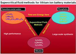
Since the discovery of layered transition metal oxides as cathode and graphite/hard carbon as anode material, several new cathode and anode materials have been investigated. Till now, only few cathode materials, such as LiCoO2, LiNi1−x−yCoxMnyO2, LiMn2O4 and LiFePO4, have been extensively studied.6 LiCoO2 or LiNi1−x−yCoxMnyO2 cathode materials offer several advantages such as high specific capacity, high operating voltage, long cycle life and easy synthesis.6a,6b Oxygen evolution at high operating voltage makes them very promising for high voltage applications. LiMn2O4 also exhibits several advantages such as low cost, high performance rate, higher abundance of Mn and good thermal stability, thus it is considered to be a good cathode candidate for power tool applications.6c,6d After the investigation of LiFePO4 by J. B. Goodenough,6e the LiFePO4 olivine structured cathode material has been widely studied due to its excellent characteristics such as cycle stability, low cost, environmental benignity, and ease of manufacturing, making this material the best cathode candidate for lithium ion batteries. However, the properties of cathode materials depend on the method of synthesis, nature of starting materials, reaction media, and reaction kinetics. Moreover, phase purity, homogeneity, particle size, morphology and cation order are amongst other critical parameters for high performance batteries.3 Recently, orthosilicates and fluorophosphates are being explored for energy storage applications.7,8
In recent years, several synthetic routes have been developed to produce various cathode and anode materials. For years, solid state reaction has been widely used to synthesize lithium ion battery materials.6e,9 Solid state reaction involves the mixing of metal oxides or carbonates under prolonged high temperature, which is time-consuming and uses a lot of energy. Furthermore, the resulting products show low homogeneity and purity, and large particle size. The challenges in terms of material design for lithium ion battery are ongoing. Currently, the development of novel and advanced energy storage materials with various sizes and shapes, and three dimensional nano/microstructures with excellent performance are the most important challenges in material design for lithium ion battery. The discovery of new material designs is the main focus of several prominent research groups in the field of electrode materials design across the world.
Recently, various methods have been developed to prepare lithium battery materials such as the sol–gel method,10,11 co-precipitation,12,13 mechanochemical activation,14,15 and spray technology.16 However, all these methods have limitations regarding practical applications. Therefore, solution processes such as hydrothermal, solvothermal, ion exchange and supercritical fluid methods have been extensively studied.17 Among the solution processes for the synthesis of electrode materials, the supercritical fluid method attracts much attention because it allows the design of inorganic functional materials with variety of shapes, sizes, and hierarchical structures, ensuring one-pot synthesis.18 Supercritical fluid method is a commercially viable process due to energy consumption and the possibility of large scale synthesis.
In this review, we summarize the progress of supercritical fluid methods for the development of lithium ion battery materials such as lithium transition metal oxides, lithium metal phosphates, fluorophosphates and lithium metal silicates.
![]() | ||
Fig. 1 (A) Substance (water) at supercritical region by changing temperature and pressure. (B) Comparison of the supercritical fluid method with other synthetic methodologies. |
Compared to various synthetic methodologies, from high temperature solid state reaction method to low temperature hydrothermal/solvothermal process, supercritical fluid methods have been considered green and environmentally benign processes because of their numerous merits (Fig. 1B). First, the time requirement for material synthesis is from few minutes (continuous synthesis) to less than few hours (batch synthesis), which reduces energy consumption and time. The synthesis temperature is less than 500 °C, depending on the type of materials processing, which reduces energy consumption and cost. Particles with less than few nanometers in size can be synthesized, where size defines the property of materials. This is a relatively low temperature process and is easily applicable to large scale synthesis. Recently, the large scale synthesis of LiFePO4 electrode materials with 1000 tones per year was initiated at Hanwha Chemical, Korea.
Supercritical fluid methods for synthesizing cathode materials and their properties are listed in Table 1.
Materials | System | P/T MPa/°C | Particle size (nm) | Morphology | Capacity (mA h g−1) | Ref. | |
---|---|---|---|---|---|---|---|
a NA: not available. | |||||||
Transition metal oxides | Oxides | ||||||
LiCoO2 | Continuous | 30/400 | 900–1000 | Rough shape | N.A. | 20 | |
LiCoO2 | Batch | 30/400 | 2000–3000 | Rough shape | N.A. | 21 | |
LiCoO2 | Continuous | N.A./300–400 | 600–1000 | Rough shape | N.A. | 21 | |
LiCoO2 | Continuous | 30/400 | 100–300 | Nanoplates | N.A. | 22 | |
LiMn2O4 | Batch | 30/400 | 300–500 | Spherical | 130 | 23 | |
LiMn2O4 | Continuous | 30/380 | 50–300 | Irregular shape | N.A. | 24 | |
LiNCMO2 | Batch | 30/400 | 600–1000 | Pyramid | 180 | 25 | |
Phosphates | LiFePO4 | Batch | 33.5/300–400 | 500–1200 | Irregular shape | N.A. | 26a |
LiFePO4 | Batch | 30/389 | 100 | Spherical/rod | 140 | 26b | |
LiFePO4 | Continuous | N.A./300–385 | 50–130 | Spherical | N.A. | 26c | |
LiFePO4 | Continuous | 25/400 | 20 | Spherical | 75 | 27 | |
LiFePO4 | Batch | 40/400 | 15 | Spherical | 165 | 28 | |
LiFePO4 | Batch | 40/400 | 50 × 200 | Rod-hierarchy | 152 | 29 | |
LiFe/MnPO4 | Batch | 40/400 | 20 × 100 | Nanorods | 158 | 30, 31 | |
LiMnPO4 | Batch | 40/400 | 20 × 100 | Nanorods | 158 | 30, 31 | |
LiFePO4 | Continuous | 25/400 | 25 | Irregular | 105 | 32, 33 | |
LiFePO4 | Batch | N.A./400 | 50 × 2000 | Spindle | 138 | 34 | |
LiFePO4 | Batch | 25/100 | 2000 | Porous | 162 | 35 | |
LiFePO4 | Batch | 10/400 | 3.7–4.6 (b-axis) | Nanosheets | 164 | 37 | |
LiMnPO4 | Batch | 10/400 | 3.7–4.6 (b-axis) | Nanosheets | 157 | 37 | |
LiCoPO4 | Batch | 10/400 | 3.7–4.6 (b-axis) | Nanosheets | 153 | 37 | |
LiCoPO4 | Batch | 40/400 | 5–15 (b-axis) | Nanoplates | 135 | 38a | |
LiCoPO4 | Batch | 40/400 | 50 × 1000 | Nanorods | 130 | 38b | |
LiCoPO4 | Batch | 40/400 | 50 × 200 | Nanoplates | 121 | 38b | |
Silicates | Li2FeSiO4 | Batch | 40/400 | 1–5 | Nanosheets | 340 | 42 |
Li2MnSiO4 | Batch | 40/400 | 1–5 | Nanosheets | 350 | 42 | |
Li2MnSiO4 | Batch | N.A./300 | 10 | Spherical | 313 | 43 | |
Li2MnSiO4 | Batch | 38/400 | 500 | Hierarchy | 292 | 44 | |
Li2FeSiO4 | Batch | 38/400 | 50 × 400 | Nanorods | 177 | 45 | |
Li2CoSiO4 | Batch | 38/350 | 200 | Irregular shape | 107 | 46 |
Supercritical fluid methods for the synthesis of lithium transition metal oxides were realized by K. Kanamura et al.20 in 2000 and T. Adschiri et al.21 in 2001. K. Kanamura et al. used flow type supercritical water synthesis for the synthesis of LiCoO2 particles. For the flow type synthesis of LiCoO2 particles, aqueous solutions of LiOH, Co(NO3)2 and distilled water or H2O2 were fed into a preheated supercritical chamber in three different lines, as shown in Fig. 2A. The synthesis was completed in 1 min, and the XRD of the as-synthesized particles showed layered rock type crystal structures, as shown in Fig. 2B. The XRD of LiCoO2 was compared with that of LiCoO2 prepared via the solid state reaction method. Slight differences in diffraction intensities were observed. However, a pure LiCoO2 phase was successfully synthesized via the flow type supercritical water method. Scanning electron microscopy images of LiCoO2 synthesized via the flow type supercritical water is shown in Fig. 2C. LiCoO2 particles with size of 1 μm in diameter were successfully synthesized. They also mentioned that particle size can be controlled up to a few nanometers by changing the reaction conditions.
![]() | ||
Fig. 2 (A) Flow type supercritical water synthesis. (B) XRD pattern of LiCoO2 particles. (C) SEM image of LiCoO2 particles. (Reprinted with permission from Electrochem. Solid-State Lett.)20 |
Adschiri et al.21 used both the batch type and flow type supercritical methods to synthesize LiCoO2 particles. They used starting materials such as LiOH and Co(NO3)2·6H2O. For the batch type synthesis, the aqueous solutions of LiOH and Co(NO3)2 were loaded into the batch type reactor, as shown in Fig. 3.
The synthesis was carried out at 400 °C and a pressure of 30 MPa in the presence of oxygen gas. They showed that a single phase of LiCoO2 can only be obtained at supercritical conditions in the presence of oxygen to oxidize all the divalent cobalt ions into trivalent ions during the synthesis of LiCoO2. The LiCoO2 particles synthesized via the flow type supercritical method have small diameters ranging from 600 nm to 1 μm, whereas the particles synthesized via the batch type supercritical method are 2–3 μm in size with a clear single crystal appearance.
Electrochemical analysis of the LiCoO2 particles, synthesized via the flow type supercritical hydrothermal method, was carried out using a solvent mixture of ethylene carbonate and diethylene carbonate containing 1 M LiClO4 as the electrolyte.
Stable discharge capacities of 110 mA h g−1 were obtained at 0.1 mA current density, and the authors claimed that the stable cyclic performance is due to single crystalline LiCoO2 particles.
Y. H. Shin et al.22 used a continuous hydrothermal method to synthesize LiCoO2 particles under supercritical water conditions using LiOH and Co(NO3)2·6H2O as starting materials. The effect of temperature, residence time, lithium hydroxides and hydrogen peroxide were investigated. Fig. 4A shows the XRD pattern of the as-synthesized LiCoO2 particles at various residence times of less than 1 min at 400–404 °C and 300 bar pressure with different concentrations of LiOH and Co(NO3)2. The XRD pattern shows a well-developed HT-LiCoO2 phase without any undesired product, and the intensity of the diffraction peaks increased with time. These results confirmed that pure phase LiCoO2 can be synthesized under continuous hydrothermal conditions. The authors observed that the use of excessive amounts of LiOH and H2O2 was beneficial to synthesize single phase LiCoO2 particles under supercritical conditions. The authors claim that the residence time of this particle preparation is shorter than for any other synthesis reports. The as-synthesized particles were 300–500 nm in size and had similar morphologies, as shown in Fig. 4B–E. Please refer to this article for detailed information on the investigation of LiCoO2 particles on changing various parameters. The authors did not measure the charge–discharge measurements for the synthesized particles. This report shows that the size of LiCoO2 can be controlled by controlling various parameters.
![]() | ||
Fig. 4 (A) XRD patterns of LiCoO2 synthesized at 400–404 °C with different residence times. (B)–(E) SEM images of LiCoO2 particles synthesized by the batch type supercritical method. (B) and (C) using 0.4 M LiOH, 0.02 M Co(NO3)2, 0.02 M H2O2 with residence time of 46 s and 58 s, respectively. (D)–(E) Temperature of 400 °C and 411 °C, respectively. (Reprinted with permission from Elsevier Ltd.)22 |
In 2005, K. Kanamura et al.23 used a hydrothermal process in supercritical water with heat treatment to synthesize LiMn2O4 cathode materials for rechargeable lithium batteries. The synthesis was carried out in a stainless steel cylindrical-type vessel (inner volume: 10 mL). For this synthesis, aqueous solutions of LiOH and Mn(NO3)2 were used with water in a 3:
1 molar ratio. The reaction was carried out with or without H2O2 at 400 °C for 15 min and at an inside pressure of 30 MPa. In addition, LiMn2O4 was synthesized by a solid-state reaction method for comparison. Fig. 5A shows the XRD pattern of the as-synthesized LiMn2O4 cathode material with various ratios of LiOH
:
Mn(NO3)2
:
H2O2. In all the cases, the obtained sample was LiMn2O4, and the diffraction peaks were comparable to that of the spinel LiMn2O4. However, a peak of Mn3O4 impurity was observed for the sample synthesized without H2O2, whereas no impurity was found for the samples prepared in the presence of H2O2. The authors claimed that adding H2O2 to supercritical water was effective for synthesizing single phase spinel LiMn2O4. The SEM images in Fig. 5B show LiMn2O4 prepared with various H2O2 ratios. They did not observe much difference in the particle size and shapes for the samples prepared with or without H2O2. When a high concentration of H2O2 was used during the synthesis, the synthesized samples had smaller size due to the influence of H2O2 on the nucleation of LiMn2O4. These particles were few hundreds of nanometers in size with similar shapes.
![]() | ||
Fig. 5 (A) XRD pattern and (B) SEM images of LiMn2O4 synthesized at 400 °C with different ratios of LiOH![]() ![]() ![]() ![]() |
The authors did not observe good charge–discharge performance for the LiMn2O4 cathode materials shown in Fig. 5A and B. Therefore, heat treatment was carried out to improve the electrochemical performance. The authors heat treated the sample at various temperatures (400–800 °C). Fig. 5C shows the SEM images of LiMn2O4 particles heat treated at 800 °C for 1 h, which shows well-defined crystals with 500 nm in size and almost the particles look like single crystals. The authors noticed that the size and shape of the particles changed with heating temperatures. The charge–discharge profile of LiMn2O4 particles heat treated at 800 °C for 1 h, shown in Fig. 5D, exhibit a good cyclic performance (inset in Fig. 5D). For the electrochemical measurement, 1 M LiClO4/EC + DEC was used as the electrolyte. The discharge capacity was higher than 125 mA h g−1 at 0.1 °C with a good cyclic performance. The observed capacity was comparable with that of the samples synthesized via the solid state reaction. The authors claimed that discharge capacity improved due to high crystallinity and crystallite size because of heat treatment, which leads to improved electrochemical performances. In 2006, Joo-Heon Lee et24 al attempted to synthesize LiMn2O4 particles in supercritical water using a flow type synthesis method with residence time of 30–40 s. The authors reported that the selective synthesis of LiMn2O4 was mainly dependent on the amount of OH− ion in the reactants. They synthesized LiMn2O4 particles using Mn(NO3)2·6H2O, LiOH, KOH, and LiNO3 solutions at 420 °C and a pressure of 300 bar.
Fig. 6A shows the XRD pattern of LiMn2O4 particles synthesized using 0.1 mol L−1 of LiOH and Li/Mn = 4. They observed that a single phase of LiMn2O4 particles can be synthesized using a high concentration of LiOH (0.1 mol L−1) but not with mixtures of LiNO3 or LiOH/LiNO3. The TEM image of LiMn2O4 synthesized using 0.1 mol L−1 of LiOH and Li/Mn = 4 is shown in Fig. 6B. The particles were spherical in shape with particle sizes less than 100 nm. The authors did not characterize the electrochemical performances of the LiMn2O4 particles.
![]() | ||
Fig. 6 (A) XRD pattern and (B) TEM image of LiMn2O4 synthesized using 0.1 mol L−1 of LiOH and Li/Mn = 4. (Reprinted with permission from Korean J. Chem. Eng.)24 |
Recently, Jae-Wook Lee et al.25 synthesized LiCoO2, over lithiated Li1.15CoO2 and LiNi1/3Co1/3Mn1/3O2 cathode materials using a batch type supercritical water method in the presence of argon or oxygen gas. LiOH and Co(NO3)2·6H2O were used as starting materials to synthesize LiCoO2 and Li1.15CoO2. For the synthesis of LiNi1/3Co1/3Mn1/3O2, LiOH, Ni(NO3)2·6H2O, Co(NO3)2·6H2O and Mn(NO3)2·6H2O were used as starting materials, and KOH solution was used to vary the pH of the solution. The synthesis was carried out at 400 °C for 10 min. Fig. 7A shows the XRD pattern of the as-synthesized Li1.15CoO2 and LiNi1/3Co1/3Mn1/3O2 cathode materials using KOH solution and purge oxygen gas at 400 °C for 10 min. The observed diffraction peaks were indexed as layered oxide structure based on a hexagonal α-NaFeO2 structure (space group: Rm). The XRD pattern of LiNi1/3Co1/3Mn1/3O2 was similar to that of Li1.15CoO2, and they both exhibited a layered structure.
![]() | ||
Fig. 7 (A) XRD patterns and (B)–(C) SEM images of Li1.15CoO2 and LiNi1/3Co1/3Mn1/3O2 particles synthesized in supercritical water with KOH solution and purge oxygen gas at 400 °C for 10 min. (D) Cyclic performance of Li1.15CoO2 and LiNi1/3Co1/3Mn1/3O2 particles. (Reprinted with permission from Elsevier Ltd.)25 |
Fig. 7B and C show the SEM images of the Li1.15CoO2 and LiNi1/3Co1/3Mn1/3O2 cathode materials prepared using aqueous KOH solution and oxygen purge gas. The particles were 300 nm to 1 μm in size with cubic shape, and they exhibited clear crystal boundaries without hard agglomerations. The authors observed initial discharge capacities of 149 and 180 mA h g−1 for Li1.15CoO2 and LiNi1/3Co1/3Mn1/3O2 particles, respectively, at a current density of 16 mA g−1 at room temperature. The cyclic performance was measured within a voltage window of 2.5–4.5 V for Li1.15CoO2 and LiNi1/3Co1/3Mn1/3O2 and at 80 m Ah g−1 for 30 cycles. The LiNi1/3Co1/3Mn1/3O2 cathode material showed better cyclability than Li1.15CoO2 particles (Fig. 7D). The authors claimed that the superior cyclability of LiNi1/3Co1/3Mn1/3O2 cathode material is due to the characteristic of cathode powders. The authors also investigated the rate performance of Li1.15CoO2 and LiNi1/3Co1/3Mn1/3O2 particles using 1 M LiPF6 electrolyte mixed with ethylene carbonate (EC) and diethyl carbonate (DEC) in a 1:
1 volume ratio. The abovementioned studies highlight the importance of supercritical fluid techniques for the preparation of layered oxide materials with controlled composition, size, and morphology, and for the improvement of their electrochemical properties.
Further research must be carried out on layered metal oxides and spinel structure materials. Metal coating or doping with effective cations could improve the capacity of these materials by enhancing their cyclability. The observation of full theoretical capacity of these materials could be possible via different approaches by controlling their structure, size and morphology.
In 2005, J. Lee et al.26a reported the supercritical water synthesis of LiFePO4 particles using batch type reactors. LiFePO4 was synthesized by dissolving FeSO4·7H2O, H3PO4 and LiOH in distilled water. The synthesis was carried out in a 250 mL stainless steel autoclave. The authors investigated the effect of temperature, time, pH and reactant concentrations on the morphology and size of LiFePO4 particles. Fig. 8A shows the XRD patterns of LiFePO4 synthesized at various temperatures. All the diffraction peaks are comparable to the standard pattern (JCPDS 40-1499). The XRD pattern was compared with some of the previously reported studies. They observed increased peak intensity with increasing reaction temperature, and also observed changes in the morphology of the LiFePO4 particles. Fig. 8B shows the SEM image of LiFePO4 particles synthesized at 387 °C for about 1 h. The obtained particles were smaller, forming soft and uniform agglomerations when compared to the particles synthesized at low and subcritical temperatures.
![]() | ||
Fig. 8 (A) XRD patterns of LiFePO4 synthesized at different temperatures. (B) SEM image of LiFePO4 synthesized at 387 °C for 10 min (reprinted with permission from Elsevier Ltd.)26a (C)–(D) SEM images of LiFePO4 synthesized at 389 °C via reaction A and reaction B, respectively. (E) Discharge profiles of LiFePO4 shown in Fig. 8D (reprinted with permission from Elsevier Ltd.).26b (F) LiFePO4 particles synthesized by continuous hydrothermal synthesis (reprinted with permission from Elsevier Ltd.).26c |
In 2006, the same group26b generated LiFePO4 micro- and nanoparticles in supercritical water using two types of synthesis routes. For synthesis A, the authors used acidic stock solutions of Li3PO4 and o-H3PO4 and a basic stock solution of NH4OH in distilled and deionized water to control pH. The stock solutions and 3.75 g of FeSO4·7H2O granules were added to an autoclave in argon gas. The following reaction was expected:
Li3PO4 + 2H3PO4 + 3(FeSO4·7H2O) + 6NH4OH → 3LiFePO4 + 3(NH4)2SO4 + 27H2O. |
The reaction was terminated after 1 h. SEM images of the obtained particles are shown in Fig. 8C. These particles were obtained at 389 °C and pH 5.26. The micron-sized particles exhibited a rod-like morphology.
For synthesis route B, the authors used NaOH to control the pH and Li3PO4 as a source of both lithium and phosphate ions. First, 150 mL of an aqueous solution of FeSO4·7H2O was prepared, and NaOH solution was added to adjust the pH of the resulting mixture to any desired value. Then, the reaction was carried out. The synthesis reaction was summarized as follows:
Li3PO4 + FeSO4·7H2O → LiFePO4 + 3(NH4)2SO4 + LiSO4 + 7H2O |
Fig. 8D shows the SEM images of LiFePO4 particles with particle size less than 100 nm. The authors observed that temperature was the dominant factor, whereas pH had little effect on particle size and shape. They investigated the electrochemical properties of LiFePO4 particles obtained via synthesis route B. The discharge capacities measured at various current densities are shown in Fig. 8E. A discharge capacity of 140 mA h g−1 was observed at 0.1 °C, and 75% of this capacity was retained at 1 °C, corresponding to 82% of the theoretical capacity. The authors claim that this capacity is higher than for LiFePO4 synthesized from other methods.
C. Xu et al.26c proposed a continuous hydrothermal synthesis of LiFePO4 particles in subcritical and supercritical water. They used flow type reactors in which degassed solutions of FeSO4 in H3PO4 (solution 1) and LiOH (solution 2) came into contact with hot compressed water (solution 3) in a mixing tee, resulting in the precipitation of LiFePO4 particles according to the reaction:
FeSO4 + H3PO4 + 3LiOH → LiFePO4 + Li2SO4 + 3H2O |
The authors investigated the effect of temperature, water flow rate, and concentration, and compared the batch type synthesis with flow type hydrothermal synthesis. Fig. 8F shows an SEM image of LiFePO4 particles of about 40 nm in size, which were obtained by continuous hydrothermal synthesis. This method has the advantage of maintaining the crystal size below 50 nm. However, the authors did not report the electrochemical performance of this material.
In 2009, A. Aimable et al.27 used a similar method to synthesize LiFePO4 nanoparticles. For this synthesis, reactive solution 1 was prepared by dissolving (NH4)2Fe(SO4)2·6H2O (19.6 g, 0.1 mol L−1) and o-H3PO4 (4.9 g, 0.1 mol L−1) in deionized water (500 mL). Reactive solution 2 was prepared by dissolving LiOH·H2O (7.8 g, 0.375 mol L−1) in deionized water (500 mL). TEM images of particles obtained by continuous hydrothermal synthesis are shown in Fig. 9A. The particles were 50 nm in diameter with clear crystal habits. The electrochemical properties were determined for two samples, namely SC1 composed of aggregated particles (reaction time: 6 s) and SC2 composed of non-agglomerated particles (reaction time: 12 s). The electrode made from sample SC2 exhibited a unique flat charge and a discharge curve at 3.5 V with almost no polarization (Fig. 9B). It was observed that 0.45 Li was inserted reversibly in this material, corresponding to a capacity of 75 mA h g−1. The authors demonstrated that 50 nm sized particles can be synthesized with good electrochemical performance.
![]() | ||
Fig. 9 (A) TEM images of particles obtained by continuous hydrothermal synthesis. (B) Galvanostatic cycling of hydrothermally synthesized LiFePO4 at two reaction times of SC1 6 s and SC2 12 s with charge–discharge rates of C/10, and SC2 with a low cycling rate of C/100. (Reprinted with permission from Elsevier Ltd.)27 |
In 2009, our group reported surface modified LiFePO4/C nanocrystals using supercritical batch reactors.28 In situ carbon coated LiFePO4/C nanocrystals were synthesized using FeC2O4·2H2O, NH4H2PO4, LiOH, ascorbic acid and oleic acid as starting materials, and ethanol was used as the solvent. The synthesis was carried out at 400 °C for about 10–30 min. The HR-TEM images of the as-synthesized LiFePO4 nanocrystals in the presence of organic molecules under supercritical water conditions are shown in Fig. 10. The LiFePO4 nanocrystals were 15 nm in diameter when synthesized in the presence of oleic acid, which plays a key role in controlling particle size (Fig. 10B). The distinct lattice planes are shown in Fig. 10B and the SAED pattern.
![]() | ||
Fig. 10 (A) TEM images of LiFePO4 particles obtained in the presence of organic molecules. Inset: electron diffraction pattern of nanocrystals and amorphous carbon. (B) HR-TEM image showing lattice fringes. (C)–(D) Charge–discharge profile of as-synthesized LiFePO4 and heated LiFePO4 (reprinted with permission from Elsevier Ltd.)28 |
In 2010, our group reported the directed growth of nanoarchitectured LiFePO4 electrode by solvothermal synthesis using batch reactors under supercritical fluid condition.29 The synthesis used ethylene glycol as a solvent and oleic acid or hexane as co-solvents. The synthesis was carried out at 400 °C for 10 min.
Fig. 11A shows the TEM images of nanoflower-like structures with lengths ranging from 200–400 nm and widths of less than 100 nm in diameter. Different kinds of morphologies were obtained by changing the organic solvents. Fig. 11B shows the charge–discharge profile of LiFePO4 after heating at 600 °C. The flower-like microstructures exhibit capacities as high as 154 mA h g−1, with a slope-like plateau showing the effect of nanosize particles due to high surface area. The ED pattern shown in Fig. 10A (top inset), with bright spots of well-defined diffraction patterns of olivine phase, suggests highly crystalline LiFePO4/C nanocrystals. The SAED profile, shown in Fig. 10A, reveals that the LiFePO4 nanocrystals form single-crystalline material. Fig. 10C shows the charge–discharge profile of the as-synthesized LiFePO4 nanocrystals, indicating small capacity. Therefore, the LiFePO4/C nanocrystals were heated at 500 °C to generate a conductive carbon coating, which improved discharge capacity (Fig. 10D). This process produced crystals that were uniform in shape, and consistently less than 20 nm in size, for better electrochemical performance upon heating.
![]() | ||
Fig. 11 (A) TEM image of LiFePO4 nanostructure synthesized in EG-oleic acid. (B) Charge–discharge profile of LiFePO4 at different current densities. (Reprinted with permission from Elsevier Ltd.)29 (C)–(D) TEM images of LiFePO4 and LiMnPO4 particles synthesized in the presence of oleylamine. (E) Charge–discharge profiles of LiFePO4 at different current densities. (F) Charge–discharge profile of LiMnPO4 particles. (Reprinted with permission from The Royal Society of Chemistry.)30 |
After this work, in 2010, supercritical ethanol process to prepare colloidal LiMPO4 (M = Fe and Mn) nanocrystals was proposed by our group.30 The synthesis involved metal chloride dissolved in oleylamine and ethanol at 60 °C for 1 h, followed by the addition of o-H3PO4 solution and Li acetyl acetonate. The supercritical reaction was carried out at 250–400 °C for 4–10 min. Fig. 11C and D show the colloidal nanocrystals of LiFePO4 and LiMnPO4 adopted nanoplate- and nanorod-like morphology, respectively. The colloidal particles were 15–20 nm in diameter in the presence of oleylamine but 70–90 nm in diameter in the absence of oleylamine. Thus, oleylamine plays an important role in reducing the particle size because it can absorb specific crystal planes and inhibit crystal growth under supercritical conditions. Fig. 11E and F show the charge–discharge profile of LiMPO4 (M = Fe and Mn) colloidal nanocrystals after conductive polymer coating and heat treatment. At a rate of 0.1 C, the LiFePO4 nanocrystals exhibited the highest capacity of 158 mA h g−1, whereas LiMnPO4 nanocrystals exhibited a capacity of 62 mA h g−1 at 0.1 C. Further, to improve the discharge capacities of LiMnPO4 nanocrystal, a detailed investigation was reported in 2011 from our group,31 where we showed that the discharge capacities change with the size of the particles. Discharge capacities of 123 and 92 mA h g−1 were obtained for particles of 100 nm and 80 nm sizes with values as high as 152 mA h g−1 for 20 nm LiMnPO4 nanocrystals. These results show that proper conductive carbon coating of colloidal nanocrystals could provide full discharge capacity. The supercritical method using batch reactors, in the presence of selected starting materials and solvents, has the potential to synthesize nanosized lithium battery materials.
In 2011, S. A. Hong et al.32 reported nanosized lithium iron phosphate (LiFePO4) particles using a continuous supercritical hydrothermal synthesis method at 25 MPa and 400 °C at various flow rates. The authors used a modified continuous process to control the properties of LiFePO4 in supercritical water including purity, crystallinity, atomic composition, particle size, surface area, and thermal stability, which were compared with those of LiFePO4 prepared via a solid state method.
The SEM images of LiFePO4 particles prepared using the supercritical hydrothermal synthesis method are shown in Fig. 12A–C. Particle sizes of 200–800 nm were obtained with the lowest precursor solution flow rate (1.7 g min−1), as shown in Fig. 12A. At higher precursor solution flow rate (3 g min−1), the synthesized particles were smaller and uniform, exhibiting soft aggregation. When the flow rate was increased from 9 g min−1 to 18 g min−1, the particles were smaller and adopted a rod-shape morphology (Fig. 12C).
![]() | ||
Fig. 12 (A)–(C) SEM images of LiFePO4 particles synthesized via supercritical hydrothermal synthesis method at different flow rates. (D) Cyclic performance of the LiFePO4 particles shown in (A)–(C) in comparison with LiFePO4 particles prepared via solid state reaction method. (Reprinted with permission from Elsevier Ltd.)32 |
The cyclic performance of LiFePO4 particles synthesized at three different precursor solution flow rates (Fig. 12A–C) are shown in Fig. 12D, and the results were compared to LiFePO4 particles prepared by solid state reaction. The LiFePO4 particles (Fig. 12A–C) exhibit a low initial capacity, compared to the solid-state synthesized LiFePO4 (sample S, in Fig. 12D), which may be due to the presence of Fe3+ impurities in the as-synthesized LiFePO4 particles. However, LiFePO4 prepared with lower precursor solution flow rate (1.7 g min−1, E1 in Fig. 12D) showed larger capacities after 6 cycles, whereas LiFePO4 prepared with higher precursor solution flow rate (9 g min−1, E2 in Fig. 12D; 18 g min−1, E3 in Fig. 12D) showed larger capacities after 16–20 cycles than LiFePO4 prepared via solid-state reaction method. The superior cycle performance of the as-synthesized LiFePO4 particles can be attributed to the more homogeneous utilization of active materials, and shorter diffusion length of Li+ ions associated with smaller size particles. The authors obtained higher discharge capacities, in the range of 140–160 mA h g−1, after carbon coating of the LiFePO4 particles. This result shows that proper carbon coating of LiFePO4 particles could lead to higher discharge capacity. Furthermore, in 2013, the same group33 extended this work to investigate the effects of parameters such as reaction temperature, precursor, flow rate and residence time on LiFePO4 nanoparticles. The authors were able to further improve the cyclic performance of the carbon-coated LiFePO4 particles.
Recently, J. Yu et al.34 synthesized spindle-like carbon-coated LiFePO4 (LiFePO4/C) composites via a novel one-pot supercritical methanol method. FeCl2·4H2O, H3PO4, D-glucose and LiOH·H2O were used as starting materials. Methanol and benzyl alcohol were used as solvents. Fig. 13A shows the XRD pattern of LiFePO4/C particles synthesized using different concentrations of Li source (L1, L2 and L3 patterns). The peak position and intensity of all the samples were well-indexed to the standard peaks of LiFePO4 with olivine structure, and belonged to the space group Pnma. Some impurities were identified around 26–30° for L1-8 wt% sample. Fig. 13B and D show the TEM images of L2-8 wt% and L3-8 wt% samples, respectively. With 20 mmol Li source, the particles formed microplates with spindle like morphologies with a length of several micrometers. However at high Li concentration (30 mmol), large scale well-dispersed spindle-like microstructures with few micrometers in length were observed, as shown in Fig. 13C.
![]() | ||
Fig. 13 (A) XRD patterns of LiFePO4 particles synthesized using different concentrations of Li and the one-pot supercritical methanol method. (B)–(C) TEM images of LiFePO4 particles synthesized using 20 mmol and 30 mmol of Li source. (D) Charge–discharge profile of the LiFePO4 particles shown in (B) and (C). (Reprinted with permission from Elsevier Ltd.)34 |
The charge–discharge profiles of LiFePO4 particles synthesized with 20 mmol Li source (L2 in Fig. 13D) or 30 mmol Li (L3 in Fig. 13D) were recorded in the 2.0–4.5 V range. Discharge capacities of 108 and 135 mA h g−1 were observed at 0.2 C for L2 and L3 samples, as shown in Fig. 12D. These results suggest that LiFePO4 particles, with different morphologies and proper carbon coating, can produce high capacity.
In 2013, M. Xie et al.35 reported a template-free method to prepare porous LiFePO4 using supercritical carbon dioxide. The authors proposed the following mechanism to synthesize porous LiFePO4 particles by introducing scCo2. First, LiFePO4 was prepared by the hydrothermal method, which was followed by scCo2 treatment in a supercritical fluid reactor. Fig. 14A shows the mechanism for the synthesis of porous LiFePO4 under supercritical carbon dioxide conditions. The A1 sample was the as-prepared LiFePO4 by hydrothermal method, which was treated without scCO2 (A2) or with scCO2 at these conditions: 100 bar for 24 h (A3), 100 bar for 48 h (A4), or 250 bar for 48 h (A5) at 100 °C. Fig. 14B shows the XRD patterns for samples A1–A5. The observed diffraction peaks are well-matched with the standard LiFePO4 of orthorhombic structure (JCPDS 40-1499). All the characteristic peaks are clearly indexed to standard pattern, and no impurity was found. The authors claimed that introducing scCo2 (supercritical carbon dioxide) did not introduce any new phase or impurity phase in the synthesized cathode material. The SEM images, shown in Fig. 14C and C1, exhibited porous structures when heating time reached 48 h under a pressure of 250 bar. This sample exhibited a BET surface area of about 28.7 m2 g−1, which was four times larger than that of A1 sample.
![]() | ||
Fig. 14 (A) Schematic illustration of the formation of porous LiFePO4 particles by introducing scCO2. (B) XRD patterns of the A1–A5 samples. (C) and (C1) SEM images of porous LiFePO4 particles. (D) Cyclic performance of the A1–A5 samples. (Reprinted with permission from Elsevier Ltd.)35 |
The cyclic performance shown in Fig. 14D clearly indicates that porous LiFePO4 particles have better cyclic performance than other samples. The A5 sample exhibited 162 mA h g−1 during the first cycle with little capacity loss. Its high capacity was due to its dominant porous structure compared with the other samples. However, all the samples showed better cyclic performance than non-porous LiFePO4 prepared by the hydrothermal method. This investigation shows the importance of porous structure for energy storage applications.
In 2013, X. Rui et al.37 proposed olivine-type nanosheets as lithium ion battery cathodes. They used a liquid-phase exfoliation approach combined with a solvothermal lithiation process in high pressure high-temperature (HPHT) supercritical fluids for the fabrication of LiMPO4 nanosheets with a thickness of 3.7–4.6 nm with exposed (010) surface facets. The synthetic strategy for LiMPO4/C nanosheets is depicted in Fig. 15A. The authors used bulk NH4FePO4·H2O, which was synthesized by solid-state reaction methods,37 and then swollen by intercalating formamide molecules, followed by ultrasonication for exfoliation. The exfoliated nanosheets were immersed into an ethanol solution containing PVP. Finally, HPHT (10 MPa, 400 °C) solvothermal lithiation converted the PVP-capped NH4FePO4·H2O nanosheets into LiFEPO4/C nanosheets. Fig. 15B–D shows the TEM images of LiMnPO4/C, LiCoPO4/C, and LiNiPO4/C nanosheets, respectively. The results reveal that the morphology of the nanosheets was retained after the calcination process. The SAED patterns (insets in Fig. 15B–D) obtained from individual nanosheets exhibit single crystalline properties. The interlayer spacing in the HRTEM images (Fig. 15E–G) were measured to be 0.21, 0.23 and 0.21 nm, respectively.
![]() | ||
Fig. 15 (A) Schematic illustration of the formation mechanism for carbon-coated LiFePO4 nanosheets through a liquid-phase exfoliation approach combined with a HPHT solvothermal lithiation process. (B)–(D) TEM images and (E)–(G) HRTEM images of LiMnPO4/C (B) and (E), LiCoPO4/C (C) and (F) and LiNiPO4/C (D) and (G) particles. (Reprinted with permission from American Chemical Society.)37 |
Fig. 16 shows the charge–discharge and cyclic performance of LiFePO4/C (A) and (D), LiMnPO4/C (B) and (E), and LiCoPO4/C (C) and (F) nanosheets. At a current density of 0.2 C, the initial discharge capacities of LiFePO4/C, LiMnPO4/C, and LiCoPO4/C nanosheets were 164, 157, and 153 mA h g−1 with columbic efficiencies of 98%, 93%, and 88%, respectively. In addition, the nanosheets exhibited good cycling stability (Fig. 16D–F). The discharge capacities of the LiFePO4/C, LiMnPO4/C, and LiCoPO4/C nanosheets remained 163, 147, and 136 mA h g−1, respectively, even after 50 cycles at a rate of 0.2 C. The above investigation shows the importance of nanosheet-like morphology for rapid lithium ion mobility and electron mobility leads to high capacity due to their shortening b plane in nanosheets.
![]() | ||
Fig. 16 Charge–discharge profiles and cyclic performances of LiFePO4/C (A) and (D), LiMnPO4/C (B) and (E) and LiCoPO4/C (C) and (F) nanosheet cathode materials. (Reprinted with permission from American Chemical Society.)37 |
In 2012, synthesis of plate-like LiCoPO4 nanoparticles was reported by our group.38a For the synthesis of plate-like LiCoPO4 particles, CoCl2·6H2O, H3PO4 and lithium acetyl acetonate were used as starting materials in a 1:
1
:
1 molar ratio. Oleylamine was used both as a surfactant and a reducing agent, and ethanol was used as a solvent. The synthesis was carried out at 400 °C for 4 min using batch type reactors. Oleylamine played an important role in controlling particle shape from spherical to plate-like, and size within 50–200 nm. Fig. 17A shows the schematic illustrations of the formation of plate-like LiCoPO4 particles under supercritical conditions. Under supercritical conditions, metal ions and oleylamine interacted, and oleylamine molecules were capped on to the selective surface of metal ions to determine particle shape, as shown in Fig. 17A. Fig. 17B shows the TEM image of plate-like LiCoPO4 particles. The particles were 50–200 nm in width and 100–200 nm in length with a side-length of 5–15 nm. The side-length along the b axis enhances the mobility of lithium ions during electrochemical reactions. Fig. 17C shows the charge–discharge profile of plate-like LiCoPO4 particles measured at 0.05 °C. Discharge capacity was 135 mA h g−1 at the first cycle and 89 mA h g−1 at the 10th cycle for a moderate cyclic performance. We believe that the observed capacity is due to the plate-like morphology, which has a particular advantages for lithium ion mobility. Motivated by these results, in 2014, we investigated the effects of different kinds of surfactants on the shape of LiCoPO4 particles.38b For the synthesis, cobalt acetate tetrahydrate (Co(Ac)2·4H2O) and lithium acetylacetonate were dissolved in 15 mL ethanol, and the solution was heated at 60 °C with continuous stirring. The synthesis was carried out at 400 °C for 6 min using batch type reactors. The resulting nanoplates showed higher discharge capacities than nanoparticles because their short b axis length reduces the path of lithium ion mobility. Moderate cyclic performances were observed for nanorods and nanoplates, as shown in Fig. 18E. From these results, we demonstrated that controlling the morphology and size of LiCoPO4 cathode materials is important for enhancing the electrochemical performance of the cathode materials.
![]() | ||
Fig. 17 (A) Schematic illustration of the formation mechanism of plate-like LiCoPO4 nanoparticles under supercritical solvothermal conditions. (B) TEM images of plate-like LiCoPO4 particles. (C) Charge–discharge profile of conductive carbon-coated LiCoPO4 particles. (Reprinted with permission from Elsevier Ltd.)38a |
![]() | ||
Fig. 18 (A) Schematic illustration of the formation mechanism of LiCoPO4 nanoparticles, nanorods and nanoplates at supercritical condition using batch reactors, and an image of LiCoPO4 powder. (B) TEM images of rod-like LiCoPO4 particles. (D)–(E) Charge–discharge profile and cyclic performance of LiCoPO4 nanoparticles, nanorods and nanoplates. (Reprinted with permission from Elsevier Ltd.)38b |
Hexamethylenetetraamine (HMT) or hexamethylenediamine (HMD) were used as in situ OH− sources and structure-directing agents to control the growth rate as well as the morphology of LiCoPO4 particles. Fig. 18A shows the mechanism of the formation of LiCoPO4 with three different morphologies, namely nanoparticles, nanorods and nanoplates. HMT played an important role in controlling the size of the synthesized LiCoPO4 particles. Under supercritical conditions, NH3 generated from HMT provided the basic conditions for the crystallization of LiCoPO4 particles, and the in situ release of ammonia and OH− anions promoted the formation of nanoparticles. HMD acted as a shape-controlling agent to regulate the crystallographic orientation of the LiCoPO4 nanocrystals under supercritical conditions, and resulting in the formation of nanorods with 500–1000 nm in length, 50 nm in thickness and nanoplates with 500 nm in length, 200 nm in width and 50 nm in thickness, as shown in Fig. 18B and C, respectively. Fig. 18D and E show the charge–discharge profiles and cyclic performances of LiCoPO4 nanoparticles, nanorods and nanoplates, for discharge capacities of 105, 130 and 121 mA h g−1, respectively. Interestingly, nanorods exhibited highest discharge capacities than nanoparticles and nanoplates. However, both nanorods and nanoplates showed better discharge capacity and moderate cyclic performance than LiCoPO4 nanoparticles.
From the abovementioned discussion, we can observe that supercritical fluid process is a one-pot synthesis for lithium metal phosphates with well-controlled size and morphology and excellent electrochemical properties. Carbon coating of the lithium metal phosphates is crucial to improve cyclic performance and rate performance. Many of the abovementioned papers demonstrate the effect of carbon coating design on the performance improvement of lithium metal phosphates. Different carbon sources were effectively used for the performance improvement of lithium metal phosphates, particularly, for LiFePO4 cathode materials.
The electrochemical properties of LiMnPO4, LiCoPO4 and LiNiPO4 cathode materials must be improved for further utilization of these materials in lithium ion battery applications. Especially for high voltage applications, LiCoPO4 and LiNiPO4 cathode materials should be further investigated, and electrochemical performances should be measured using high voltage electrolyte, solid electrolyte and ionic liquid electrolytes.
Usually, Li2MPO4F (M = Fe, Co, Mn) materials are synthesized at low temperature, followed by heat treatment or solid state reaction methods. For the first time, in 2013, we proposed one-pot supercritical fluid process to synthesize Li2FePO4F at 400 °C for about 10–30 min using batch reactors.40
The synthesis of single phase Li2FePO4F cathode materials is not easy without the adaptation of special synthetic conditions and careful selection of starting materials. For this synthesis, iron chloride(II) tetrahydrate (FeCl2·4H2O), orthophosphoric acid (H3PO4) and lithium fluoride (LiF) were used in a 1:
1
:
4 molar ratio. Ascorbic acid was used as a reducing agent and water and ethylene glycol were used as solvents. Fig. 19A shows the XRD pattern of the as-synthesized Li2FePO4F nanoparticles under supercritical fluid conditions at 400 °C, using water and EG as solvents, for 10 min or 30 min reaction times. The XRD patterns were compared to those reported by Nazar et al.39a Selected diffraction peaks (inset in Fig. 19A) confirmed the formation of Li2FePO4F, and revealed that Li2FePO4F belongs to the P
space group with a triclinic crystal system. The crystal structure of Li2FePO4F (insert in Fig. 19A) shows an arrangement of iron octahedra, phosphate tetrahedra and Li ions. Fig. 19B shows the TEM image of Li2FePO4F nanoparticles synthesized at 400 °C for 30 min of reaction time. The particles were 80–150 nm in diameter with an octahedral shape and well-developed crystal habit. The charge–discharge performance of Li2FePO4F nanoparticles evaluated at 50 °C (Fig. 19C) showed a discharge capacity of 148 mA h g−1 and good cyclability than the discharge capacity of Li2FePO4F nanoparticles measured at room temperature (Fig. 19D).
![]() | ||
Fig. 19 (A) XRD pattern and crystal structure of Li2FePO4F nanoparticles synthesized by a supercritical fluid process (a: 10 min; b: 30 min). (B) TEM images of Li2FePO4F nanoparticles synthesized in 30 min. (C) Charge–discharge profile (50 °C) and cyclic performance of Li2FePO4F nanoparticles. (Reprinted with permission from Royal Society of Chemistry.)40 |
The obtained capacity is almost identical to the lithium ion capacity of Li2FePO4F cathode material. The higher discharge capacity at elevated temperature might be due to the increase in electronic conductivity and the nanosize effect, where the length of the lithium ion diffusion path is shortened in the Li2FePO4F nanoparticles.
Easy and cheap synthesis methods should be developed for the synthesis of flurophosphates because few reported methods demonstrate two- or three-step synthesis routes. The focus on the utilization of a second lithium ion would be very useful for the effective use of these cathode materials for high capacity applications.
In 2012, we proposed a supercritical fluid process for the synthesis of Li2MSiO4 (M = Fe and Mn) nanosheets for the first time.42 Earlier, only solid-state reaction methods and low temperature methods were adopted for the synthesis of Li2MSiO4 (M = Fe, Mn and Co) based cathodes.41 We propose the synthesis of Li2MSiO4 (M = Fe and Mn) nanosheets from FeCl2·4H2O, tetraethylorthosilicate (TEOS) and LiOH·H2O in a 1:
1
:
4 molar ratio. Ethanol and water were used as solvents for this synthesis. The synthesis was carried out at 350–420 °C for about 4–10 min of reaction time. TEM images of the as-synthesized Li2FeSiO4 and Li2MnSiO4 nanosheets are shown in Fig. 20A–D. The low magnification images (Fig. 20A and C) show that the observed sheet-like structures are the predominant morphology of the particles, and that few sheets are rolled up. A closer observation shows that the 2-D nanosheets binded together to form a bundle of agglomerated sheets (Fig. 20B–D). The nanosheets are atomic thick sheets with dimensions of 100–300 nm in length and 1–5 nm in thickness, which is very beneficial for electron transport and lithium ion mobility across the b axis of Li2FeSiO4 and Li2MnSiO4 cathodes.
![]() | ||
Fig. 20 (A)–(D) TEM images of Li2FeSiO4 nanosheets (A) and (B), Li2MnSiO4 nanosheets (C) and (D) synthesized at supercritical fluid conditions. (E)–(H) Charge–discharge profiles and cyclic performances of Li2FeSiO4 (E) and (F) and Li2MnSiO4 (G) and (H) nanosheets (reprinted with permission from American Chemical Society.)42 |
The discharge capacities of 340 mA h g−1 and 350 mA h g−1, with good cyclability, were recorded at 45 ± 5 °C for Li2FeSiO4 (Fig. 20E and F) and Li2MnSiO4 (Fig. 20G and H) nanosheets, respectively. This observed specific capacity is higher than the theoretical capacity involving 2 lithium ions in Li2MSiO4 (333 mA h g−1), indicating the ability of 2 lithium ions to extract/insert in sheet-like electrodes due to the oxidation state of Fe3+/4+/Mn3+/4+ coupled at high temperatures. Achievement of full theoretical capacity is due to fast lithium ion transport in sheet-like structures with 1–5 nm of b-axis thickness. The cyclic performance showed a small loss of capacity after few cycles. However, more than 1.6 lithium ion capacity retained at the 20th cycle, possibly due to nanosheet morphology of the Li2FeSiO4 and Li2MnSiO4 cathodes.
In 2012, we investigated the controlled synthesis of nanocrystalline Li2MnSiO4 particles via supercritical solvothermal method using batch type reactors.43 Li2MnSiO4 nanoparticles were prepared from manganese chloride(II) tetrahydrate, tetra ethyl orthosilicate (TEOS) and lithium hydroxide in a 1:
1
:
4 molar ratio. Ethanol and water were used as solvents and ascorbic acid was used as a reducing agent. The synthesis was carried out at 300 °C for 5 min. Fig. 21 shows the TEM image of the as-synthesized Li2MnSiO4 particles showing spherical morphology with 5–20 nm in diameter. The particles are monodispersed and non-aggregated due to the effect of dielectric constant of the ethanol–water solvent mixture under supercritical conditions. The Li2MnSiO4 nanoparticles were PEDOT-coated for electrochemical analysis. The charge–discharge profile of Li2MnSiO4 nanoparticles measured at 40 °C showed a first discharge capacity of 313 mA h g−1 and a second discharge of 282 mA h g−1 at 0.05 C (Fig. 21). The observed capacity was higher than several reported values. and higher discharge capacity was achieved for Li2MnSiO4 nanoparticles due to its monodispersed particle size followed by PEDOT coating.
![]() | ||
Fig. 21 TEM images of Li2MnSiO4 nanoparticles, followed by PEDOT coating and charge–discharge profile of Li2MnSiO4 nanoparticles at 40 °C (reprinted with permission from Royal Society of Chemistry.)43 |
In 2013, motivated by the impact of particle size and morphology on the electrochemical performance of Li2MnSiO4 nanoparticles, we synthesized various sizes and morphologies of Li2MnSiO4 nanoparticles.44 For the synthesis of Li2MnSiO4 cathode material, manganese chloride(II) tetrahydrate, TEOS, and lithium hydroxide in 1:
1
:
4 molar ratios. Water, diethylene glycol, and ethylene glycol with different volume ratios were used as solvents. Oleic acid and oleylamine were used as surfactant and reducing agents. The synthesis was carried out at 400 °C for 4–30 min. Fig. 22 shows the TEM images of various size and morphologies of Li2MnSiO4 nanoparticles generated by the supercritical fluid process. Ultrafine particles of 4–5 nm in diameter, with uniform shape and size distribution, were synthesized using water and diethylene glycol as the solvent and oleic acid as the surfactant. Oleic acid and diethylene glycol play a key role in controlling particle size and shape under supercritical fluid conditions. Li2MnSiO4 hierarchical nanostructures with sunflower-like morphology were obtained using large amounts of oleic acid at 400 °C for 4 min. Each flower measured 200–400 nm in size and self-assembled as hierarchical nanostructures. A possible reason for the formation of hierarchical nanostructures is the self-assembly of monodispersed nanoparticles. The increased amount of oleic acid and low dielectric constant of organic solvents may facilitate strong interactions between metal nanoparticles and promote the formation of hierarchical nanostructures. Spherical Li2MnSiO4 particles of 15–100 nm size were synthesized using different combinations of water and organic solvents during the supercritical fluid process, as shown in Fig. 22.
![]() | ||
Fig. 22 TEM images of different size and morphologies of Li2MnSiO4 nanoparticles. (Reprinted with permission from Royal Society of Chemistry.)44 |
The cyclic performances of monodisperse nanoparticles (4–5 nm), hierarchical nanostructures and 30–50 nm sized Li2MnSiO4 particles are shown in Fig. 23. Monodispersed nanoparticles showed a high initial discharge capacity of 292 mA h g−1, which decreased after a few cycles due to the detachment of nanoparticles from the carbon matrix. However, a discharge capacity of 184 mA h g−1 with good cyclability was observed. Hierarchical nanostructures exhibited a discharge capacity of 283 mA h g−1 after the first cycle, which decreased after few cycles but showed stable cyclability and a discharge capacity of 220 mA h g−1 at the 50th cycle. Li2MnSiO4 particles with 30–50 nm size showed an initial discharge capacity of 222 mA h g−1, which decreased after few cycles but stable cyclic performance with one lithium ion capacity was observed. Thus, higher capacity and better cyclability was observed for both monodisperse and hierarchical nanostructures. These results demonstrate the effect of size and morphology on electrochemical performance.
![]() | ||
Fig. 23 TEM images of Li2MnSiO4 nanoparticles with different sizes and morphologies. (Reprinted with permission from Royal Society of Chemistry.)44 |
In 2013, we proposed the supercritical hydrothermal synthesis of rod-like particles of Li2FeSiO4.45 Li2FeSiO4 particles were synthesized from iron chloride (II) tetrahydrate, tetra ethyl orthosilicate (TEOS) and lithium hydroxide monohydrate in a 1:
1
:
4 molar ratio. Water was used as a solvent, ascorbic acid was used as a reducing agent, and 5 mg of sucrose was used as an in situ carbon source. The synthesis was carried out at 380 °C for 30 min of reaction time using batch type reactors. Fig. 24A shows the as-synthesized Li2FeSiO4 particles at 380 °C for 30 min. Numerous particles exhibiting rod like morphology with diameters ranging from 20 to 60 nm and approximately 50–500 nm in length can be observed. The rod-like Li2FeSiO4 particles were covered with amorphous carbon generated from ascorbic acid and sucrose decomposition products. Fig. 24B shows single rod-like Li2FeSiO4 particles synthesized at 380 °C. The dot pattern, obtained by electron diffraction (ED), clearly indicates that the rod-like Li2FeSiO4 particles are single crystalline in nature, as shown in Fig. 24B (inset image in Fig. 24B). The HRTEM image clearly shows well-resolved lattice fringes (Fig. 24C), suggesting the good crystallinity of the Li2FeSiO4 particles.
![]() | ||
Fig. 24 (A) TEM images of rod-like Li2FeSiO4 particles. (B) Single rod-like Li2FeSiO4 particle with ED pattern (inset). (C) HRTEM image. (Reprinted with permission from Elsevier Ltd.)45 |
The initial discharge capacity of 102 mA h g−1 at 0.05 C was obtained for the as-synthesized rod-like Li2FeSiO4 particles with poor cyclability, as shown in Fig. 25A and D. The first discharge capacity of 118 mA h g−1 and 177 mA h g−1 0.05 C was obtained for 20 wt% and 30 wt% conductive carbon coated rod-like Li2FeSiO4 particles, as shown in Fig. 25B and C, respectively. However, the discharge capacity of more than one Li+ was observed even after several cycles for rod-like Li2FeSiO4 particles (Fig. 25D), and this discharge capacity is close to that of the previously reported discharge capacity for Li2FeSiO4 cathode material.
![]() | ||
Fig. 25 (A) Charge–discharge profile of as-synthesized rod-like Li2FeSiO4 particles, (B) 20 wt% carbon-coated Li2FeSiO4 particles, and (C) 30 wt% carbon-coated Li2FeSiO4 particles. (D) Cyclic performance of Li2FeSiO4 particles. (Reprinted with permission from Elsevier Ltd.)45 |
In 2013, we extended supercritical fluid process to synthesize nanocrystalline Li2CoSiO4 particles.46 Li2CoSiO4 nanoparticles were synthesized from cobalt(II) chloride hexahydrate, tetra ethyl orthosilicate (TEOS) and lithium hydroxide (Wako, Japan) in a 1:
1
:
4 molar ratio. Water and ethanol were used as mixed solvents and oleylamine was used as a reducing agent. The synthesis was carried out at 350 °C for 1 h of reaction time. Fig. 26A shows the XRD patterns of the as-synthesized (350 °C for 1 h) and heated (500 °C for 2 h) Li2CoSiO4 particles. Heating was carried out to remove organic residues absorbed to the surface of Li2CoSiO4 particles, and to produce well-crystallized particles for ADF/ABF structural analysis. The as-synthesized and heated Li2CoSiO4 samples exhibited well-defined diffraction peaks, and the XRD data matched well with the reported data and JCPDS file (00-024-0608). Li2CoSiO4 belongs to the orthorhombic crystal system with a space group of Pbn21. The TEM image, shown in Fig. 26B, indicates that the average particle size of Li2CoSiO4 particles was between 50–250 nm. The particles were irregular in shape, and were well distributed without agglomeration. Furthermore, we analyzed the structure of this materials via ADF/ABF, and showed tetrahedral arrangements of SiO4, LiO4 and CoO4.
![]() | ||
Fig. 26 (A) XRD pattern of the as-synthesized and heated Li2CoSiO4 particles. (B) TEM image of Li2CoSiO4 particles. (C) Charge–discharge profile of Li2CoSiO4 particles. (Reprinted with permission from Royal Society of Chemistry.)46 |
The heated (500 °C for 2 h) Li2CoSiO4 particles exhibited a discharge capacity of nearly 107 mA h g−1 with a gentle slope-like profile for the first and second cycles, as shown in Fig. 26B. The observed discharge capacity is much smaller than the theoretical capacity of 325 mA h g−1 for 2 lithium extractions. In addition, the cyclic performance was very poor after two cycles, as the discharge profile dropped below 3 V, probably due to the structural collapse of this material during electrochemical analysis.
From the abovementioned discussion, it is clear that the supercritical fluid process is beneficial for the size, morphology, and structure controlled synthesis of lithium metal silicates with properties almost at full theoretical capacity. Further research needs to be carried out because lithium metal silicates are very promising cathode materials. The recent reports of two lithium capacity motivate us to investigate these materials in more details. Surface chemistry modifications and coating technology should be developed for these materials for future applications in high-capacity lithium ion batteries.
Lithium metal silicates, such as Li2FeSiO4, Li2MnSiO4 and Li2MnSiO4 cathode materials, have been investigated by our group for the first time via supercritical fluid processes in batch-type reactors. Both Li2FeSiO4 and Li2MnSiO4 with sheet-like morphology showed nearly two lithium ion capacities. In addition, monodispersed nanoparticles of 15–20 nm sized particles also exhibited high capacities of more than 300 mA h g−1 for the first cycle discharge capacities. Ultrafine nanoparticles and hierarchical nanostructures exhibited stable cyclic performances due to their unique morphologies. For the first time, Li2CoSiO4 particles of 50–200 nm size were synthesized via supercritical fluid process, and they exhibited moderate discharge capacity with poor cyclic performance.
Supercritical fluid methods were proven to be very beneficial in controlling the size and shape of lithium battery materials. We hope that this review provides useful information on the production of these materials by supercritical fluid methods for energy storage applications, and that this process may be extended for the synthesis of a variety of technologically potential materials.
This journal is © The Royal Society of Chemistry 2014 |