Non-thermal plasma-treated gold catalyst for CO oxidation
Huiyuan
Xu
ab,
Jingjie
Luo
*bc and
Wei
Chu
*b
aDepartment of Chemical Engineering, Yibin University, Yibin 644000, Sichuan, China
bDepartment of Chemical Engineering, Sichuan University, Chengdu 610065, China. E-mail: chuwei1965scu@163.com; Tel: +86 28 85 40 38 36
cInstitut de Physique et Chimie des Matériaux de Strasbourg (IPCMS), UMR 7504 du CNRS, Université de Strasbourg, 23 rue du Loess, BP 43, 67034, Strasbourg Cedex 2, France. E-mail: jluo@ipcms.u-strasbg.fr
First published on 30th April 2014
Abstract
The CoOx-doped silica and its supported gold nanoparticles were synthesized by conventional thermal treatment or plasma treatment. The activity for CO oxidation displayed 100% CO conversion at only 338 K over the O2 plasma-treated Au/CoOx/SiO2-PO catalyst. Analysis of the results suggested that, different from the traditional calcined gold catalyst, the metal particles in the plasma-treated samples tended to be smaller and more homogeneous and highly dispersed on the surface of the support. The microstructure with a large surface contact and mesoporosity was more appropriate for the reactions. In addition, the O2 atmosphere plasma-treated samples generated a large amount of oxygen-supply centers, which in turn facilitated the low-temperature CO oxidation reaction. The plasma technique under an oxygen atmosphere is proved as an efficient treatment technique for gold catalysts.
1. Introduction
Plasma is one of the four fundamental states of matter in addition to liquid, gas, and solid. It is a kind of gas that consists of charged particles. The ionization can be accomplished by means of many methods such as the exposure of a gas to an electronic field.1,2 During the past several decades, plasmas have been applied for the treatment of materials in the fields of physics, chemistry, and biology.3,4 Non-thermal plasmas usually possess low temperature, non-thermodynamic equilibrium, and low pressure,5 and are capable of resisting the destruction of structure and crystal forms that result from high temperature. In the field of catalysis, the corresponding thermal effects and chemical reactions may help to enhance the active sites–support interaction and facilitate particle dispersion.6–8 The related researches of plasma impacting the structure, the performance, and the morphologies of materials have demonstrated that the plasma technique should act as an efficient treatment for pretreating or synthesizing novel and useful materials.9–11Supported gold nanoparticles have for a long time been considered as one of the most efficient catalysts for CO oxidation. The attention paid to new catalysts related to gold materials is continuously increasing. Investigations on gold nanoparticles supported on silica have been commonly reported in the literature, although such materials generally show unsatisfactory activity, and reports focus on understanding the reaction mechanism or seeking solutions for enhancing the catalytic activity. On the other hand, investigations such as the impact of different supports or additional active elements,12–14 special treatments and synthesis techniques have also become the prevalent solutions for producing high-efficiency gold catalysts with great low-temperature activity and with minimum energy and material costs.15,16 However, as far as we know, the intersection between gold catalysts and non-thermal glow discharge plasma techniques is still in a minority. How the plasma technique impacts the gold-containing materials and their possible performance in reactions such as CO oxidation still needs detailed investigation.
In this work, the influence of plasma treatment on the properties and performances of CoOx/SiO2 and its supported gold nanoparticles are considered. Low-temperature CO oxidation was applied as a probe reaction. Combining the results from O2-TPD, N2 adsorption–desorption, FT-IR, SEM, XRD, TEM, and XPS techniques, the impacts of plasma treatment on the morphology, structure, size distribution and reducibility of gold nanoparticles are discussed in detail.
2. Experimental
2.1 Materials
Silica (Qingdao Haiyang Chemical Co., Ltd) modified with CoOx (6 wt% Co/SiO2 molar ratio) was obtained by isometric impregnation method. The obtained sample powder was divided into two portions. The first portion was calcined under air at 533 K for 4 h, and is denoted as CoOx/SiO2-C. The chosen calcination temperature was based on the results of thermogravimetric analysis. The other portion was placed in a quartz tube and underwent plasma treatment under O2 atmosphere without further calcination. The obtained sample was labeled as CoOx/SiO2-PO. HAuCl4·4H2O (Sinopharm Chemical Reagent Co. Ltd; Au content 47.8%) was utilized as the gold precursor. The HAuCl4 gold precursor was supported on the CoOx/SiO2 material (before calcination) by a deposition–precipitation (DP) method. HAuCl4·4H2O aqueous solution and the precipitation agent (ammonia) were slowly co-added into a three-necked bottle containing CoOx/SiO2 at room temperature, with the pH value controlled between 8 and 9. The sample was stirred for 4 h, then filtered and washed several times. The resulting powder was dried at 333 K for 24 h. The corresponding material was also divided into two portions: the first portion was calcined in air at 473 K for 4 h, and denoted as Au/CoOx/SiO2-C; the other portion was treated with plasma under O2 without further calcination, and named as Au/CoOx/SiO2-PO. We also made the Au/SiO2-C sample by the same DP method as a reference. The theoretical value of gold loading was 1.5 wt%. The mass content of gold detected by ICP-AES in the Au/CoOx/SiO2-C and Au/CoOx/SiO2-PO catalysts was 1.48 and 1.50%, respectively.2.2 Plasma treatment
The thermal plasma treatment of samples was processed under a GP 062DL3-type capacitive coupled high-frequency plasma generator (provided by Chengdu Institute of Organic Chemistry of Chinese Academy of Science). The air pressure was fixed at 40 Pa, and the radio frequency was 1312 MHz with 100 V voltage. The anode current and grid current were 90, and 30 mA, respectively. The catalyst precursors were treated under O2 for 45 min.2.3 Characterization
The steps of O2-temperature programmed desorption (O2-TPD) were similar to our previous work:17 200 mg of fresh catalyst was loaded, and adsorbed in O2 at 300 °C for 60 min. After the powder was cooled to 50 °C, it had N2 blown over it for 120 min. The catalyst was then heated to 750 °C at a linear heating rate of 10 °C min−1 in the N2 flow. The effluent gas was analyzed using a mass spectrometer. The BET surface area and pore volume were measured using a NOVA1000e instrument of Quantachrome Company.18 To obtain surface textural details of the support, the morphology and structure of the catalysts were studied using a scanning electron microscope (SEM, JEOL/EO, JSM-5900). TEM measurement was performed using a JEOL-JEM-200CX transmission electron microscope. Fourier-transform infrared (FTIR) spectra were measured using a TENSOR27 spectrophotometer from Bruker Corporation. Operating parameters were: intervals of 4000–1000 cm−1, 4 cm−1 resolution with 32 scans. The measurements were carried out by placing thin discs of the samples mixed with KBr. The measured amount of tested sample was fixed at 10 mg each time. The phase purity of the sample was confirmed by X-ray diffraction (XRD) measurement. It was performed using an MPD type X'pert powder diffractometer equipped with Cu-Kα (λ = 1.54056 Å) radiation, which was operated at 40 kV and 30 mA for 2θ angle ranging from 10 to 80°. The particle sizes were calculated using the Scherrer equation. The XPS spectra were obtained using an XSAM 800 spectrometer with an Al anode using Kα (1486.6 eV) radiation. The binding energies in the XPS spectra were referenced with respect to the C 1s binding energy of adventitious carbon in the catalysts at 285.1 eV.2.4 CO oxidation
The catalytic performance was evaluated with a fixed-bed flow reactor. 100 mg of sample powder was used as the catalyst. The reactant consisting of 1% CO, 21% O2 and 78% Ar was fed at a rate of 30 mL min−1 (18![[thin space (1/6-em)]](https://www.rsc.org/images/entities/char_2009.gif) 000 mL h−1 gcat−1). The composition of the effluent gas was detected using an online SC-200 gas chromatograph equipped with a TDX-01 column. The CO conversion was calculated from the change of CO concentration in the inlet and outlet gases.
000 mL h−1 gcat−1). The composition of the effluent gas was detected using an online SC-200 gas chromatograph equipped with a TDX-01 column. The CO conversion was calculated from the change of CO concentration in the inlet and outlet gases.
3. Results and discussion
3.1 Catalytic activity and stability for CO oxidation
The low-temperature CO oxidation performances over different gold catalysts are displayed in Fig. 1. It can be seen that the CoOx-modified silica possesses the best initial activity for CO oxidation. The CoOx/SiO2-C under conventional calcination shows poor catalytic activity. The light-off temperature (temperature corresponding to 10% CO conversion) under the current reaction conditions over CoOx/SiO2-C is only 405 K, and 100% CO conversion is achieved at 478 K. Whilst after plasma treatment under O2 atmosphere, the activity of CoOx/SiO2-PO for CO oxidation is obviously enhanced, which is light-off even under room temperature. The temperature related to complete CO oxidation over CoOx/SiO2-PO is only 410 K. | ||
| Fig. 1 Catalytic performances during CO oxidation: Au/SiO2-C (a), CoOx/SiO2-C (b), CoOx/SiO2-PO (c), Au/CoOx/SiO2-C (d), and Au/CoOx/SiO2-PO (e); conditions: 18000 mL h−1 gcat−1, V(CO)/V(O2)/V(Ar) = 1/21/78. | ||
The CO conversion at room temperature over Au/CoOx/SiO2-C increases to 24%, and further reaches 100% at 410 K. For the sample after plasma treatment, the higher activities for CO oxidation are achieved over the Au/CoOx/SiO2-PO sample. The CO conversion over the Au/CoOx/SiO2-PO catalysr reaches 40 and 100% at room temperature and 328 K respectively, exposing the great superiority of plasma treatment.
The long-term performance of the Au/CoOx/SiO2-PO sample for CO oxidation is shown in Fig. 2. During the tested 36 h, the CO conversion remain at 100% after stabilization of the catalyst, showing the steady catalytic activity of the O2 plasma-treated sample.
 | ||
| Fig. 2 Catalytic performance of CoOx/SiO2-PO in CO oxidation: conditions: 330 K, 18000 mL h−1 gcat−1, V(CO)/V(O2)/V(Ar) = 1/21/78. | ||
3.2 Redox properties of catalysts
The activity of the catalysts during oxidation reactions depends largely upon the oxygen-supply ability. The oxygen-supply ability lies on the number of oxygen-supply centers and oxygen active sites.17 The reversible cycle of releasing and transferring the active oxygen species on the catalyst surface is responsible for the continuous procedure of reaction. In general, the temperature of the oxygen desorption peak reflects the activity of oxygen supply centers, and the area of the desorption peak is related to the number of oxygen-supply centers.It has been reported that the balance of
| O2 (ads) ↔ O2− (ads) ↔ O− (surf) ↔ O22− (surf) ↔ O2− (lattice) |
 | ||
| Fig. 3 O2-TPD patterns of the typical catalysts: CoOx/SiO2-C (a), CoOx/SiO2-PO (b), Au/CoOx/SiO2-C (c), and Au/CoOx/SiO2-PO (d). | ||
| Catalyst | Temperature/K | Peak area | ||
|---|---|---|---|---|
| α peak | β peak | α peak | β peak | |
| CoOx/SiO2-C | 342 | 885 | 4891 | 8622 |
| CoOx/SiO2-PO | 363 | 817 | 4649 | 7013 |
| Au/CoOx/SiO2-C | 373 | 577 | 5343 | 11439 |
| Au/CoOx/SiO2-PO | 376 | 585 | 4748 | 18589 |
After gold loading, the corresponding desorption peaks of Au/CoOx/SiO2-C and Au/CoOx/SiO2-PO samples are greatly lowered to 577 and 585 K, respectively. The peak area is also largely increased after gold loading, especially for the gold catalyst with plasma treatment under O2 atmosphere, in which the peak area increases by about 62.5% compared to the conventional Au/CoOx/SiO2-C sample, and 165.1% compared to the CoOx/SiO2-PO without gold nanoparticles. That is, the plasma-treated gold catalyst possesses a greater number of oxygen-supply centers, which enables acceleration of the oxygen transformation through solid–gas phases, facilitating the movement of active oxygen species among the lattices, and benefiting the catalytic activity for CO oxidation in turn.
In addition, it was reported that highly active oxygen species such as O2−, O−, and O22− could be generated when the oxygen underwent plasma treatment.19 The generated oxygen species on the one hand could help to disperse the active sites, and on the other hand react with the toxicants to form gas products.19 Under this circumstance, the O2 atmosphere plasma treatment can also help to remove poisonous compounds, such as Cl−, from the surface of the gold catalysts that would not be possible in the N2 atmosphere, hence protecting the gold nanoparticles from undergoing significant aggregation.
3.3 Morphologies of catalysts
The N2 adsorption–desorption isotherms and pore size distribution of the CoOx/SiO2 samples before and after O2 plasma treatment are illustrated in Fig. 4a and 4b.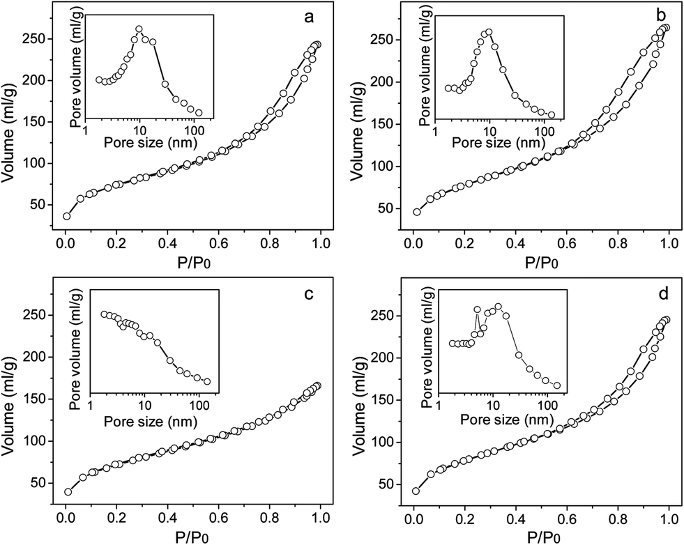 | ||
| Fig. 4 Nitrogen adsorption–desorption isotherms and pore size distribution of the different catalysts: CoOx/SiO2-C (a), CoOx/SiO2-PO (b), Au/CoOx/SiO2-C (c) and Au/CoOx/SiO2-PO (d). | ||
According to the Brunauer classification standard, both of the two supports display the typical Langmuir type-IV isotherm. In the low-pressure region, the adsorption amount rises with the increment in relative pressure; then intensely increases with the further increase of pressure after P/P0 reaching 0.6 due to capillary condensation20 whilst the desorption procedure is irreversible from the adsorption procedure. The rapid desorption process causes the formation of a hysteresis loop along with the decrease of relative pressure, indicating the existence of mesopores. The specific surface areas of the two samples are calculated from the BET equation. The surface area of CoOx/SiO2-C (251.5 m2 g−1) is slightly lower than that of CoOx/SiO2-PO (265.3 m2 g−1). The relative pressure corresponding to the closing of the hysteresis loop reflects the mesopore distribution. That is, for the N2 adsorption–desorption isotherm the material with a narrower size mesopore distribution is going to display a larger distance between upper and lower closing points of the hysteresis loop. Directly from the N2 adsorption–desorption isotherms, the CoOx/SiO2-PO sample under O2 plasma treatment shows a more uniform size distribution with an average pore size of about 10 nm, whereas the CoOx/SiO2-C sample displays a broad size distribution with a peak maximum around 10 nm with a shoulder at 18.2 nm.
Despite decreasing the opening of the hysteresis loop, the gold loading does not vary the isotherm obviously, as shown in Fig. 4c and 4d. The two supported gold samples also display a typical Langmuir type-IV isotherm, indicating that the related materials possess a mesoporous structure. Unlike the H2-type of hysteresis loops over CoOx/SiO2 and Au/CoOx/SiO2-PO, related to the ink-bottle-like pores, the hysteresis loop of Au/CoOx/SiO2-C is a classic H4-type, corresponding to the uniform and slit-shaped porous structure. However, the surface area of Au/CoOx/SiO2-PO gently decreases to 252.1 m2 g−1 compared with the CoOx/SiO2-PO (265.3 m2 g−1), suggesting that the O2 plasma treatment barely changes the porous structure of the different samples. By contrast, the surface area of Au/CoOx/SiO2-C is reduced to 206.2 m2 g−1 after gold loading, illustrating that the structure of the material may transform after the loading. Besides, a great portion of smaller pores appeared in the Au/CoOx/SiO2-C sample with gold loading, which should be caused by the blocking of the gold nanoparticles into the mesoporous structure.
The SEM images of four typical samples are shown in Fig. 5. The contrast in the SEM images (Fig. 5a and 5b) highlights the location of the CoOx particles (white spots) and silica (the gray background). It can be seen obviously that the surface of silica in CoOx/SiO2-C is covered with heterogeneous CoOx particles. By contrast, more uniform particles can be found on the surface of CoOx/SiO2-PO with plasma treatment under O2 atmosphere. After the gold loading and calcination, the morphology of the Au/CoOx/SiO2-C sample seems different. The gold species may spread on the surface of the support, giving a fluffy appearance to the surface. The gold loading procedure may also induce the blocking of mesopores in this sample, as revealed by Fig. 4a and 4c, due to the partial covering of gold particles. However, the Au/CoOx/SiO2-PO displays a totally different morphology, with flocculent morphology and a developed porous structure.
 | ||
| Fig. 5 SEM patterns of the typical catalysts: CoOx/SiO2-C (a), CoOx/SiO2-PO (b), Au/CoOx/SiO2-C (c), and Au/CoOx/SiO2-PO (d). | ||
Transmission electrom microscope (TEM) images of the supported gold nanoparticles are illustrated in Fig. 6. The gold nanoparticles are visualized as black spots. The gold particles of Au/CoOx/SiO2-C are heterogeneous and around 3–5 nm. The O2 plasma-treated gold nanoparticles in the Au/CoOx/SiO2-PO sample are highly distributed on the surface of the support with sizes of only around 1–3 nm. As it is mentioned previously, only gold nanoparticles small enough to displace the macroscopic properties could possess efficient activity for CO oxidation.21,22 The sizes of the supported gold nanoparticles under different treatments all step into the nano-scale >5 nm, which are able to display reasonable low-temperature CO oxidation activity.
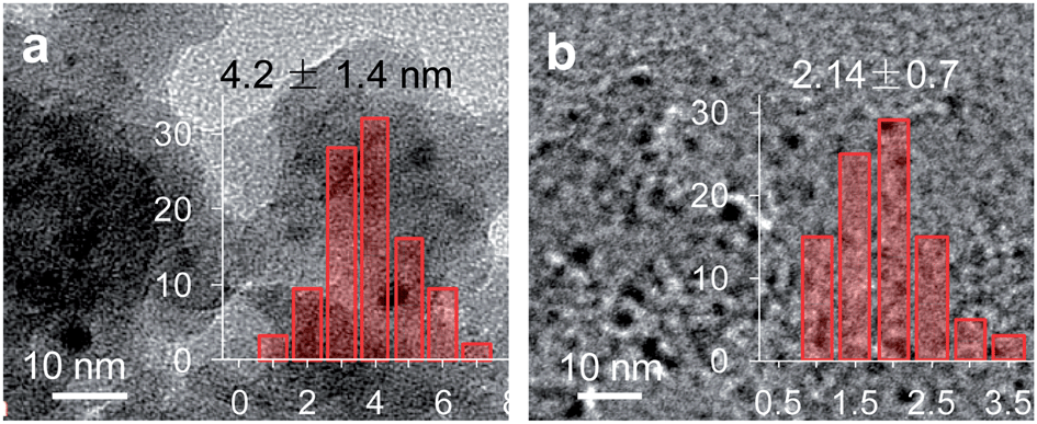 | ||
| Fig. 6 TEM patterns and size distributions of supported gold catalysts: Au/CoOx/SiO2-C (a) and Au/CoOx/SiO2-PO (b). | ||
The above results on the morphologies of the samples under different treatments demonstrate the efficiency of plasma for modifying the available contact surface, promoting the development of porosity, and preventing the pores from being blocked. These superiorities in turn provide the chance to improve the reactant adsorption/dissociation and reaction rate acceleration during CO oxidation.
3.4 Chemical composition and property of catalysts
The characteristics of molecular structures can be reflected by the wavelength and intensity of the absorption bands in the FT-IR spectrum. Here in this case, the FT-IR spectrum can be applied for identifying the composition and chemical groups in the material of interest. In order to analyze the fine chemical structure of different samples, the FT-IR spectra of silica doped with CoOx before and after special treatment and their supported gold catalysts are studied, as shown in Fig. 7. The fresh CoOx/SiO2 before calcination possesses multiple absorption peaks. The peaks around 460 cm−1 and 800 cm−1 can be ascribed to the bending vibration of O–Si–O and Si–O–Si, respectively. There is no observation of the Si–O–Si stretching vibration that should be around 1100 cm−1 due to the covering effect of the adjacent absorption peaks. The shoulder peak located around 946 cm−1 is assigned to the non-bonded Si–O surrounding silica.22 The symmetric stretching vibration of N![[double bond, length as m-dash]](https://www.rsc.org/images/entities/char_e001.gif) O in the nitrate compound is around 1390 cm−1, and the obvious absorption peak at 1640 cm−1 should be due to the water species in the samples.
O in the nitrate compound is around 1390 cm−1, and the obvious absorption peak at 1640 cm−1 should be due to the water species in the samples.
 | ||
| Fig. 7 FT-IR patterns of various catalysts: CoOx/SiO2 (a), CoOx/SiO2-C (b), CoOx/SiO2-PO (c), Au/CoOx/SiO2-C (d), and Au/CoOx/SiO2-PO (e). | ||
The IR spectra of the CoOx/SiO2-C and CoOx/SiO2-PO samples display additional absorption peaks at 568 and 667 cm−1, corresponding to the stretching vibration of the metal–oxygen bond, which is the characteristic absorption peak of Co3O4 spinel. The former peak around 568 cm−1 results from the Co2+–O vibration.23 In addition, the NO stretching vibration (1390 cm−1) in the CoOx/SiO2-C sample disappears, indicating the complete decomposition of the nitrate precursor. However, the weak absorption peak at 1390 cm−1 remains in the CoOx/SiO2-PO sample treated by plasma. In fact, different from CoOx/SiO2-C, there is no further calcination of the CoOx/SiO2-PO after plasma treatment. Unlike the high-temperature calcination that is able to decompose the precursor entirely, the plasma treatment proceeding under gentle conditions may retain some residual nitrate species.11 After the gold loading, the absorption peaks of the silica species and Co3O4 spinel of both Au/CoOx/SiO2-C and Au/CoOx/SiO2-PO are weakened. On the other hand, the samples with gold loading display a very weak water absorption peak (1640 cm−1), suggesting the better water-resistance ability.
The XRD spectra of different samples are profiled in Fig. 8. The broad diffraction peak that appears in all of the samples at 22° is ascribed to the amorphous SiO2 phase (JCPDS #27-0605). The diffraction peaks located at around 32, 36, 44, 59, and 66° in CoOx/SiO2-C should correspond to the surface Co3O4 species (JCPDS #74-2120). The intense and sharp diffraction peaks indicate the existence of large crystallized CoOx particles. In the plasma-treated CoOx/SiO2-PO sample, the Co3O4 diffraction peaks are largely weakened and broadened, resulting from the high dispersion of CoOx species in these samples.7 The dispersed Co3O4 particles provide the opportunity for exposing more active sites, and enable better performance for reactions such as CO oxidation.
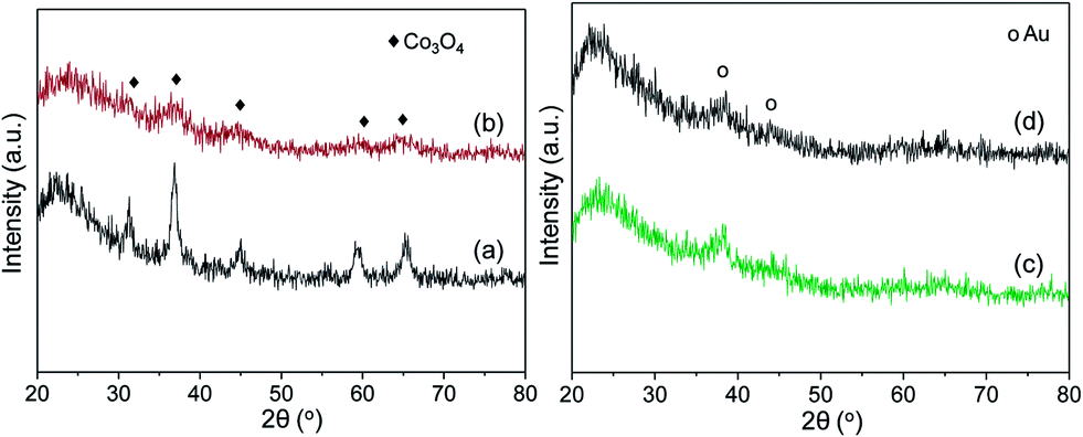 | ||
| Fig. 8 XRD patterns of samples before and after gold loading: CoOx/SiO2-C (a), and CoOx/SiO2-PO (b), Au/CoOx/SiO2-C (c), and Au/CoOx/SiO2-PO (d). | ||
The XRD profiles over gold catalysts under different treatments are shown in the right image of Fig. 8. It can be seen again that the gold loading does not lead to a serious change in the structure. Both the diffraction peaks of amorphous SiO2 around 22° and metallic gold at around 38 and 45° (JCPDS #65-8601) can be observed from the XRD profiles. None of the samples with gold loading present peaks corresponding to Co3O4 species, which may be caused by the redispersion of CoOx species after gold loading.
The Co 2p XPS spectra over several typical samples are displayed in Fig. 9. The peaks with a binding energy of around 781.0 and 796.0 eV can be assigned to Co 2p3/2 and Co 2p1/2 peaks, respectively, with the satellite peak around 786.0 eV. Compared to traditional calcined CoOx/SiO2-C, the binding energy of the CoOx/SiO2-PO sample shifts slightly to higher region.24,25 Although Co2+ and Co3+ possess corresponding binding energies around 780.9–781.4 eV and 779.7–779.9 eV,24 it is still difficult to distinguish the main peak from CoO and the Co3O4 phase due to the very narrow distance. Combining with the results from XRD, the Co 2p3/2 peak with a binding energy around 780.5 eV is inferred as a combination of two overlapped peaks. The corresponding Co 2p XPS profiles of the Au/CoOx/SiO2-C and Au/CoOx/SiO2-PO samples are also shown in Fig. 9. The binding energy of Co 2p3/2 around 780.7 eV suggests the existence of Co3O4 spinel in both catalysts with gold loading.
 | ||
| Fig. 9 Co 2p XPS patterns of two typical CoOx/SiO2 samples: CoOx/SiO2-C (a) and CoOx/SiO2-PO (b), Au/CoOx/SiO2-C (c), and Au/CoOx/SiO2-PO (d). | ||
Furthermore, the CoOx/SiO2-PO shows a larger area peak for Co 2p than does CoOx/SiO2-C, indicating the higher amounts of CoOx species on the surface after plasma treatment (Table 2). This result, from another point of view, evidences the fact that plasma treatment facilitates the formation of a larger amount of smaller CoOx particles. After gold loading, the Co3O4 spinel can be detected in both the Au/CoOx/SiO2-C and Au/CoOx/SiO2-PO samples from the XPS spectra (not shown).
| Catalyst | Surface composition (%) | Intensity ratio | ||
|---|---|---|---|---|
| Co | Si | O | Co/Si (10−1) | |
| CoOx/SiO2-C | 1.88 | 25.92 | 72.20 | 0.73 |
| CoOx/SiO2-PO | 4.11 | 24.82 | 71.07 | 1.66 |
The Au 4f spectra of the above two gold catalysts are presented in Fig. 10. It was reported by Chen et al.26 that the binding energy of the Au 4f7/2 and 4f5/2 of metallic Au0 should appear at around 84.0 and 87.7 eV, respectively, whereas peaks at around 86.0 and 89.6 eV are due to the oxidized gold species (Au3+). Directly from Fig. 10, it can be seen that Au0 acts as the main gold species in both catalysts. There is no clear observation of oxidized gold species in the samples, suggesting that there is no such kind of species or that only a trace amount exists (due to the fact that a very small amount of gold species may be reduced during the XPS measurement). Generally speaking, the shifting of binding energy in the supported gold nanoparticles can be related to the sizes of the gold nanoparticles. Lim et al.27 applied STM (scanning tunneling microscopy) and XPS techniques and discovered that the binding energy of Au 4f shifted 0.8 eV to a higher value along with the decreased particle size. Compared with Au/CoOx/SiO2-C, the Au 4f 7/2 binding energy of Au/CoOx/SiO2-PO increases by about 0.5 eV, which can be viewed as an indication of the smaller particle sizes in the plasma-treated Au/CoOx/SiO2-PO catalysts. This conclusion is in accordance with the results from TEM and XRD experiments.
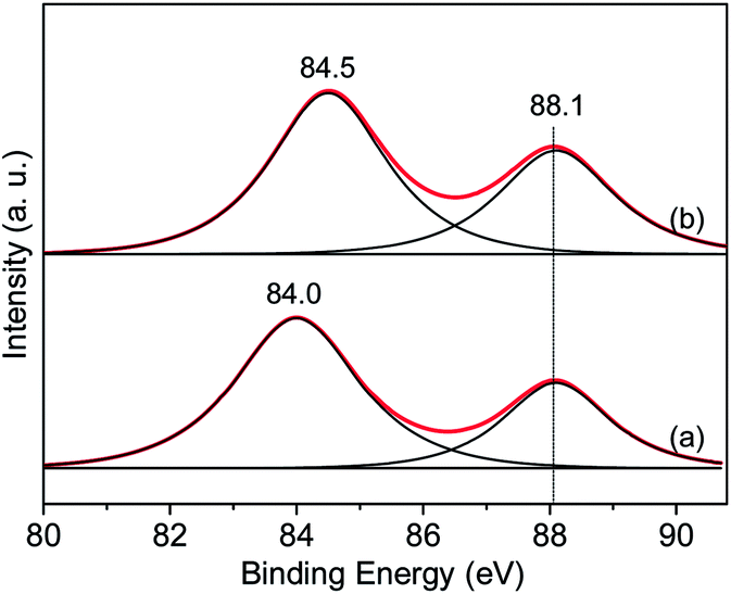 | ||
| Fig. 10 Au 4f XPS patterns of two typical Au/CoOx/SiO2 catalysts: Au/CoOx/SiO2-C (a) and Au/CoOx/SiO2-PO (b). | ||
4. Conclusions
In this work, the CoOx-doped silica was used as a carrier for gold nanoparticles. The impact of plasma treatment under O2 atmosphere over both the carrier and supported gold nanoparticles was discussed in detail. The O2 plasma-treated sample displayed superior activity and stability for CO oxidation. By analyzing the microstructures, morphologies, and chemical compositions of typical samples, the enhancement of the plasma treatment and how it works were exposed in detail. The following conclusions can be obtained.• The variation of morphologies of plasma-treated samples showed the efficiency of plasma treatment for modifying the available contact surface, promoting porosity development, and preventing the pores from being blocked.
• Only metallic Au0 species exist in the supported gold catalysts. The gold nanoparticles in the plasma-treated samples are smaller and homogeneous, which are also highly dispersed on the surface of support.
• The O2 plasma treatment is helpful for enhancing the redox properties of materials, which modifies the synergy between gold and cobalt particles, and in turn improves the redox properties, and facilitate the supplementary circle of active oxygen species during reaction.
Acknowledgements
This work was supported by the Natural Science Foundation of China (20776089) and New Century Excellent Talent Project of China (NCET-05-0783).Notes and references
- Q. Wang, X. K. Wang, Z. F. Chai and W. P. Hu, Chem. Soc. Rev., 2013, 42, 8821–8834 RSC.
- V. E. Fortov, A. V. Ivlev, S. A. Khrapak, A. G. Khrapak and G. E. Morfill, Phys. Rep., 2005, 421, 1–103 CrossRef PubMed.
- N. A. Savastenko, K. Anklam, A. Quade, M. Bruser, A. Schmuhl and V. Bruser, Energy Environ. Sci., 2011, 4, 3461–3472 CAS.
- S. Mahammadunnisa, P. M. K. Reddy and C. Subrahmanyam, RSC Adv., 2014, 4, 4034–4036 RSC.
- K. H. Yu, Z. H. Wen, H. H. Pu, G. H. Lu, Z. Bo, H. Kim, Y. Y. Qian, E. Andrew, S. Mao and J. H. Chen, J. Mater. Chem. A, 2013, 1, 188–193 CAS.
- A. Y. Khodakov, W. Chu and P. Fongarland, Chem. Rev., 2007, 107, 1692–1744 CrossRef CAS PubMed.
- H. Y. Xu, W. Chu, L. M. Shi, S. Y. Deng and H. Zhang, React. Kinet. Catal. Lett., 2009, 97, 243–247 CrossRef CAS PubMed.
- W. Chu, L. N. Wang, P. A. Chernavskii and A. Y. Khodakov, Angew. Chem., Int. Ed., 2008, 47, 5052–5055 CrossRef CAS PubMed.
- D. Van Thanh, L. J. Li, C. W. Chu, P. J. Yen and K. H. Wei, RSC Adv., 2014, 4, 6946–6949 RSC.
- C. J. Liu, K. L. Yu, Y. P. Zhang, X. L. Zhu, F. He and B. Eliasson, Appl. Catal., B, 2004, 47, 95–100 CrossRef CAS PubMed.
- H. Y. Xu, W. Chu, L. M. Shi, H. Mang and J. Zhou, Acta Phys.–Chim. Sin., 2008, 24, 1085–1089 CAS.
- H. Y. Xu, W. Chu, J. J. Luo and T. Zhang, Chem. Eng. J., 2011, 170, 419–423 CrossRef CAS PubMed.
- H. Y. Xu, W. Chu, J. J. Luo and M. Liu, Catal. Commun., 2010, 11, 812–815 CrossRef CAS PubMed.
- Y. Azizi, C. Petit and V. Pitchon, J. Catal., 2010, 269, 26–32 CrossRef CAS PubMed.
- S. Belin, C. L. Bracey, V. Briois, P. R. Ellis, G. J. Hutchings, T. I. Hyde and G. Sankar, Catal. Sci. Technol., 2013, 3, 2944–2957 CAS.
- M. A. Al-Daous, A. A. Manda and H. Hattori, J. Mol. Catal. A: Chem., 2012, 363–364, 512–520 CrossRef CAS PubMed.
- J. J. Luo, H. Y. Xu, Y. F. Liu, W. Chu, C. F. Jiang and X. S. Zhao, Appl. Catal., A, 2012, 423–424, 121–129 CrossRef CAS PubMed.
- J. Luo, Y. Liu, W. Sun, C. Jiang, H. Xie and W. Chu, Fuel, 2014, 123, 241–247 CrossRef CAS PubMed.
- K. L. Yu, C. J. Liu, Q. Xia, J. J. Zou and B. Eliasson, Prog. Chem., 2002, 14, 456–461 CAS.
- G. Mistura, A. Pozzato, G. Grenci, L. Bruschi and M. Tormen, Nat. Commun., 2013, 4 Search PubMed.
- G. C. Bond and D. T. Thompson, Appl. Catal., A, 2006, 302, 1–4 CrossRef CAS PubMed.
- J. J. Luo, W. Chu, S. Sall and C. Petit, Colloids Surf., A, 2013, 425, 83–91 CrossRef CAS PubMed.
- H. Qi, J. Ma and P. Z. Wong, Colloids Surf., A, 2002, 206, 401–407 CrossRef CAS.
- C. S. Sharma, R. Awasthi, R. N. Singh and A. S. K. Sinha, Phys. Chem. Chem. Phys., 2013, 15, 20333–20344 RSC.
- R. Moreno-Tost, E. R. Castellón and A. Jiménez-López, J. Mol. Catal. A: Chem., 2006, 248, 126–134 CrossRef CAS PubMed.
- C. T. Chang, B. J. Liaw, C. T. Huang and Y. Z. Chen, Appl. Catal., A, 2007, 332, 216–224 CrossRef CAS PubMed.
- D. C. Lim, I. Lopez-Salido, R. Dietsche, M. Bubek and Y. D. Kim, Angew. Chem., Int. Ed., 2006, 45, 2413–2415 CrossRef CAS PubMed.
| This journal is © The Royal Society of Chemistry 2014 |