High gas barrier imparted by similarly charged multilayers in nanobrick wall thin films†
D. A. Hagena,
C. Boxb,
S. Greenleea,
F. Xianga,
O. Regev*c and
J. C. Grunlan*abde
aDepartment of Mechanical Engineering, Texas A&M University, College Station, Texas 77843, USA. E-mail: jgrunlan@tamu.edu
bDepartment of Chemical Engineering, Texas A&M University, College Station, Texas 77843, USA
cDepartment of Chemical Engineering, Ben Gurion University of the Negev, 84105 Beer Sheva, Israel
dDepartment of Materials Science and Engineering, Texas A&M University, College Station, Texas 77843, USA
eDepartment of Chemistry, Texas A&M University, College Station, Texas 77843, USA
First published on 7th April 2014
Abstract
Super oxygen barrier trilayer thin films have been deposited using two successive anionic layers of clay and polymer following every cationic polymer layer during layer-by-layer assembly. Polymer–clay bilayer films show good oxygen barrier properties due to a nanobrick wall structure consisting of clay nanoplatelets within the polymeric mortar. It is shown here that adding an anionic polymer layer reduces free volume of the film by filling in gaps of the similarly charged clay layer and increases the barrier performance over the bilayer configuration by at least one order of magnitude. Highly aligned platelets with some non-continuous clay stacks were imaged at nanometer resolution within the microtomed LbL thin film. The super gas barrier, transparent nanocoatings obtained are useful for a variety of food, pressurized, and flexible electronics packaging applications.
Introduction
There is significant interest in transparent, flexible thin films that exhibit good oxygen barrier properties for applications such as food packaging, flexible electronics, and pressurized bladders.1–3 SiOx and AlxOy films exhibit good gas barrier properties, but they have a tendency to crack upon flexing and require vacuum processing environments.4,5 Thin film nanocomposites constructed using layer-by-layer (LbL) assembly are a good alternative to these inorganic layers due to their tailorability, robustness, and simple processing environments.6 In addition to being excellent gas barriers,7–12 these films have also been prepared for pharmaceutical,13–15 superhydrophobic,16,17 antimicrobial,18 anti-flammable,19,20 and electrically conductive21,22 applications. This wide range of properties is made possible by the large variety of components that can be employed in LbL assembly: polymers,23 nanoparticles,24 quantum dots,25 and biological molecules.26 Beyond the constituents used, the properties of the composite films can be further tuned by varying molecular weight,27 deposition time, concentration, pH, ionic strength,28 and temperature.29The LbL process has been used to create very good barriers using bilayer (BL) and quadlayer (QL) systems that utilize impermeable nanoplatelets (e.g., clay and graphene oxide), each approximately 1 nm thick with aspect ratios up to several thousand, to create an extremely tortuous pathway for diffusion of gas molecules.7–12 The water based nature of the layer-by-layer process allows for partially exfoliated and oriented clay platelets to be deposited every cycle, generating a nanobrick wall structure. This structure provides superior properties over bulk composites where aggregation and random orientation lead to increased opacity and greater gas permeability.9 The traditional method of constructing LbL thin films involves alternately depositing layers from oppositely charged solutions.6 One disadvantage of this approach is the incomplete coverage of a surface due to the rigidity of clay platelets. In the present study, we show that succeeding the anionic clay layer with a similarly charged polymer layer significantly improves the gas barrier by filling in the gaps between clay platelets of the same layer. A trilayer (TL) system consisting of the cationic polyethylenimine (PEI), anionic montmorillonite clay (MMT), and anionic poly(acrylic acid) (PAA) is used to create super gas barrier nanobrick walls. A trilayer system, similar to that examined here has recently been studied to combine the exponential growth of all polymer systems with the flame retardant behaviour of montmorillonite clay.30 Our focus here, however, is on gas barrier properties. At comparable thickness to PEI/MMT bilayers, these PEI/MMT/PAA trilayers achieve an oxygen transmission rate that is more than an order of magnitude lower.
Experimental
Materials
Natural sodium montmorillonite clay (MMT, trade name Cloisite NA+) provided by Southern Clay Products, Inc. (Gonzales, TX), was dispersed as a 1 wt% suspension in deionized (DI) water by rolling solutions in bottles overnight. MMT platelets have a reported density of 2.86 g cm−3, diameter ranging from 10–1000 nm, and thickness of 1 nm.31 Poly(acrylic acid) (PAA) (Mw = 100![[thin space (1/6-em)]](https://www.rsc.org/images/entities/char_2009.gif) 000 g mol−1, ρ = 1.20 g cm−3), purchased from Sigma Aldrich (Milwaukee, WI), was used as a 0.2 wt% solution in DI water. Branched polyethylenimine (PEI) (Mw = 25000 g mol−1, ρ = 1.10 g cm−3) was also purchased from Sigma-Aldrich and used as a 0.1 wt% DI water solution.
000 g mol−1, ρ = 1.20 g cm−3), purchased from Sigma Aldrich (Milwaukee, WI), was used as a 0.2 wt% solution in DI water. Branched polyethylenimine (PEI) (Mw = 25000 g mol−1, ρ = 1.10 g cm−3) was also purchased from Sigma-Aldrich and used as a 0.1 wt% DI water solution.
Substrates
Poly(ethylene terephthalate) (PET) film, with a thickness of 179 μm (trade name ST505, produced by Dupont-Teijin), was purchased from Tekra (New Berlin, WI) and used as the substrate for oxygen transmission rate (OTR) testing and transmission electron microscopy (TEM). This PET film has an OTR of approximately 8.6 cm3 per m2 per day per atm under dry conditions. Polished silicon wafers were purchased from University Wafer (South Boston, MA) and were used as substrates for ellipsometry and atomic force microscopy. They were treated with piranha solution in a 3:1 mass ratio of 30% hydrogen peroxide to 99% sulfuric acid and stored in deionized (DI) water [Caution! Piranha solution should be handled with extreme caution!]. Silicon wafers were rinsed with DI water, acetone, and then DI water immediately before use. Prior to deposition, PET substrates were rinsed with DI water, methanol, and then DI water, followed by treatment of each side of the substrate using a BD-20C Corona Treater (Electro-Technic Products, Inc., Chicago) to ensure an adequate negative surface charge before coating.
Layer-by-layer assembly
Each substrate was dipped into the cationic 0.1 wt% PEI solution (adjusted to pH 10.0 using 1 M HCl) for 5 minutes. After this, and every subsequent dip, the substrate was rinsed with DI water and dried with filtered air. The substrate was then dipped into the anionic MMT suspension (unaltered pH of ∼9.7) for five minutes, which completed a single bilayer (BL) dipping cycle, as illustrated in Fig. 1. When depositing trilayer films, the substrate was dipped into the anionic PAA solution (adjusted to pH 4.0 using 1 M NaOH) for 1 minute to complete a TL cycle. All subsequent dips were 1 minute, following the sequence described above. After the final rinsing and air drying, the films deposited on PET were dried in an oven at 70 °C for 15 min. | ||
| Fig. 1 Illustrations of (a) the LbL dipping process and (b) nanobrick wall structures built from alternate adsorption of PEI (green) and MMT (orange) for the BL system (top) and PEI, MMT, and PAA (blue) for the TL system (bottom). | ||
Characterization
Thickness measurements were taken as a function of layers deposited using an α-SE spectroscopic ellipsometer (J.A. Woodlam Co, Inc., Lincoln, NE). Mass deposition onto Ti/Au plated quartz crystals was measured using a Research Quartz Crystal Microbalance (QCM) (Maxtek Inc., Cypress, CA). Density was calculated by dividing the mass/area obtained with QCM by the film thickness. Data for clay mass deposition were taken between 10 and 20 cycles to avoid substrate effects. Visible light was measured using a USB2000-UV-Vis Spectrometer (Ocean Optics, Dunedin, FL). Atomic force microscopy data (AFM) was acquired using a Dimension Icon AFM (Bruker, Billerica, MA) in tapping mode with an HQ:NSC35/Al BS probe (Mikromasch, Lady's Island, SC). Root mean square roughness (rms) measurements were taken from a 20 μm × 20 μm area. OTR testing was performed according to ASTM D-3985 specifications by MOCON (Minneapolis, MN) using an Oxtran 2/21 ML instrument at testing conditions of 23 °C and 0% RH. Samples for TEM were prepared by embedding the film in Epofix (EMS, Hatfield, PA) resin overnight and cutting sections, using an Ultra 45° diamond knife (Diatome, Hatfield, PA), onto 300 mesh copper grids. TEM micrographs of the thin film cross sections (∼90 nm thick) were imaged using a Tecnai G2 F20 (FEI, Hillsboro, OR) at an accelerating voltage of 200 kV.Results and discussion
Film growth
Fig. 2 compares the thickness of PEI/MMT bilayers and PEI/MMT/PAA trilayers. The polymer/clay bilayers increase in thickness linearly at 4.0 nm/BL (Fig. 2(a)). When PAA is employed as a third layer in each deposition cycle, the growth rate increases slightly to 5.2 nm/TL for two reasons. PAA deposits onto the exposed areas of PEI between MMT platelets via electrostatic attraction. Any exposed PEI is at a more highly charged state in the PAA solution (pH 4) than it was in the MMT solution (pH 9.7), aiding in the attraction of PAA. Secondly, PAA carbonyls can hydrogen bond with MMT hydroxyl groups at low pH due to the minimal electrostatic repulsion between weakly-charged PAA chains and MMT platelets.30,32,33 PAA fills in the gaps of the MMT layer which provides a more uniform, negatively charged surface on which the following layer of PEI can deposit, which contributes to the increased thickness of the trilayer system.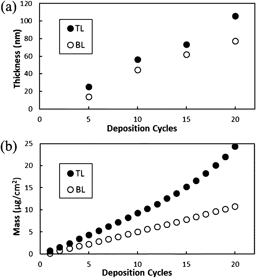 | ||
| Fig. 2 (a) Thickness and (b) mass of PEI/MMT bilayer and PEI/MMT/PAA trilayer systems as a function of deposition cycles. | ||
The mass of the trilayer film per cycle is significantly greater than that of the bilayer film (Fig. 2(b)) due to PAA occupying free volume that cannot be filled by the relatively large, rigid clay platelets. This higher packing efficiency for the trilayer system is verified by examining the density of both thin films. After 20 cycles the bilayer system has a density of 1.39 g cm−3, compared to a density of 2.30 g cm−3 for the trilayer system. In addition to filling in voids between MMT platelets, PAA can diffuse into underlying PEI layers via an in and out diffusion mechanism that is commonly observed in exponentially growing thin films.27,34,35 A previous study showed that a 10 BL film of PEI/PAA has a thickness greater than 1 μm and a mass of approximately 140 μg cm−2 due to the large amount of diffusion of each of the polymers into the film.11 The thickness and mass of this all-polymer system are more than an order magnitude greater than that of the clay filled TL system. This is because PAA cannot diffuse directly through the MMT platelets, which inhibit the exponential growth observed in the all polymer system.8 However, the exposed areas of PEI between clay platelets allow some diffusion of PAA into the film which could increase the mass of the system. The subsequent layer of PEI not only has a smooth anionic surface of MMT and PAA on which to deposit, but also has soft areas of PAA into which it can diffuse, whereas in the PEI/MMT bilayer, it is only attracted to the MMT covered surface. In the previous study of this trilayer system (for flame retardant properties), in which a 0.2 wt% solution of clay was used, the mass of 10 TL was approximately five times the mass of the 10 TL system measured here. This is presumably due to a lower number of clay platelets being deposited and increased diffusion of PAA into the underlying PEI. In the present study, there is an average of 65% more clay deposited in the TL system per cycle than in the BL system (0.84 μg cm−2 and 0.51 μg cm−2 respectively, Fig. S1†) which means there is better lateral packing of clay platelets and/or more platelets (or stacks) deposited on top of each other every layer. This is most likely a result of a more uniform PEI layer that deposits onto the MMT/PAA surface, where the bilayer system may have gaps in the coverage resulting in a lower net attraction of MMT platelets (illustrated schematically in Fig. 1(b)).
Interestingly, if the order of MMT and PAA is switched (e.g. PEI/PAA/MMT) the film's morphology changes completely. The thickness of this reversed trilayer system is the same as that of PEI/PAA, and no additional mass is detected during the MMT deposition. Therefore, we conclude that MMT does not deposit onto a PAA covered surface at the given pH conditions. At the supramolecular level, the PAA–MMT attraction could stem from either electrostatic interaction or hydrogen bonding; given that they are both negatively charged, the electrostatic force is repulsive. PAA, unlike the relatively large MMT platelets, completely covers and uniformly reverses the charge of the PEI covered surface, leaving no exposed PEI to attract MMT.11 Furthermore, hydrogen bonding between PAA and MMT does not occur at the high pH condition (9.7) of the MMT solution due to PAA becoming highly charged.30,32,33 Therefore, MMT platelets are repelled from the surface in the PEI/PAA/MMT coating sequence.
Film morphology
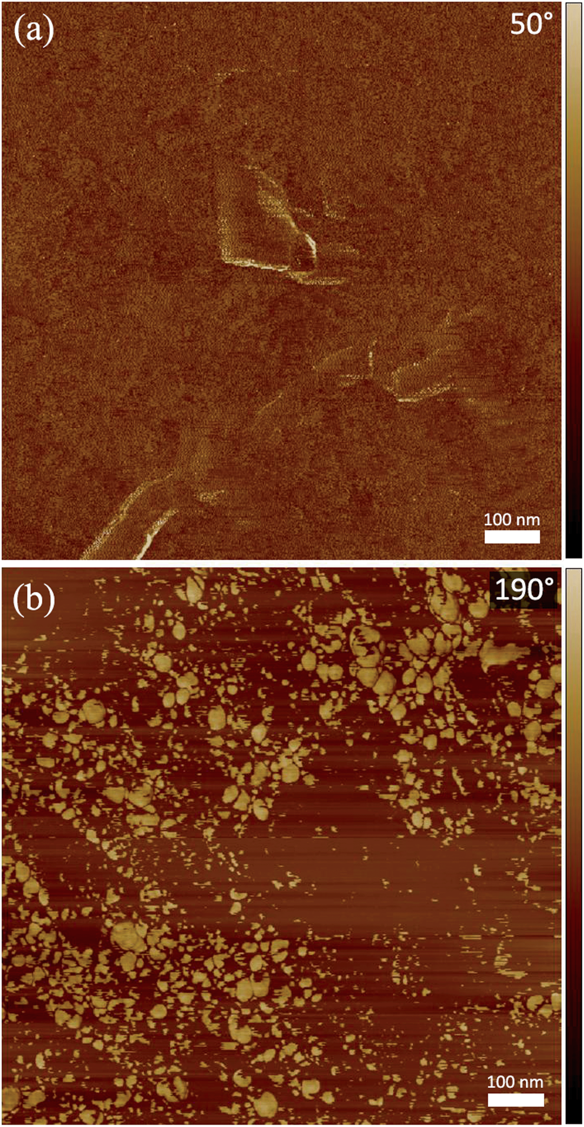
TEM images of a microtomed 20 TL film (Fig. 3(a)–(c)) highlight the high level of ordering of these nanobrick walls. Montmorillonite clay platelets, about 1 nm thick and 100 nm in diameter,31 possess high electron density due to the aluminum, magnesium and silicon atoms that cause them to appear as dark lines in these images. The polymers present (PEI, PAA, supporting PET film, and epoxy support) have much lower electron density and therefore appear brighter in the micrographs. There are many more clay platelets seen (∼45-Fig. 3(a)) through the thickness of the film than there were deposition cycles (20), which demonstrates that each deposition cycle does not deposit only one discrete layer of clay platelets along the surface. It is likely that doublet and triplet stacks of clay platelets are deposited every cycle, due to only partial exfoliation in solution, and the mobility of the successive polymer is high enough to intercalate these stacks on the surface. A stack of 5 MMT platelets is shown (Fig. 3(c), bottom, dashed). The stack is deposited at the bottom of the film with no platelets directly to its left. A second stack of three platelets appears higher in the image and does not align with the surrounding platelets. The average thickness of the 20 TL film as measured from TEM images (94 ± 13 nm (n = 50)) is in good agreement with ellipsometry measurements (Fig. 2(a)). The clay platelet spacing within the film is rather uniform, as demonstrated by the Fourier transform analysis taken from the entire thickness of the image (Fig. 3(a) inset). The TEM images of the bilayer film reveals highly aligned platelets, but also lighter areas between some of the clay platelets indicating gaps in the nanobrick wall structure (Fig. 3(d)). | ||
| Fig. 3 (a) TEM cross section of a 20 PEI/MMT/PAA trilayer film prepared using a microtome and Fourier transform inset. The white rectangle in (a) is shown at higher magnification in (b), and stacks of MMT platelets within the film are shown in (c). (d) Cross section of part of a 20 BL film. | ||
The bilayer film surface is rougher than the trilayer surface (rms roughness values of 19.5 nm and 15.7 nm, respectively from Fig. S2†) due to PAA filling in the gaps between MMT platelets, as illustrated in Fig. 1(b). The surface of a 10 trilayer film was imaged before and after the final PAA deposition to demonstrate the partial deposition of PAA onto a the MMT surface. AFM phase images represent the phase shift (delay) of the cantilever compared to its free oscillation. This delay can be caused by soft or viscoelastic materials,36 such as PAA, that appears as lighter areas in Fig. 4. There is a stark contrast between the phase images between the MMT covered surface and the MMT/PAA covered surface (Fig. 4), which should not be confused with topography (the surface is in fact slightly rougher before the PAA deposition). There are regions where the PAA deposition is less concentrated, which could be areas of greater clay platelet coverage and PAA is only attracted to the surface via hydrogen bonding.
 | ||
| Fig. 4 AFM phase images of 10 TL of PEI/MMT/PAA (a) before the final layer of PAA is deposited and (b) with the final layer of PAA deposited. | ||
It should be noted that a 20 TL film, with a thickness of 106 nm, has an average light transmission of 95% across the visible light spectrum (390–750 nm). This high level of transparency is a key requirement for electronic display encapsulation and is desirable for many food packaging applications.3 It is the high level of orientation of the clay within the composite film that makes this exceptional transparency possible.
Gas barrier properties
The difference in gas barrier properties between the bilayer and trilayer nanobrick walls is more pronounced than the differences in thickness and mass (Fig. 2). Oxygen transmission rates for both systems are summarized in Fig. 5. While 5 BL shows only a small reduction in oxygen transmission rate over the bare PET support (OTR is 7.3 and 8.5 cm3 per m2 per day, respectively), the 5 TL thin film shows nearly a factor of three improvement. Furthermore, a 10 TL film has lower OTR than 20 BL despite having half as many clay depositions. 20 TL is at the detection limit of commercial equipment (0.005 cm3 per m2 per day), a 1600× improvement over 179 μm PET (8.6 cm3 per m2 per day per atm). The OTR of 20 TL is nearly one order of magnitude lower than that of 20 BL. This improvement comes from the inclusion of more clay platelets per deposition cycle and also from the free volume reduction discussed previously, which slows the diffusion of oxygen molecules through the film. Having more platelets deposited every cycle provides smaller gaps between platelets on the same plane and/or more platelets to diffuse around vertically. Both of these scenarios create a more tortuous path for oxygen molecules, leading to better barrier performance. The permeability of the 20 TL film is extremely low (1.21 × 10⁻²¹ (cm3 cm per cm2 per s per Pa) in Table S1†) at a thickness of only 105.8 nm. Thin film permeability is decoupled from the substrate permeability using a previously described method.37 | ||
| Fig. 5 Oxygen transmission rates for PEI/MMT bilayers and PEI/MMT/PAA trilayers as a function of bilayer or trilayer sequences deposited. | ||
Conclusions
Here it was shown that the addition of a polymer layer with similar charge as clay fills uncovered spaces in the nanobrick wall and dramatically increases oxygen barrier properties by reducing the free volume. The exceptionally high oxygen barrier exhibited, coupled with high transparency, ease of fabrication, and mechanical flexibility, makes these films well suited for pressurized systems, food packaging, and flexible electronics.Acknowledgements
The authors acknowledge The Dow Chemical Company and the Texas A&M Engineering Experiment Station for financial support of this work. Special thanks are paid to Eddy Garcia-Meitin at The Dow Chemical Company for guidance in TEM sample preparation.Notes and references
- G. L. Graff, P. E. Burrows, R. E. Williford and R. F. Praino, in Flexible Flat Panel Displays, John Wiley & Sons, Ltd, Chichester, UK, 2005, pp. 57–77 Search PubMed.
- M. Bowles and L. Jianjun, 8th International Conference on Computing and Networking Technology (ICCNT), 2012 Search PubMed.
- K. L. Yam and D. S. Lee, Emerging food packaging technologies: Principles and practice, Woodhead Publishing, Cambridge, UK, 2012 Search PubMed.
- Y. Leterrier, Prog. Mater. Sci., 2003, 48, 1–55 CrossRef CAS.
- J. D. Affinito, M. E. Gross, C. A. Coronado, G. L. Graff, E. N. Greenwell and P. M. Martin, Thin Solid Films, 1996, 290, 63–67 CrossRef.
- G. Decher and J. B. Schlenoff, Multilayer Thin Films, Wiley-VCH Verlag GmbH & Co. KGaA, Weinheim, Germany, 2012 Search PubMed.
- M. A. Priolo, D. Gamboa and J. C. Grunlan, ACS Appl. Mater. Interfaces, 2010, 2, 312–320 CAS.
- M. A. Priolo, D. Gamboa, K. M. Holder and J. C. Grunlan, Nano Lett., 2010, 10, 4970–4974 CrossRef CAS PubMed.
- A. J. Svagan, A. Åkesson, M. Cárdenas, S. Bulut, J. C. Knudsen, J. Risbo and D. Plackett, Biomacromolecules, 2012, 13, 397–405 CrossRef CAS PubMed.
- C. Ratanatawanate, M. Perez, B. E. Gnade and K. J. Balkus Jr, Mater. Lett., 2012, 66, 242–245 CrossRef CAS PubMed.
- Y.-H. Yang, M. Haile, Y. T. Park, F. A. Malek and J. C. Grunlan, Macromolecules, 2011, 44, 1450–1459 CrossRef CAS.
- Y.-H. Yang, L. Bolling, M. A. Priolo and J. C. Grunlan, Adv. Mater., 2013, 25, 503–508 CrossRef CAS PubMed.
- J. B. Gilbert, J. S. O'Brien, H. S. Suresh, R. E. Cohen and M. F. Rubner, Adv. Mater., 2013, 25, 5948–5952 CrossRef CAS PubMed.
- J. Hong, L. Alvarez, N. Shah, Y. Cho, B.-S. Kim, L. Griffith, K. Char and P. Hammond, Drug Delivery Transl. Res., 2012, 2, 375–383 CrossRef CAS.
- J. Cui, Y. Yan, Y. Wang and F. Caruso, Adv. Funct. Mater., 2012, 22, 4844 CrossRef CAS.
- L. Zhai, F. C. Cebeci, R. E. Cohen and M. F. Rubner, Nano Lett., 2004, 4, 1349–1353 CrossRef CAS.
- L. Zhang and J. Q. Sun, Macromolecules, 2010, 43, 2413–2420 CrossRef CAS.
- J. A. Lichter, K. J. Van Vliet and M. F. Rubner, Macromolecules, 2009, 42, 8573–8586 CrossRef CAS.
- G. Laufer, C. Kirkland, A. B. Morgan and J. C. Grunlan, ACS Macro Lett., 2013, 2, 361–365 CrossRef CAS.
- A. A. Cain, C. R. Nolen, Y.-C. Li, R. Davis and J. C. Grunlan, Polym. Degrad. Stab., 2013, 98, 2645–2652 CrossRef CAS PubMed.
- B. S. Shim, J. A. Zhu, E. Jan, K. Critchley and N. A. Kotov, ACS Nano, 2010, 4, 3725–3734 CrossRef CAS PubMed.
- C. Huang, N. Grobert, A. A. R. Watt, C. Johnston, A. Crossley, N. P. Young and P. S. Grant, Carbon, 2013, 61, 525–536 CrossRef CAS PubMed.
- E. Kharlampieva, V. Kozlovskaya and S. A. Sukhishvili, Adv. Mater., 2009, 21, 3053–3065 CrossRef CAS.
- P. Kekicheff, G. F. Schneider and G. Decher, Langmuir, 2013, 29, 10713–10726 CrossRef CAS PubMed.
- E. Kharlampieva, V. Kozlovskaya, O. Zavgorodnya, G. D. Lilly, N. A. Kotov and V. V. Tsukruk, Soft Matter, 2010, 6, 800–807 RSC.
- T. Boudou, T. Crouzier, C. Nicolas, K. Ren and C. Picart, Macromol. Biosci., 2011, 11, 77–89 CrossRef CAS PubMed.
- C. Porcel, P. Lavalle, G. Decher, B. Senger, J. C. Voegel and P. Schaaf, Langmuir, 2007, 23, 1898–1904 CrossRef CAS PubMed.
- M. Ferreira and M. F. Rubner, Macromolecules, 1995, 28, 7107–7114 CrossRef CAS.
- Y. Lu, A. Zhuk, L. Xu, X. Liang, E. Kharlampieva and S. Sukhishvili, Soft Matter, 2013, 9, 5464 RSC.
- Y. S. Kim, R. Harris and R. Davis, ACS Macro Lett., 2012, 1, 820–824 CrossRef CAS.
- H. J. Ploehn and C. Y. Liu, Ind. Eng. Chem. Res., 2006, 45, 7025–7034 CrossRef CAS.
- N. H. Tran, G. R. Dennis, A. S. Milev, G. S. K. Kannangara, M. A. Wilson and R. N. Lamb, J. Colloid Interface Sci., 2005, 290, 392–396 CrossRef CAS PubMed.
- J. Billingham, C. Breen and J. Yarwood, Vib. Spectrosc., 1997, 14, 19–34 CrossRef CAS.
- L. Richert, P. Lavalle, E. Payan, X. Z. Shu, G. D. Prestwich, J. F. Stoltz, P. Schaaf, J. C. Voegel and C. Picart, Langmuir, 2004, 20, 448–458 CrossRef CAS.
- C. Picart, P. Lavalle, P. Hubert, F. J. G. Cuisinier, G. Decher, P. Schaaf and J. C. Voegel, Langmuir, 2001, 17, 7414–7424 CrossRef CAS.
- P. W. P. Eaton, Atomic force microscopy, Oxford Univ. Press, Oxford, 2010 Search PubMed.
- L. E. Nielsen, J. Macromol. Sci., Part A: Pure Appl.Chem., 1967, 1, 929–942 CrossRef CAS.
Footnote |
| † Electronic supplementary information (ESI) available: Tabulated oxygen transmission, permeability, and mass deposition data and AFM topography images. See DOI: 10.1039/c4ra01621a |
| This journal is © The Royal Society of Chemistry 2014 |