The role of substrate interactions in the modification of surface forces by self-assembled monolayers

B. W. Ewers and J. D. Batteas *
Department of Chemistry, Texas A&M University, PO Box 30012, College Station, TX 77842-3012, USA. E-mail: batteas@chem.tamu.edu

Received 18th February 2014 , Accepted 26th March 2014

First published on 27th March 2014


Abstract

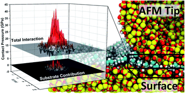
Self-assembled monolayers have been used extensively as surface modifications and model systems for friction and adhesion mitigation on surfaces. From experiment, it is unclear to what extent and under what conditions the substrate plays a role in the modification of these surface forces, but because SAMs are relatively compliant and thin, it is reasonable to assume that the unique frictional characteristics of these monolayers is driven in part by substrate effects. Molecular dynamics simulation and methods developed for analysis of total interaction area, and direct substrate interaction, have been employed to investigate the structure of surface asperity contacts coated with SAMs, examining these interactions and determining what role substrate interactions and other possible dissipation mechanisms are involved in the friction response of SAMs. It was observed that for sparse OTS films, typical of films formed on rough or asperity surfaces, substrate interactions are extensive, leading to increased tribochemistry and strain at sliding interfaces. For densely packed films, it was found that even pressures on the order of a few GPa do not lead to direct substrate interaction, but there is a distinct and localized increase in the compressive strain on the film, indicating the development of new dissipative modes during sliding at high pressures including conformational changes and wear of the films.

Introduction

Over the past 30 years, the self-assembled monolayer has become a mainstay of surface modification.1–3 Their simple chemical structure, ease of application, and high tailorability allow researchers and developers to modify the chemistry of interfaces in well-controlled fashion. An area of relatively recent interest has been the modification of surfaces with SAMs to achieve improved friction response and wear resistance, particularly in applications in Microelectromechanical Systems Devices (MEMS),4–6 where traditional lubrication is not feasible, surface coatings are one of few viable alternatives, and contact forces are relatively small. Traditional, covalently bound SAMs proved relatively ineffective in preventing wear7,8 even at these very small sliding interfaces, but self-healing approaches like vapour phase lubrication with SAMs9 and even simple alcohols10 have met with some success. Furthermore, SAMs provide an excellent platform for investigating dissipative mechanisms at interfaces with adsorbed monolayers as their structure and chemistry is well defined.

The ability of SAMs to modify the surface forces that dictate friction and adhesion at interfaces has been well documented.11,12 To investigate fundamental processes in the dissipation of energy at sliding interfaces, precise control of the geometry and chemistry of the interfaces is required, therefore friction response is best measured using methods where the contact area is either measurable or at least predictable. This is achievable with the Surface Force Apparatus (SFA),13 the Interfacial Force Microscope (IFM),14 or the Atomic Force Microscope (AFM).15 In a vast majority of cases the friction response of sliding interfaces in these experiments is consistent with the laws of single asperity friction,16,17 that is, the friction force is proportional to the contact area:

 
F = τA(1)
where τ is the interfacial shear strength, a measure of the lateral stiffness of the contact. The friction response of SAMs has in many cases been observed to be consistent with the single asperity friction law.18 Many other cases exist of single asperity friction responses consistent with Amonton's law,19–22 wherein friction response is directly proportional to the contact load with no apparent dependence on contact area. Leggett and co-workers have extensively examined the friction response under controlled solvent environments, observing friction consistent with both Amonton's law and single asperity friction laws, depending on the extent of solvation of the SAM interface.23,24 They find that the friction response of SAMs can effectively be understood in terms of a three term friction law25 that is essentially a combination of the single asperity friction law and Amonton's law:
 
F = τA + μL + F0(2)

In addition to the interfacial shear strength, μ is the traditional load dependent term referred to herein as simply the friction coefficient. This term perhaps arises from chemical interactions at the interface, as it has been shown that the number of atomic contacts is proportional to the applied load for non-adhesive contacts.26,27 The Derjaguin offset, F0, has been suggested to be related to the zero-load contact area of the molecular monolayers.28 Because the cohesive forces of SAMs consist of only weak van der Waals interactions, the shear strain is of limited magnitude and spatial extent, thus minimizing shear related dissipation and thereby limiting the interfacial shear strength.29,30 A low interfacial shear strength results in a friction response that is dominated by the load dependent term, and a response consistent with Amonton's law. Alternatively, because the SAM effectively decouples the two sliding interfaces, the contact area may be viewed as only the contact area between the asperity surfaces,25 which for sufficiently low loads may be negligible. This can potentially be manipulated by increasing the adhesion at the interface, which can be achieved by using solvents that do not sufficiently solvate the end-groups of the SAM. The increased molecular interaction at the SAM interface thereby leads to greater shear strength in the contact due to increased coherence of the SAM molecules during sliding or increased mechanical coupling of the interface.

Alternative explanations for this behaviour have been proposed by Szlufarska et al.,31 observing by molecular dynamics simulation of a hard asperity contact that, for a non-adhesive contact, friction and true contact area are proportional to load. This result was obtained by completely neglecting long range van der Waals interactions. Because SAM molecules lack the short range structural rigidity of a solid substrate, even these weak forces will play a significant role in the extent of atomic contact, so though perhaps valid for hard surface contacts, their result is likely not applicable to friction on SAM coatings.

Where the friction of SAMs becomes particularly unclear is at greater applied pressures. Salmeron et al. identified four different friction regimes for octadecyltrichlorosilane (OTS) derived SAMs on mica examined by AFM,32 ranging from elastic dissipation mechanisms at low load to response dominated by wear of the substrate at the greatest loads. Carpick et al. examined the friction response for OTS SAMs by AFM, examining the role of SAM configuration within the contact.33 They observed single asperity friction response when the SAM was applied to the AFM tip, but Amonton's law and higher order behaviour at higher loads, when the SAM was applied to the opposing surface or to both surfaces. Higher order behaviours are not predicted by the simple three term law, which ranges from sub-linear to linear with respect to applied load. Moreover, because these films are very thin and quite compliant, it is ultimately necessary to consider what role the substrate plays in the friction response. Increased mechanical coupling between the bulk substrates would be expected to result in increased interfacial shear strength, and chemical interactions between the more reactive surface substrates would result in a greater coefficient of friction.

Unfortunately, examining the contact in such a way that segregates substrate and film interactions is not achievable experimentally. From friction data it is possible to determine contact area, but only when one can safely assume that friction is directly proportional to area and the mechanical properties of the interface are well known.34 Mechanical characterization of SAMs is lacking and likely very dependent on the substrate and film preparation conditions, and the dominance of the load dependent term in many cases undermines the essential assumption of proportionality for analysis by the general equation. Even for cases in which sub-linearity is observed, fitting to the general equation may simply mask linear contributions to the friction response.

Molecular dynamics simulation is an alternative which, though unable to completely characterize the atomistic behaviour of an asperity contact, can be used to provide useful insight into some of the mechanical and conformational dynamics of asperity contacts at an atomistic level. Molecular dynamics have long been used to characterize contacts and friction behaviour for flat and asperity contacts35 with36–38 and without39 surface adsorbates, and a variety of methods have been put forth to characterize contact area and pressure distribution in these contacts. We have developed methods for analysing the total area of interaction and characterization of the true substrate contact for asperity–flat and asperity–asperity contacts coated with self-assembled monolayers.40 These determinations are based on segregated analyses of the film–substrate and substrate–substrate interactions at the interface. These techniques have been used to explore the relationship of film packing density and morphology to the total interaction area and true contact area in these contacts. Herein, the results of these methods were used to explore measurements of surface forces in SAM protected contacts to better understand the role of substrate interactions and alternative dissipation mechanisms in the adhesive and frictional forces observed.

Contact simulation and characterization

Atomistic simulations of asperity contacts were conducted using OTS-functionalized silica nanoparticle and flat substrates developed previously.41 The asperity surfaces employed in this work have a radius of curvature of 3.5 nm, and the film packing densities were varied from 1.5 to 3.75 molecules per nm2 for the covalently bound film. Covalent functionalization was chosen, as opposed to a primarily physi-sorbed,42 or hydrogen bonded film because it has been found that these structures are not likely to exist on surfaces with high curvature.43–45 The molecules were attached to the surface by at least one siloxane bond, and proximity conditions were used to assign additional bonds to the surface, crosslinking bonds to other silanes, or the addition of hydroxyl groups. The contact simulations are designed to simulate traditional AFM experiments, in which an AFM tip is in contact with a flat surface, as well as asperity–asperity interactions achieved in AFM by coating the opposing surface with a nanoparticle film. A representation of the experimental configurations and the corresponding simulated geometries are depicted in Fig. 1.
image file: c4ra01427h-f1.tif
Fig. 1 The simulation methodology is designed to mimic surface nanoasperity interactions. These can be made in the laboratory by AFM, wherein a nanoscopically sharp AFM tip is brought into contact with a surface. The model for typical AFM experiments is shown to the right, wherein a nanoscale asperity is brought into contact with a flat surface. To mimic asperity–asperity interactions as would be observed at the contacts of real surfaces, nanoparticles may be employed to impart tuneable local surface curvature to the opposing surface, the simulation model for this type of contact is shown on the left.

The modified all-atom OPLS forcefield46 with additional terms for the silica surface were employed,47 and the SHAKE algorithm48 was used to constrain the fastest timescale motion of the hydrogen atoms, providing greater computational efficiency while still providing for fully atomistic simulation of the hydrocarbon chains. While many of the discussions that follow will consider the propensity for wear to occur, we emphasize that this choice of force field prevents the actual formation and scission of bonds at the interface, so the simulation results may only be used to identify points where wear is likely to occur. A Langevin thermostat was used to maintain the simulated contacts at 300 K. Integration was performed by the LAMMPS software package developed by Sandia National Laboratories,49 conducted on the Texas A&M University's Eos and University of Texas' Lonestar high performance computing clusters.

Contact was achieved by pressing the opposing surfaces into contact at 100 nN compressive load. Rigid portions of the substrates were used to apply a compressive load on one surface, and to hold the other surface in place. The contacts were held under the compressive load for 3 ns, the system was then equilibrated in a fixed position with no compressive load for 2 ns, and measurements were collected for 0.5 ns. Sampling of the force–distance response and evaluation of surface forces at light compressive loads was achieved by pulling the particles apart in 2 Å increments, equilibrating for 3 ns, and performing measurements for 0.5 ns. Though there are several cases in which molecular dynamics has been employed to model the dynamics of single asperity surface interactions like non-contact mode imaging,50,51 adhesion,52 and sliding friction measurements by AFM,35 a common challenge in modelling these types of experiments is matching the motion timescales of simulation to experiment. Because the experiments examined in this work were conducted with nm s−1 to μm s−1 speeds, which are virtually unattainable by molecular dynamics, equilibrated contacts were viewed as a better approximation for the experiments considered. This choice was based on the assumption that, because macroscopic motion is slow compared to atomic motion, the system is reasonably close to equilibrium. This is an assumption that must be considered in analysis of the results, and indeed does arise as an issue in the subsequent discussion.

To analyse the pressure and strain distributions in the contacts, time averaged measurements of the strains and atomic forces were collected. Samples were collected every 50 fs, with 200 samples collected over 10 ps used to generate individual data sets. 50 data sets were generated during each measurement trial, and each of these data sets was used to generate maps of the various atomic properties in the contact plane. These 50 maps were then averaged together to generate the time averaged property maps. For each set of contact conditions, contacts were simulated in triplicate by using different faces of the particles and different sections of the flat surfaces, and the final property maps from each orientation were averaged and are presented here.

Characterization of the contacts was conducted by convolution of the atomic positions and atomic forces or strain energies, according to eqn (3):

 
image file: c4ra01427h-t1.tif(3)
where Ai represents the property of atom ‘i’ mapped into the contact plane, and Gi(x,y) is a Gaussian kernel function defined as:
 
image file: c4ra01427h-t2.tif(4)
where the full width at half maximum is the van der Waals radius σi of the given atom. These 2-dimensional contact maps are presented as radial profiles by circular integration. Determination of parameters like the contact area and peak pressure are a result of fitting these pressure maps to the Hertzian contact pressure function:53
 
p(r) = p0(1 − r2/a2)1/2(5)

Fitting is achieved using a thermal annealing algorithm54 in which the “energy”, defined as the difference between the fit function and the measured pressure map, is minimized over the parameter space ‘a’, the contact area, and p0, the peak pressure.

The properties discussed herein include interaction forces and strain energies. Interaction forces are simply defined as the forces imposed by one group of atoms upon another, for example the forces from atoms in one silica asperity directed upon the other asperity. This primarily involves van der Waals interactions except for film–substrate interactions, which include bond-stretching and angle-bending contributions. Strains were similarly segregated to include internal strains and strains imposed by outside groups, so that, for example, the film strain discussed herein is the internal strain of the film, excluding external interactions.

Results and discussion

Adhesive forces at SAM coated interfaces

Understanding frictional dissipation mechanisms requires an understanding of the mechanical and chemical forces at the interface. Adhesion force measurements by AFM are particularly attuned to chemical interactions at the interface, providing useful insight into the tribochemical dissipation mechanisms that may be present at sliding interfaces. Both covalent and non-covalent bonding interactions can lead to energy dissipation and increased adhesive force. Furthermore, reconfiguration of the contact interface into a more stable potential well can lead to increased adhesion due to greater barriers to surface separation.

Rate dependent variations in the adhesive forces of SAM functionalized surfaces have been observed by SFA,55 IFM,56 and AFM adhesion experiments,57 but the nature and timescale of these variations are noteworthy, and likely arise from differences in the contact geometries. Long timescale variations in adhesion were observed by SFA, wherein macroscopic atomically smooth surfaces are brought in contact. Here, the contact pressures are relatively low owing to the large contact area, and the long timescale variations in adhesion were attributed to interdigitation of the molecular films on the opposing surfaces. At higher contact pressures, IFM measurements also show slow timescale variation in adhesive force that has been surmised to arise from slow timescale relaxation of compressed films in the contact.

The simulation methodologies employed here focus on the smallest nanoasperity contacts, best mimicking AFM adhesion measurements, and our attention will focus on understanding the results of a series of AFM nanoadhesion experiments of SAMs on surfaces with different morphologies and SAM configuration.57 The observations in question are summarized in Fig. 2, in which it was observed that dynamic variations in the force of adhesion do not occur when an AFM tip is brought into contact with a SAM on a flat silicon surface, regardless of the chemistry of the tip surface. However, when a functionalized tip was brought into contact with a bare silicon surface, or with a functionalized rough silica surface, a clear rate dependence in the adhesive force was observed. This rate dependence was observed to occur on relatively long timescales and we seek to understand the source of these variations by examination of the contacts in atomistic detail. It is important to note that these measurements were conducted in water at pH 3, the isoelectric point of the silica surface, so that Coulombic interactions and surface chemistry in the aqueous environment were not favourable.


image file: c4ra01427h-f2.tif
Fig. 2 Adhesion measurements conducted in various configurations of alkylsilane on flat and silica nanoparticle roughened surfaces of silicon. The specific configuration is depicted with each curve. Dynamic variations in the adhesive force were observed when only the asperity is functionalized, or when a functionalized asperity is brought into contact with a functionalized, but roughened, surface. Adapted with permission from Scanning, 30, 106–117. Copyright 2008 Wiley Periodicals, Inc.

Simulations were conducted that mimic the four configurations examined by AFM at an applied force of 100 nN, shown in Fig. 3A–D. Fig. 3A and B represent contacts for which dynamic variation was not observed, and Fig. 3C and D represent contacts for which adhesion was greater for slower approach rates. The defining difference between the contacts which do show dynamic variation in adhesive response, versus those that do not, is a clear repulsive interaction at the silica–silica interface indicative of direct substrate interaction. Chemical processes at these silica–silica interfaces could include the formation of hydrogen bonds between silanol groups on the opposing silica surfaces or the formation of siloxane bonds at the interface, bonds which necessarily must be broken to pull the surfaces out of contact and which can give rise to a greater work of adhesion.


image file: c4ra01427h-f3.tif
Fig. 3 Radially integrated pressure profiles of SAMs in asperity contacts, demonstrating the overall pressure in the contact (black) and the pressure at the silica–silica interface (red). In configurations A and B, which model adhesion measurements in which dynamic variation is not observed, virtually no silica contact pressure is observed, while in configurations C and D, which model adhesion measurements in which variation did occur, there is distinctly greater pressures observed as well as non-negligible pressure at the silica–silica interface that could give rise to pressure induced siloxane bond formation. Packing densities employed here are (A) 3.75, (B) 2.25, (C) and (D) 1.5 molecules per nm2, chosen to best represent realistic conditions.

A major challenge in interpreting the experimental results is specifically the rate dependent nature of the adhesive response. The variations in the approach/retract rates are over second to millisecond timescales, far slower than typical chemical timescales. Even if the variation in adhesion were driven by the reaction rate of bond formation across the silica interface, the rise in adhesion would be gradual, with a corresponding gradual rise in the adhesive force. Alternatively, the rate could be sufficiently low that the jump in adhesive force is due to a stochastic event, i.e. single bond formation, but that would be subject to statistical variation and nevertheless would not give rise to such a large change in the adhesive interaction. Simply put, it is not reasonable to suggest that, for faster approach rates, there is not enough time for substrate interactions to lead to bond formation.

It is necessary to identify processes that occur on timescales slow enough that would give rise to greater adhesion. Reconfiguration of the compressed SAM at the contact was suggested as a source of greater adhesion in the contacts, consistent with IFM measurements and the notion that the SAMs on these surfaces have some semblance of molecular order. It has since been observed that surface packing density of alkylsilanes on surfaces with nanoscopic curvature is only approximately one third that of a full monolayer,43,44 and it is for this reason that the simulations shown in Fig. 3C and D are shown to have extremely sparse OTS coatings (1.5 molecules per nm2). This sparseness of the film and the nanoscopic curvature of the interfaces collude to eliminate any compressive modes that might play a role in increased work of adhesion, but it also exposes the surface to tribochemical reaction at the silica–silica interface, and these processes can lead to increased adhesion.

To finally reconcile the timescale of adhesion variation, however, it is necessary to identify the dynamical processes that occur on these timescales that can play a role in the silica binding chemistry. It's important to note that the contact simulations are conducted in a vacuum and quickly achieve equilibrium, whereas the adhesion measurements were conducted in an aqueous environment. While the equilibrium state may differ depending on the environment, the very high local pressure at the center of the contact will most likely induce “squeeze-out” of the lubricant in all environments. The kinetics of this process, however, are likely to vary. The dynamics of the hydrophobic monolayer in the aqueous environment of the measurements may indeed be slower due to the necessary changes in hydration of the squeezed out film, resulting in slower “squeeze-out” and therefore better surface protection by the film during shorter contact times. This is consistent with the notion that the increased adhesion force arises from substrate interactions, though in a sharply rate dependent manner on the millisecond timescale. Lateral motion of the tip is also a possible contributing factor, the parameters of these experiments suggest a longitudinal tip motion on the order of 0.06 to 2 Å s−1,58 alternatively 1 to 30 seconds per Si–O bond length. Sliding of the tip during the adhesion experiment can alter the chemical interactions between the tip and the surface at the instant of pull-off. Moreover, this longitudinal tip motion in conjunction with the surface roughness would increase the instability of the adhesive regime contact on the nanoparticle roughened surface, which could explain the dramatically lower pull-off force observed only for the roughened surface contact, as contact area arguments alone are insufficient to explain this result.

The surface chemical interaction occurring at SAM coated asperity contacts is critical to their tribochemical response. Bond formation at the silica–silica interface is exactly the type of interaction the SAM nominally prevents, and it leads to both degradation of the film and the underlying surface. This is a likely basis for the beginnings of wear and surface failure in OTS functionalized MEMS, where asperity contacts in the rough surfaces of these devices consists at least in part of direct silica interaction that leads to tribochemical degradation of the film and the interface.

Friction response of SAM coated interfaces

A variety of friction responses have been observed for SAM coated contacts, and these responses can provide insight into the mechanical and chemical components of friction. A rather straightforward example of the varying friction response of SAM coated interfaces was demonstrated by Carpick et al.33 They examined the friction response of OTS SAMs in various configurations by AFM. These configurations include the SAM applied only to the AFM tip, only to the surface examined, to both, and to neither, and their results are summarized in Fig. 4. For bare contacts and for contacts in which only the AFM tip was coated with the OTS SAM, the friction response was observed to be consistent with the laws of single asperity friction, that is, a sublinear response that indicated primarily DMT contact mechanics. In cases in which the surface was functionalized, the behaviour was not observed to correspond with any known friction laws, though at sufficiently low loads the response was relatively linear, consistent with Amonton's law.
image file: c4ra01427h-f4.tif
Fig. 4 The AFM friction response of OTS SAMs depending on the configuration of the SAM in the contact. For contacts in which neither surface was functionalized, or only the tip was functionalized (A), responses consistent with single asperity friction laws were observed, indicated by the sublinear behaviour and the general COS fits shown. For contacts in which only the surface, or both the surface and the tip were functionalized (B), linear behaviour at low loads to superlinear behaviour at greater loads was observed, behaviour not predicted for contacts with a constant interfacial shear strength and friction coefficient. Adapted with permission from Langmuir, 23, 9242–9252. Copyright 2007 American Chemical Society.

Consideration of these friction responses with the pressure profiles depicted in Fig. 3, it is clear why these different behaviours are observed. When the surface is not functionalized, substantial direct contact between the silica interfaces occurs. This drives both tribochemical pathways at the silica interface and strain mediated dissipation that gives rise to the contact area dependence observed and shown in Fig. 4A. When only the AFM tip is functionalized, a similar response is observed, though it is likely at low loads the tribochemical pathways are inhibited by the film resulting in a uniformly smaller slope. At ∼150 nN however, the friction response begins to approach that of the bare asperities indicating that the film is likely being sheared off of the AFM tip or at least displaced from the contact.

Perhaps the more interesting behaviour, is that observed in the case when the flat opposing surface was functionalized. The linear friction response at low loads is consistent with the three term friction law dominated by the load dependent term, reasonable if the interfacial shear strength is substantially reduced by the SAM coating on the surface. The source of the superlinear behaviour is unclear, however. A similar example of this sort of friction response was observed for polystyrene near the glass transition temperature and coated with a hard polymeric layer.59 The authors attributed the transition from linear to superlinear friction response with the availability of dissipation pathways associated with the α-transition of the polymer. They hypothesized that the opening of this pathway coincided with sufficient strain propagation through the hard over layer to induce the local phase transition. The question that must be asked, then, is what is the newly opened dissipation pathway that gives rise to the superlinear behaviour? And does the substrate play a direct role or is it a pathway localized within the film such as the purported “molecular plowing” mechanism?

The most direct comparison of these contact configurations are those in which only one surface was functionalized. The contact area as a function of applied load, for the tip functionalized and surface functionalized simulated contacts, are shown in Fig. 5A. When the surface was functionalized, the total area of interaction saturated even at relatively low applied loads, not surprising given the softness of the film. When only the tip was functionalized, a gradual rise in the contact area was still observed as the load approached 100 nN. The fact that the total area of interaction saturated so quickly for the surface functionalized contact clearly indicates that the behaviour in this case is not consistent with single asperity friction laws, but must be dominated by the load dependent response. A more stark contrast is observed between these two configurations if the silica interaction is considered. Unfortunately the pressure profile is too diffuse to fit the contact area precisely, but the peak pressure at the silica–silica interface is shown in Fig. 5B. For the tip functionalized contact, a clear rise in the interaction pressure between the substrates occurs at about 40 nN, while no repulsive contact occurs at the silica–silica interface up to 100 nN for the surface functionalized contact.


image file: c4ra01427h-f5.tif
Fig. 5 Total interaction area (A) and peak silica interaction pressure (B) for OTS-on-SiO and SiO-on-OTS contact configurations for asperity–flat interactions. For tip-functionalized contacts, the interaction area appears to continue rising at higher loads, and direct substrate interaction is indicated by increasing pressure at the silica–silica interface. For surface functionalized contacts, the total interaction area appears to saturate at about 50 nN, and the silica–silica interface does not appear to provide any appreciable contribution to the contact pressure. Errors in these measurements result from the triplicate sampling of the contacts in different orientations and therefore represent inhomogeneity of the surfaces and the films. More diffuse pressure distributions at lower applied loads generally results in much greater uncertainty particularly at low applied loads.

From these results, it would appear that substrate interactions do not contribute directly to the frictional response of flat surfaces with a densely packed SAM, even at fairly high pressures of a few GPa, though closer examination of the strain in the film can provide some insight into the processes that likely play a role. Fig. 6A depicts the strain energy in the film for both contact configurations. The strain energy density is far greater for the surface functionalized contact. During sliding on a SAM functionalized surface, this strain energy will evolve on the leading edge of the tip, and fall on the trailing edge of the tip, and the energy dissipated is related to the magnitude of this strain energy. When only the tip is functionalized, lower strain magnitude is observed, though this is not surprising as the molecular packing density is lower on the tip. Furthermore, in the SAM-on-tip configuration, compression and decompression of the SAM is not relevant because the SAM slides with the asperity, so such a dissipation pathway is unlikely. Interestingly, the strain energy normalized to the packing density of the SAMs on these surfaces, shown in Fig. 6B, is nearly identical for both contact configurations. The magnitude of the strain localized at the center of the contact is sufficient to promote bond cleavage within the film and at the film–silica interface. While these strains are nominally present in the entirety of the film within the contact, it is likely to localize primarily in the least rigid interactions, including the Si–O and Si–C bonds binding the film to the surface and holding the film together, as well as much weaker hydrogen bonding interactions that may be present in the film. This dramatically reduces the activation barrier to bond scission, which in conjunction with environmental factors like surface moisture60 would induce the onset of tribochemical wear of the SAM. That this wear is not apparent here is a limitation of the force fields employed, which cannot accurately model bond scission but can be used to identify where bond scission is likely to occur.


image file: c4ra01427h-f6.tif
Fig. 6 Radial profiles of the film strain energy per unit area (A) and per molecule (B) for surface-functionalized and tip functionalized contacts at 100 nN applied load. Corresponding pressure profiles were shown in Fig. 2A and C respectively. An OTS film bound to the surface is observed to absorb much greater strain then a film adsorbed to the asperity surface. Interestingly, the magnitude of strain appears to correlate with the film packing density as the per molecule strains are similar. Moreover, the strain felt by the film near the center of the contact is near that of the Si–O bond strength, indicating low barriers to bond scission and tribochemical wear of the OTS film under these conditions.

In a top-down investigation of SAMs in a MEMS device contact with an apparent pressure of ∼10 MPa, it was observed that there is easily sufficient compressive strain energy to promote removal of the molecules from the surface,61 in fact showing that the strain energy density is nearly 10 times the bonding energy density of the molecules to the surface. Applying the Greenwood–Williamson model, the mean contact pressure was estimated to be 13–16 GPa, in line with the OTS functionalized asperity–asperity contacts examined here, however we found that the actual strain distribution in the film is on the same order of the bond energy density. The disparity lies in the fact that the strain is partitioned between the film and the silica, but the conclusion is ultimately the same. Simulation demonstrates that the reaction barrier to bond scission is significantly diminished for the average asperity contact within the macroscale contact, which implies that significant film removal would occur at the contacting interface.

Interestingly, depending on to which surface the film is attached, the onset of strain in the film behaves uniquely. Fig. 7 shows the evolution of film strain with load for the OTS SAM attached only to the tip or only to the surface. For the SAM-on-tip configuration, the film strain increases relatively gradually with increasing load. For a high density SAM on a flat surface, however, the film strain remained fairly static at loads below 50 nN, and changed dramatically at 100 nN. This sharp transition in the manner in which the SAM bears the loads of the asperity is likely related to the shift in friction response at greater loads, suggesting different dissipation processes within the SAM, and given the magnitude of these strains these dissipation mechanisms likely include chemical degradation of the SAM.


image file: c4ra01427h-f7.tif
Fig. 7 The film strain energy per molecule for the tip-functionalized (A) and surface functionalized (B) contact simulations as a function of applied load. While the tip-functionalized configuration shows increasing film strain with increasing load, the surface functionalized configuration shows relatively static film strain up to 50 nN, then a dramatic increase in strain localized to the center of the contact.

In these cases, it is clear that substrate interactions are relevant when the film is sparse, as is typically the case of SAMs on rough surfaces. Because the film on the asperity is so sparse, the evolution of strain in the SAM is likely minimal compared to the bulk strain experienced in these contacts, indicating that the mechanical coupling of the substrates through direct interaction is the determinative factor in the friction response. The SAM only acts to interfere with the interactions between the surfaces, lowering the mechanical coupling, and inhibiting tribochemical pathways, which reduces the shear strength and friction coefficient respectively. As these interactions lead to tribochemical wear of the film, however, the friction response reverts to that of the unfunctionalized interface. This is likely the dominant friction mechanism in applications of silane-derived SAMs in devices, as surface roughness is a primary factor in the extent of functionalization.

When the SAM is applied to a flat surface, at least prior to perturbation by the tip, the density of the molecules on the surface is sufficient to prevent intimate substrate interaction. At sufficiently high loads, a sharp transition in the magnitude of the strain is observed, resulting in new dissipative mechanisms available during sliding. In addition to the configurational changes that would give rise to this change in strain distribution, the sharp rise in strain energy also opens up chemical pathways of film removal from the surface. The former would likely correspond to a change in the interfacial shear strength, and the latter a change in the friction coefficient, and the simultaneous increase in both of these coefficients is likely the source of superlinear friction response with load for SAMs under moderate pressures. Unfortunately, a key observation here is that the dissipation and wear mechanisms for silane-derived SAMs in the laboratory and in applications on technologically relevant (i.e. not atomically smooth) surfaces are quite different, but the key differences are primarily isolated to silane-based monolayers, as other SAMs and boundary lubricants are relatively less sensitive to preparation conditions and surface morphology.

Conclusions

Substrate interactions were observed to play a particular role in the modification of surface forces for SAMs of low packing density. This is likely a driving factor in the failure of covalently bound SAMs like OTS to inhibit wear in MEMS, as surface passivation was likely not as extensive and robust on the naturally rough surfaces of these devices, compared to more ideally prepared SAMs on flat surfaces. For densely packed SAMs on flat surfaces, it was found that direct substrate interaction was relatively negligible at pressures of a few GPa, though a marked shift in the compressive strain within the film was observed that would lower reaction barriers to bond scission and film wear. During sliding, the SAM must compress on the leading edge, and decompress on the trailing edge, and changes in this compressive strain would likely lead to variations in the shear strength and coefficient of friction of the sliding contact, leading to the superlinear friction response observed in single-asperity friction measurements of SAMs at high applied pressures, in addition to the likely increased role of dissipation pathways associated with film wear.

Acknowledgements

We would like to acknowledge the assistance of Dr Michael Chandross of Sandia National Laboratories for his support in the development of the simulation methodologies. We thank the Texas A&M supercomputing facilities (http://sc.tamu.edu) for access to the computational resources that made this work possible. This work was supported by the National Science Foundation (CMMI – 1131361).

Notes and references

  1. A. Ulman, Chem. Rev., 1996, 96, 1533 CrossRef CAS.
  2. J. C. Love, L. A. Estroff, J. K. Kriebel, R. G. Nuzzo and G. M. Whitesides, Chem. Rev., 2005, 105, 1103 CrossRef CAS.
  3. C. Nicosia and J. Huskens, Mater. Horiz., 2014, 1, 32 RSC.
  4. U. Srinivasan, M. R. Houston, R. T. Howe and R. Maboudian, J. Microelectromech. Syst., 1998, 7, 252 CrossRef CAS.
  5. R. Maboudian, W. R. Ashurst and C. Carraro, Sens. Actuators, A, 2000, 82, 219 CrossRef CAS.
  6. R. Maboudian and C. Carraro, Annu. Rev. Phys. Chem., 2004, 55, 35 CrossRef CAS.
  7. S. Patton, W. Cowan, K. Eapen and J. Zabinski, Tribol. Lett., 2001, 9, 199 CrossRef.
  8. R. Maboudian, W. R. Ashurst and C. Carraro, Tribol. Lett., 2002, 12, 95 CrossRef.
  9. W. R. Ashurst, C. Carraro and R. Maboudian, IEEE Trans. Device Mater. Reliab., 2003, 3, 173 CrossRef CAS.
  10. D. Asay, M. Dugger and S. Kim, Tribol. Lett., 2008, 29, 67 CrossRef CAS.
  11. V. DePalma and N. Tillman, Langmuir, 1989, 5, 868 CrossRef CAS.
  12. J. E. Houston and H. I. Kim, Acc. Chem. Res., 2002, 35, 547 CrossRef CAS.
  13. D. Tabor and R. H. S. Winterton, Proc. R. Soc. London, Ser. A, 1969, 312, 435 CrossRef CAS.
  14. S. A. Joyce and J. E. Houston, Rev. Sci. Instrum., 1991, 62, 710 CrossRef CAS.
  15. G. Binnig, C. F. Quate and C. Gerber, Phys. Rev. Lett., 1986, 56, 930 CrossRef.
  16. G. Carbone and F. Bottiglione, J. Mech. Phys. Solids, 2008, 56, 2555 CrossRef.
  17. J. Gao, W. D. Luedtke, D. Gourdon, M. Ruths, J. N. Israelachvili and U. Landman, J. Phys. Chem. B, 2004, 108, 3410 CrossRef CAS.
  18. A. R. Burns, J. E. Houston, R. W. Carpick and T. A. Michalske, Phys. Rev. Lett., 1999, 82, 1181 CrossRef CAS.
  19. Y. Liu, D. F. Evans, Q. Song and D. W. Grainger, Langmuir, 1996, 12, 1235 CrossRef CAS.
  20. S. C. Clear and P. F. Nealey, Langmuir, 2001, 17, 720 CrossRef CAS.
  21. N. J. Brewer and G. J. Leggett, Langmuir, 2004, 20, 4109 CrossRef CAS.
  22. M. Chandross, C. D. Lorenz, M. J. Stevens and G. S. Grest, Langmuir, 2008, 24, 1240 CrossRef CAS.
  23. T. J. Colburn and G. J. Leggett, Langmuir, 2007, 23, 4959 CrossRef CAS.
  24. N. Nikogeorgos, C. A. Hunter and G. J. Leggett, Langmuir, 2012, 28, 17709 CrossRef CAS.
  25. A. Vernes, S. Eder, G. Vorlaufer and G. Betz, Faraday Discuss., 2012, 156, 173 RSC.
  26. Y. Mo and I. Szlufarska, Phys. Rev. B: Condens. Matter Mater. Phys., 2010, 81, 035405 CrossRef.
  27. S. Cheng and M. Robbins, Tribol. Lett., 2010, 39, 329 CrossRef.
  28. S. J. Eder, A. Vernes and G. Betz, Langmuir, 2013, 29, 13760 CrossRef CAS.
  29. P. Schapotschnikow and T. J. H. Vlugt, J. Phys. Chem. C, 2010, 114, 2531 CAS.
  30. K. Busuttil, M. Geoghegan, C. A. Hunter and G. J. Leggett, J. Am. Chem. Soc., 2011, 133, 8625 CrossRef CAS.
  31. Y. Mo, K. T. Turner and I. Szlufarska, Nature, 2009, 457, 1116 CrossRef CAS PubMed.
  32. X. Xiao, J. Hu, D. H. Charych and M. Salmeron, Langmuir, 1996, 12, 235 CrossRef CAS.
  33. E. E. Flater, W. R. Ashurst and R. W. Carpick, Langmuir, 2007, 23, 9242 CrossRef CAS PubMed.
  34. R. W. Carpick, D. F. Ogletree and M. Salmeron, J. Colloid Interface Sci., 1999, 211, 395 CrossRef CAS PubMed.
  35. I. Szlufarska, M. Chandross and R. W. Carpick, J. Phys. D: Appl. Phys., 2008, 41, 123001 CrossRef.
  36. M. Chandross, E. B. WebbIII, M. J. Stevens, G. S. Grest and S. H. Garofalini, Phys. Rev. Lett., 2004, 93, 166103 CrossRef CAS PubMed.
  37. M. Chandross, C. D. Lorenz, M. J. Stevens and G. S. Grest, Langmuir, 2008, 24, 1240 CrossRef CAS PubMed.
  38. S. Cheng, B. Luan and M. O. Robbins, Phys. Rev. E: Stat., Nonlinear, Soft Matter Phys., 2010, 81, 016102 CrossRef.
  39. U. Landman, W. D. Luedtke, N. A. Burnham and R. J. Colton, Science., 1990, 248, 454 CAS.
  40. B. W. Ewers and J. D. Batteas, Langmuir, 2014 DOI:10.1021/la500032f , ASAP.
  41. B. W. Ewers and J. D. Batteas, J. Phys. Chem. C, 2012, 116, 25165 CAS.
  42. V. V. Naik, M. Crobu, N. V. Venkataraman and N. D. Spencer, J. Phys. Chem. Lett., 2013, 4, 2745 CrossRef CAS.
  43. R. L. Jones, N. C. Pearsall and J. D. Batteas, J. Phys. Chem. C, 2009, 113, 4507 CAS.
  44. B. Feichtenschlager, C. J. Lomoschitz and G. Kickelbick, J. Colloid Interface Sci., 2011, 360, 15 CrossRef CAS PubMed.
  45. B. G. Bush, F. W. DelRio, J. Opatkiewicz, R. Maboudian and C. Carraro, J. Phys. Chem. A, 2007, 111, 12339 CrossRef CAS PubMed.
  46. W. L. Jorgensen, D. S. Maxwell and J. Tirado-Rives, J. Am. Chem. Soc., 1996, 118, 11225 CrossRef CAS.
  47. C. D. Lorenz, E. B. WebbIII, M. J. Stevens, M. Chandross and G. S. Grest, Tribol. Lett., 2005, 19, 93 CrossRef CAS.
  48. J.-P. Ryckaert, G. Ciccotti and H. J. C. Berendsen, J. Comput. Phys., 1977, 23, 327 CrossRef CAS.
  49. S. Plimpton, J. Comput. Phys., 1995, 117, 1 CrossRef CAS.
  50. F. Castanié, L. Nony, S. Gauthier and X. Bouju, J. Phys. Chem. C, 2013, 117, 10492 Search PubMed.
  51. T. Trevethan, L. Kantorovich, J. Polesel-Maris and S. Gauthier, Nanotechnology, 2007, 18, 084017 CrossRef.
  52. K. E. Ryan, P. L. Keating, T. D. B. Jacobs, D. S. Grierson, K. T. Turner, R. W. Carpick and J. A. Harrison, Langmuir, 2014, 30, 2028 CrossRef CAS PubMed.
  53. H. J. Hertz, J. Reine Angew. Math., 1881, 92, 156 Search PubMed.
  54. A. Corana, M. Marchesi, C. Martini and S. Ridella, ACM Trans. Math. Software, 1987, 13, 262 CrossRef.
  55. Y. L. Chen, C. A. Helm and J. N. Israelachvili, J. Phys. Chem., 1991, 95, 10736 CrossRef CAS.
  56. S. A. Joyce, R. C. Thomas, J. E. Houston, T. A. Michalske and R. M. Crooks, Phys. Rev. Lett., 1992, 68, 2790 CrossRef CAS PubMed.
  57. C. Xu, R. L. Jones and J. D. Batteas, Scanning, 2008, 30, 106 CrossRef CAS PubMed.
  58. R. J. Cannara, M. J. Brukman and R. W. Carpick, Rev. Sci. Instrum., 2005, 76, 053706 CrossRef.
  59. L. Jansen, M. A. Lantz, A. W. Knoll, A. Schirmeisen and B. Gotsmann, Langmuir, 2014, 1557 CrossRef CAS PubMed.
  60. F. Tian, X. Xiao, M. M. T. Loy, C. Wang and C. Bai, Langmuir, 1998, 15, 244 CrossRef.
  61. D. A. Hook, S. J. Timpe, M. T. Dugger and J. Krim, J. Appl. Phys., 2008, 104, 034303 CrossRef.

This journal is © The Royal Society of Chemistry 2014