Layer reduction method for fabricating Pd-coated Ni foams as high-performance ethanol electrode for anion-exchange membrane fuel cells

Yinshi Li* and Yaling He*
Key Laboratory of Thermo-Fluid Science and Engineering of MOE, School of Energy and Power Engineering, Xi'an Jiaotong University, Xi'an, Shaanxi 710049, China. E-mail: ysli@mail.xjtu.edu.cn; yalinghe@mail.xjtu.edu.cn; Fax: +86 29 8266 5930; Tel: +86 29 8266 5445

Received 18th February 2014 , Accepted 29th March 2014

First published on 31st March 2014


Abstract

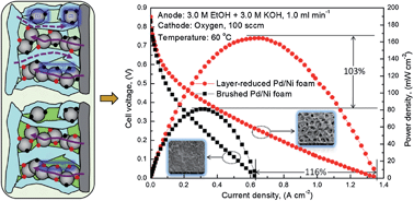
An ideal electrode architecture that boosts the performance of anion-exchange membrane direct liquid fuel cells needs the electrode design to meet all the requirements of electrochemical kinetics and mass and charge transport characteristics. In this regard, here we propose a facile, well-controlled, and binder-free layer reduction method for preparing a three-dimensional foam electrode, which enables the catalytic particles to be directly reduced on the surface of the metal foam. This innovative layer reduction method not only avoids the formation of large catalytic aggregation, but also promises a thin and porous catalyst film that presents a sponge-like morphology uniformly coated onto the skeleton, thus both improving the electrochemical kinetics and enhancing the mass and charge transport of species. The results demonstrate that the application of the layer-reduced Pd/Ni foam electrode in an anion-exchange membrane direct ethanol fuel cell enables a peak power density and the maximum current density as high as 164 mW cm−2 and 1.34 A cm−2 at 60 °C, respectively, which are 1.03 and 1.16 times higher than those of the conventional design.


1 Introduction

Direct liquid fuel cells (DLFCs) that directly convert the chemical energy stored in liquid fuel (e.g., alcohol and acid) into electricity have been considered as one of the most promising power sources for portable and mobile applications, mainly due to their inherent advantages, including high energy density, facile storage and transportation, and fast refueling.1–6 DLFCs can be divided into two types based on the electrolyte membrane used: proton-exchange membrane (PEM) DLFCs and anion-exchange membrane (AEM) DLFCs. Owing to the fact that the electrochemical kinetics of both anode and cathode reactions is faster in alkaline media than in acid media, and thus low-cost Pt-free metals can be employed as the electro-catalyst, AEM DLFCs have recently attracted increasing attention,7–14 especially for the AEM direct ethanol fuel cell (DEFC) as ethanol is non-toxic and can be massively produced from biomass.15–17

Presently, a barrier in developing the AEM DEFCs is that the design of the electrode architecture limits the cell performance, primarily because the electrode design is just directly borrowed from two typical preparing methods for conventional PEM DEFCs: (i) the catalyzed-diffusion media (CDM) method, i.e., the well-dispersed catalyst inks, which consist of catalytic particles and ionomer, are directly brushed onto the surface of the micro-porous layer that is interfaced with a backing layer; and (ii) the catalyst-coated membrane (CCM) method, i.e., the well-dispersed catalyst inks are directly sprayed onto one side of the proton-exchange membrane, and then placed on the diffusion layer that is composed of a micro-porous layer-covered backing layer. These two methods for preparing electrode structure have been proved to enable the PEM DEFCs to have a high cell performance, however, they are not well suitable for AEM DEFCs:18−20 Fig. 1a illustrates the electrochemical reaction regions in PEM DEFCs, and it is seen that triple-phase boundary is comprised of ion-conducting phase, electron-conducting phase and liquid phase. Clearly, to enlarge the triple-phase boundary of PEM DEFCs, it is critical to maximize the ionomer/catalyst/reactant interface regions (represented by the red sphere symbols). Therefore, the presence of high-conductivity cation ionomer in catalyst layer of PEM DEFCs markedly improves the cell performance. Although appealing, it should be noted that some potential triple-phase boundary regions are deactivated due to lacking the electron-conducting pathway (see the marked zone 1 in Fig. 1a), reactant-delivering pathway (see the marked zone 2 in Fig. 1a), or proton-conducting pathway (see the marked zone 3 in Fig. 1a). It is attractive that this problem can be to a great extent solved in AEM DEFCs, since the presence of the alkali in fuel solution allows the reactant-delivering pathway also to be severed as an ion-conducting pathway, namely, conventional triple-phase boundary becomes two-phase boundary as shown in Fig. 1b. It is believed that when feeding liquid electrolyte to fuel, the deactivated zone that is lack of ion-conducting pathway can be activated. Thereby, unlike in PEM DEFCs, maximizing the catalyst/reactant interface regions is regarded as to be essential to AEM DEFCs. Accordingly, the conventionally conceptual electrode design of PEM DEFCs needs to be modified to satisfy the need of the AEM DEFCs.


image file: c4ra01399a-f1.tif
Fig. 1 Schematic illustration of the catalyst layer and the regions (in red color) of (a) triple-phase boundary, and (b) two-phase boundary.

In developing electrodes of the DLFCs, rather than focusing on the conventional design, special attention has been concentrating on the metal foam-based electrodes.21–25 Xu et al.21 prepared a 3D hierarchically structured Pd electrode by directly electrodepositing Pd nanoparticles on the nickel foam, which displayed the improved electrocatalytic activity and stability for ethanol oxidation. Sun et al.22 reported a novel multiscale Pd–Ag catalyzed porous cathode for the magnesium–hydrogen peroxide fuel cell by electrodeposition of Pd onto Ag coated nickel foam surface, the new cathode presented a maximum power density of 140 mW cm−2. Recently, Wang et al.23 prepared a novel three-dimensional electrode consisting of Pd doped porous Ni film supported on Ni foam by electrodeposition using hydrogen bubbles as a dynamic template, and showed the high performance toward NaBH4 electrooxidation. Verlato et al.24 fabricated the Pd-modified Ni foam electrodes by a spontaneous deposition method, the oxidation of alcohols showed that the peak current increased with increasing Pd loading in a sub-linear way. More recently, Cao et al.25 developed a simple and green hard template approach for fabricating noble metals surface-modification of non-noble metal, and the catalytic performance and stability of Pd-modified Co/Ni foam electrodes towards H2O2 reduction were examined.

Literature review indicates that an ideal electrode architecture that boosts the performance of anion-exchange membrane direct liquid fuel cells needs the electrode design to meet all the requirements of electrochemical kinetics and mass and charge transport characteristics. Being motivated by this, in this work, we proposed a facile, well-controlled, and binder-free layer reduction method for preparing a three-dimension foam electrode, which enables catalytic particles to be directly reduced onto the surface of the metal foam. This innovative layer reduction method not only avoids the formation of large catalyst aggregation, but also promise thin and porous catalyst film that presents sponge-like morphology uniformly coated onto the skeleton, thus improving the electrochemical kinetics and enhancing the mass and charge transport of species. To characterize the new electrode, an anion-exchange membrane direct ethanol fuel cells with the new anode electrode was designed, fabricated and tested. Experimental results show that the new anode yields a better performance than the conventional design, the maximum current density reaches as high as 1.34 A cm−2, which is comparable to the hydrogen-based proton exchange membrane fuel cell.

2 Experimental

2.1 Electrode preparation

A facile, well-controlled, and binder-free layer reduction method (Fig. S1) is proposed for preparing 3D Pd/Ni electrode, which is referred to as layer-reduced Pd/Ni foam hereafter. It is proved that the method enables the catalytic particles to be directly reduced onto the surface of the metal foam with the aid of the reductant. Before preparing the layer-reduced Pd/Ni foam electrode, the Ni foam (RECEMAT BV, Netherlands) was treated as follows. Ni foam was first degreased in acetone for 1 h, and then immersed in 0.5 M hydrochloric acid solution for 10 min to remove the oxide layer and etch the metal surface, and finally was washed with deionized (DI) water to remove chemicals. The treated Ni foam was stored in DI water prior to use. The layer reduction method (Fig. S1) for preparing Pd/Ni foam electrode was described as follows: (1) the precursor of 15 mM Na2PdCl4 (Sigma-Aldrich) aqueous solution was titrated into the Ni foam; (2) after the precursor uniformly coated onto the surface of the skeleton, the reductant of 5 mM NaBH4 mixed with 2.5 mM NaOH aqueous solution was slowly titrated onto the Ni foam to reduce Pd ions; (3) the as-prepared Pd/Ni foam electrode was rinsed with deionized (DI) water to remove excessive reductant; (4) the cleaned electrode was dried in the air for 1 min by a blower at 60 °C; (5) the electrode was weighed to determine the Pd loading, and repeated the aforementioned procedures until the required Pd loading was achieved; and (6) the prepared Pd/Ni foam electrode was stored in DI water prior to use.

2.2 Structural characterization

The as-prepared layer-reduced Pd/Ni foam electrode was characterized by scanning electron microscope (SEM), X-ray diffraction (XRD) and X-ray photoelectron spectroscopy (XPS) technologies. The SEM image was obtained with a high-resolution Helios NanoLabTM 600i system. The XRD test was carried out using a shimadzu XRD-7000 diffraction system with a Cu Kα source operating at 40 keV and 40 mA. And the XPS characterization was conducted with a AXIS ultra DLD system using Al monochromatic X-rays at a power of 120 W.

2.3 Electrochemical characterization

Cyclic voltammetry (CV) experiments were conducted in a three-electrode electrochemical cell that is assembled with an Hg–HgO (MMO, 1.0 M KOH, 0.098 V vs. SHE) electrode and a Pt foil as the reference and counter electrodes, respectively. The tailored layer-reduced Pd/Ni foam electrode was used as the working electrode. CV tests were then conducted at a scan rate of 50 mV s−1 in 1.0 M KOH solution and 1.0 M ethanol–1.0 M KOH mixed solution, which were saturated by nitrogen gas.18 All the solutions were prepared from analytical grade reagents and DI water.

2.4 Cell performance evaluation

Cell performance was tested in an in-house fabricated membrane electrode assembly (MEA) consisting of a home-made anode, an anion-exchange membrane (A201, Acta S.p.A), and a home-made cathode. To compare the performance of different anodes, both the layer-reduced Pd/Ni foam anode and CDM method-fabricated conventional anode were ensured with the same Pd loading of 3.0 mg cm−2. The conventional MEA was prepared as reported in detail elsewhere.18,19 In brief, carbon supported non-precious metal catalyst, commercial Fe–Cu–N4/C (Acta 4020),5,26 was employed as the cathode catalyst, and commercial 30 wt% Pd/C (Sigma-Aldrich) was used as the anode catalyst. The catalyst inks were prepared by mixing the catalysts and I2 anion-exchange ionomer (Acta S.p.A, Italy) with 1-propanol as the solvent. The content of the I2 was about 5 wt%. The catalyst inks were stirred continuously in an ultrasonic bath for 10 min to ensure that they were well dispersed. On the anode, the prepared anode catalyst inks were directly brushed onto the surface of the Ni foam that served as the backing layer to form an anode electrode (hereafter referred to as brushed Pd/Ni foam). It should be noted that this type of anode electrode structure has distinct catalyst and diffusion layers. On the cathode, the micro-porous layer consisting of 40 wt% of PTFE and 4.0 mg cm−2 carbon black (Vulcan XC-72), was prepared and applied to the carbon cloth (ETEK, Type A) with 20 wt% PTFE wet-proofing treatment. Subsequently, the as-prepared cathode catalyst inks were directly brushed onto the surface of the micro-porous layer with the catalyst loading of 2.0 mg cm−2. An electrochemical workstation (AUTOLAB PGSTAT302N, Eco Chemie B.V.) linked to a computer interface was employed to adjust the discharge condition and recorded the voltage–current curves. The aqueous solution was supplied to anode by a peristaltic pump at a flow rate of 1.0 ml min−1, and 95% oxygen without humidification at ambient pressure with a flow rate of 100 standard cubic centimeters per minute (sccm) was fed to cathode by a mass flow controller (Omega FMA series, USA).

3 Results and discussion

Fig. 2a and b show the SEM images of the as-treated Ni foam. It can be seen that the Ni foam that contains a gas pore-interconnected network has a three-dimensional cellular structure, thus facilitating the species transport and electronic conduction. The surface morphologies of the as-prepared electrode at different magnifications are shown in Fig. 2c and d. It is observed that after depositing catalytic particles onto the surface of the Ni foam, the smooth surface (Fig. 2b) becomes rough (Fig. 2d), and a thin film is clearly coated onto the skeleton of the Ni foam, indicating the successful deposition of Pd nano-particles on the Ni foam, as is further evidenced by the EDS (see the lower-right inset in Fig. 2d). More interestingly, unlike the electrodeposited Pd/Ni foam that has a hierarchical structure and contains many island-like Pd grains,21 the as-prepared layer-reduced Pd/Ni electrode presents a sponge-like loose structure as shown in the upper-right inset in Fig. 2d, promising thin and porous catalyst film uniformly coated onto the skeleton. Additionally, compared with the electrodes resulted from conventional impregnation-reduction methods,27 it is believed that the layer-reduced Pd/Ni foam electrode has three advantages including (i) increased electrochemical surface area (ECSA): the as-proposed layer reduction method allows the deposition of Pd particles on the Ni foam layer by layer, thus avoiding the formation of large Pd aggregations, and extending the ECSA; (ii) reduced loss of precursor chemical: followed by the quantitative titration step-by-step, the precursor chemical is directly in situ reduced on the Ni foam, thereby avoiding the unwanted reactions in the bulk solution; and (iii) more uniform catalyzed-foam electrode: before reacting to the reductant, the titrated precursor has enough time to penetrate through the Ni foam from one side to another, and leads to well-dispersed precursor that covers the inner surface of Ni foam and enables the uniformity of the catalyzed-foam electrode.
image file: c4ra01399a-f2.tif
Fig. 2 Surface morphologies: (a) and (b) the Ni foam; (c) and (d) the layer-reduced Pd/Ni foam electrode.

The bulk structural information of the layer-reduced Pd/Ni foam electrode was achieved by XRD pattern as shown in Fig. 3. It is seen that there exist seven peaks in the 2θ range from 20 to 90°. The diffraction peaks located at the 2θ values of 44.54°, 51.94°, and 76.43° are assigned to the (1 1 1), (2 0 0), and (2 2 0) peaks of face-centered cubic crystalline Ni (JCPDS 04-0850), respectively,21 and the other four peaks at the 2θ of 40.06°, 46.41°, 68.01°, and 82.06° corresponds, respectively, to (1 1 1), (2 0 0), (2 2 0), and (3 1 1) diffraction peaks of face-centered cubic crystalline Pd (JCPDS 46-1043).21,28 The XRD result further confirms that the Pd catalyst has successfully been coated onto the skeleton of the Ni foam. It can also be observed from Fig. 3 that no significant peak shift for both Pd and Ni exists, indicating that almost no alloy occurs between Ni and Pd for the 3D Pd/Ni electrode prepared by the layer reduction method. This experimental result is in agreement with that reported previously.28


image file: c4ra01399a-f3.tif
Fig. 3 XRD pattern of the layer-reduced Pd/Ni foam electrode.

The surface composition and oxidation state of the metals in the layer-reduced Pd/Ni foam electrode were analyzed by XPS spectra and compared with that of the treated Ni foam. The Pd 3d spectra (Fig. S2) indicate that the Pd coated on the surface of layer-reduced Pd/Ni foam exists mainly in its metallic state (Table S1). The Ni 2p XPS spectra (Fig. S3) reveal the contents of metallic Ni and NiO on the surface of layer-reduced Pd/Ni foam electrode decrease as compared with that in the pristine Ni foam. Conversely, the contents of nickel hydroxides, Ni(OH)2 and NiOOH increase (Table S2). It is expected that the nickel hydroxides that become the predominant component on the top skeleton of the layer-reduced Pd/Ni foam will facilitate the ethanol oxidation reaction (EOR) in alkaline media.

Cyclic voltammetry measurements were employed to investigate the catalytic activity of both the layer-reduced Pd/Ni foam electrode and the conventional brushed Pd/Ni foam electrode toward the EOR in alkaline media. Fig. 4 shows the CV curves of the layer-reduced Pd/Ni foam electrode, brushed Pd/Ni foam electrode and the pristine Ni foam in 1.0 M KOH at a scan rate of 50 mV s−1. The electrochemically surface area (ECSA) of the two electrodes can be obtained by calculating the PdO reduction charge in the CV curves according to the following equation:29

 
ECSA = Q/qm (1)
where Q is the coulombic charge by integrating peak area of the reduction of PdO (μC), q the charge value of 405 μC cm−2 for the reduction of PdO monolayer,30 and m the Pd loading on the working electrode (mg). The ECSA values of layer-reduced Pd/Ni foam and brushed Pd/Ni foam electrodes are, respectively, 63 and 40 m2 g−1, demonstrating that the layer-reduced Pd/Ni foam electrode yields a much larger ECSA. The possible reasons for the difference can be explained by two aspects. On one hand, the absence of the binder in catalyst film of layer-reduced Pd/Ni foam electrode will expose more active sites to the fuel. On the other hand, the thin catalyst film growing in layer-reduced Pd/Ni foam electrode presents a sponge-like loose structure resulting in increased catalytic active sites. Fig. 5 compares positive direction scans of the EOR on the layer-reduced Pd/Ni foam electrode, brushed Pd/Ni foam electrode and the pristine Ni foam electrode in 1.0 M ethanol and 1.0 M KOH aqueous solution at a scan rate of 50 mV s−1. As is seen from the figure, the layer-reduced Pd/Ni foam electrode shows the highest catalytic activity toward the EOR in alkaline media among the three samples, in terms of both the onset potential and the maximum current. The onset potential of the EOR on the layer-reduced Pd/Ni foam electrode is 0.27 V, 0.46 V on brushed Pd/Ni foam electrode, and 0 V on pristine Ni foam electrode. The maximum current of the EOR on the layer-reduced Pd/Ni foam electrode is 0.2 A, 0.12 A on brushed Pd/Ni foam electrode, and 0.001 A on pristine Ni foam electrode. In addition to the preceding greatly increased ECSA, through comparing the specific activity (i.e., the current density normalized by ECSA) of the EOR on the layer-reduced Pd/Ni foam electrode and brushed Pd/Ni foam electrode (Fig. S4), it is proved that the high electrochemical kinetics of the EOR on the layer-reduced Pd/Ni foam electrode in alkaline media also benefits from an improved concurrent promotion effect from nickel hydroxides on the surface of the layer-reduced Pd/Ni foam according to the following reversible redox:31
 
Ni(OH)2 + OH ↔ NiOOH + H2O + e (2)


image file: c4ra01399a-f4.tif
Fig. 4 CV curves of the different electrodes in 1.0 M KOH at a scan rate of 50 mV s−1.

image file: c4ra01399a-f5.tif
Fig. 5 Positive direction scans of EOR on different electrodes in 1.0 M ethanol and 1.0 M KOH aqueous solution at a scan rate of 50 mV s−1.

It should be noted that when fabricating the conventional brushed Pd/Ni foam electrode, the catalyst layer is usually formed by brushing the catalyst ink onto the surface of the Ni foam. This as-obtained thick and dense catalyst layer makes little Pd particles contact with the surface of Ni foam, thereby leading to the negligible concurrent promoting effect. In contrast, for the layer-reduced Pd/Ni foam electrode, Pd particles are directly deposited onto the surface of the Ni foam, and the catalyst film of the layer-reduced Pd/Ni foam electrode is much thinner and looser, thus resulting in a relatively higher concurrent promotion effect. As a result, the layer-reduced Pd/Ni foam electrode yields a great higher catalytic activity than the brushed Pd/Ni foam electrode.

Fig. 6 and 7 compare the polarization and power density curves of AEM DEFCs with two different MEAs, both of which consisted of the same cathode, the same AEM while different anodes. One is the conventional brushed Pd/Ni foam electrode (represented by the square symbols) and the other is the new layer-reduced Pd/Ni foam electrode (represented by the circle symbols). As shown in Fig. 6, when feeding 1.0 M ethanol solution mixed with 1.0 M KOH to the anode at 60 °C, the AEM DEFC with the layer-reduced Pd/Ni foam anode shows a higher performance, the open-circuit voltage (OCV) and the peak power density for layer-reduced Pd/Ni foam anode are, respectively, 0.76 V and 54.62 mW cm−2, and that for the AEM DEFC with the brushed Pd/Ni foam anode are 0.62 V and 37.51 mW cm−2, respectively. The increase of 0.14 V in the OCV indicates that the improved cell performance of the AEM DEFC with the layer-reduced Pd/Ni foam anode is mainly attributed to the enhanced electrochemical kinetics of the EOR on Pd. When increasing the concentration of both the ethanol and KOH to 3.0 M, it can be seen from Fig. 7 that the AEM DEFC with the layer-reduced Pd/Ni foam anode yields a much higher performance than that with the conventional design does, in terms of both the peak power density and the maximum current density. The peak power density for the AEM DEFC with the new anode is 164 mW cm−2, which is 1.03 times higher than that of the conventional anode. It is also seen that the use of the layer-reduced Pd/Ni foam anode yields a maximum current density of 1.34 A cm−2, which is 1.16 times higher than the conventional design, and also is comparable to the hydrogen-based proton exchange membrane fuel cell (PEMFC).32,33 The improved performance with the layer-reduced Pd/Ni foam anode are mainly due to (i) the increased ECSA as confirmed from the Fig. 4, and (ii) the enhanced mass transport, which can be attested from the surface morphology of the anode electrode as shown in the inset of Fig. 7. It can be observed that the conventional electrode has a separated, thick and dense catalyst layer, while the new electrode illustrates a three-dimensional pore-opened integrated structure. Those reveal that the layer-reduced Pd/Ni foam electrode has a higher permeability that facilitates the species transport, lowering transport resistance, resulting in the enhanced mass transport.18


image file: c4ra01399a-f6.tif
Fig. 6 Polarization and power density curves of AEM DEFCs with different anode electrodes (anode: 1.0 M ethanol and 1.0 M KOH aqueous solution).

image file: c4ra01399a-f7.tif
Fig. 7 Polarization and power density curves of AEM DEFCs with different anode electrodes (anode: 3.0 M ethanol and 3.0 M KOH aqueous solution).

4 Conclusions

A current barrier in developing the AEM DEFCs is that the design of the electrode architecture greatly limits the cell performance. To address this issue, we proposed a facile, well-controlled, and binder-free layer reduction method for the preparation of a 3D Pd/Ni foam electrode, which enables the catalytic particles to be directly in situ reduced onto the surface of the metal foam. This innovative layer-reduced Pd/Ni foam electrode mainly showed three advantages: (i) increased electrochemical surface area; (ii) reduced loss of precursor chemical; and (iii) formation of more uniform catalyzed-foam electrode. SEM images demonstrated the new layer-reduced Pd/Ni foam electrode presented a sponge-like loose structure, making the thin catalyst film coated onto the skeleton more porous. XPS analyses revealed that the nickel hydroxides became the predominant component on the top skeleton of the layer-reduced Pd/Ni foam, facilitating the EOR in alkaline media. CV results proved the layer-reduced Pd/Ni foam electrode had higher catalytic activity toward the EOR in alkaline media, compared with both the brushed Pd/Ni foam electrode and pristine Ni foam electrode. Fuel cell performance tests indicated that the AEM DEFC with the layer-reduced Pd/Ni foam anode could yield a peak power density as high as 164 mW cm−2, which was 1.03 times higher than that with the conventional anode, and a maximum current density of 1.34 A cm−2, 1.16 times higher than the conventional design, and also was comparable to the hydrogen-based proton exchange membrane fuel cell.

Acknowledgements

This work was supported by the National Natural Science Foundation of China (no. U1261112), and the Research Project of Chinese Ministry of Education (no. 113055A).

Notes and references

  1. U. B. Demirci and P. Miele, Energy Environ. Sci., 2009, 2, 627 CAS.
  2. F. Lufrano, V. Baglio, O. Di Blasi, P. Staiti, V. Antonucci and A. S. Aricò, Phys. Chem. Chem. Phys., 2012, 14, 2718 RSC.
  3. A. Serov, A. Aziznia, P. H. Benhangi, K. Artyushkova, P. Atanassov and E. Gyenge, J. Mater. Chem. A, 2013, 1, 14384 CAS.
  4. Z. Guo and A. Faghri, J. Power Sources, 2006, 160, 1183 CrossRef CAS PubMed.
  5. Y. S. Li, Y. L. He and W. W. Yang, Int. J. Hydrogen Energy, 2013, 38, 13427 CrossRef CAS PubMed.
  6. H. Huang and X. Wang, J. Mater. Chem., 2012, 22, 22533 RSC.
  7. Y. S. Li, T. S. Zhao and R. Chen, J. Power Sources, 2011, 196, 133 CrossRef CAS PubMed.
  8. Z. Ogumi, K. Matsuoka, S. Chiba, M. Matsuoka, Y. Iriyama, T. Abe and M. Inaba, Electrochemistry, 2002, 70, 980 CAS.
  9. E. Antolini, Energy Environ. Sci., 2009, 2, 915 CAS.
  10. Y. S. Li and T. S. Zhao, Int. J. Hydrogen Energy, 2012, 37, 15334 CrossRef CAS PubMed.
  11. J. R. Varcoe and R. C. T. Slade, Fuel Cells, 2005, 5, 187 CrossRef CAS PubMed.
  12. N. Fujiwara, Z. Siroma, S. Yamazaki, T. Ioroi, H. Senoh and K. Yasuda, J. Power Sources, 2008, 185, 621 CrossRef CAS PubMed.
  13. I. Roche, E. Chainet, M. Chatenet and J. Vondrak, J. Phys. Chem. C, 2007, 111, 1434 CAS.
  14. H. Lee, K. Liu, L. Tsai, J. Lai and C. Chao, RSC Adv., 2014, 4, 10944 RSC.
  15. G. Z. Hu, F. Nitze, X. Jia, T. Sharifi, H. R. Barzegar, E. Gracia-Espino and T. Wågberg, RSC Adv., 2014, 4, 676 RSC.
  16. Z. Zhang, C. Zhang, J. Sun, T. Kou and C. Zhao, RSC Adv., 2012, 2, 11820 RSC.
  17. H. Yan, Z. Bai, S. Chao, L. Yang, Q. Cui, K. Wang and L. Niu, RSC Adv., 2013, 3, 20332 RSC.
  18. Y. S. Li and T. S. Zhao, Int. J. Hydrogen Energy, 2011, 36, 7707 CrossRef CAS PubMed.
  19. Y. S. Li and T. S. Zhao, Int. J. Hydrogen Energy, 2012, 37, 4413 CrossRef CAS PubMed.
  20. Y. S. Li, T. S. Zhao and Z. X. Liang, J. Power Sources, 2009, 187, 387 CrossRef CAS PubMed.
  21. Y. L. Wang, Y. Q. Zhao, C. L. Xu, D. D. Zhao, M. W. Xu, Z. X. Su and H. L. Li, J. Power Sources, 2010, 195, 6496 CrossRef CAS PubMed.
  22. W. Yang, S. Yang, W. Sun, G. Sun and Q. Xin, Electrochim. Acta, 2006, 52, 9 CrossRef CAS PubMed.
  23. K. Cheng, D. Cao, F. Yang, D. Zhang, P. Yan, J. Yin and G. Wang, J. Power Sources, 2013, 242, 141 CrossRef CAS PubMed.
  24. E. Verlato, S. Cattarin, N. Comisso, A. Gambirasi, M. Musiani and L. Vázquez-Gómez, Electrocatalysis, 2012, 3, 48 CrossRef CAS PubMed.
  25. F. Yang, K. Cheng, K. Ye, X. Xiao, F. Guo, G. Wang and D. Cao, J. Power Sources, 2014, 257, 156 CrossRef CAS PubMed.
  26. J. Qi, L. Xin, Z. Zhang, K. Sun, H. He, F. Wang, D. Chadderdon, Y. Qiu, C. Liang and W. Li, Green Chem., 2013, 15, 1133 RSC.
  27. L. An, T. S. Zhao and J. B. Xu, Int. J. Hydrogen Energy, 2011, 36, 13089 CrossRef CAS PubMed.
  28. S. Y. Shen, T. S. Zhao, J. B. Xu and Y. S. Li, J. Power Sources, 2010, 195, 1001 CrossRef CAS PubMed.
  29. R. N. Singh, A. Singh and Anindita, Int. J. Hydrogen Energy, 2009, 34, 2052 CrossRef CAS PubMed.
  30. R. Pattabiraman, Appl. Catal., A, 1997, 153, 9 CrossRef CAS.
  31. S. Y. Shen, T. S. Zhao, J. B. Xu and Y. S. Li, Energy Environ. Sci., 2011, 4, 1428 CAS.
  32. J. Peron, Z. Shia and S. Holdcroft, Energy Environ. Sci., 2011, 4, 1575 CAS.
  33. E. Quartarone and P. Mustarelli, Energy Environ. Sci., 2012, 5, 6436 CAS.

Footnote

Electronic supplementary information (ESI) available: Supplementary figures and tables. See DOI: 10.1039/c4ra01399a

This journal is © The Royal Society of Chemistry 2014