Analysis of slumping on nanoimprint patterning with pseudoplastic metal nanoparticle fluid
Li Dongxuea,
Su Yufengb,
Xia Weiweia,
Liu Chaorana,
Wang Wena,
Wang Pana and
Duan Zhiyong*a
aPhysical Engineering College, Zhengzhou University, Zhengzhou, 450001, China. E-mail: duanzhiyong@zzu.edu.cn
bMechanical Engineering College, Zhengzhou University, Zhengzhou, 450001, China
First published on 19th June 2014
Abstract
Slumping of patterning in the demolding process is a significant problem when pseudoplastic metal nanoparticle fluid is used as the resist material in nanoimprinting, which adversely affects the fidelity of imprint patterning. A theoretical slumping model is proposed to study the influence of the shear-thinning of pseudoplastic fluid on the patterning. The model revealed, on the basis of the microstructure force analysis at the end of demolding, that the critical viscosity increased with the increase of consistency coefficient or rheological index, decreased with the increase of surface tension coefficient, and was independent of density. It was also confirmed that a larger demolding velocity led to a greater degree of viscosity decrease. These results provide a theoretical reference for higher fidelity patterning in nanoimprint lithography with pseudoplastic metal nanoparticle fluid.
1 Introduction
Chou et al. proposed nanoimprint lithography (NIL) in 1995,1 and it has been considered to be one of the supporting technologies for patterning by the International Technology Roadmap for Semiconductors (ITRS) since 2003. NIL has been extensively researched and quickly developed due to its many advantages, such as low cost, high yield, simple process, and high fidelity. In recent years, the minimum feature size achieved with NIL is 2.4 nm,2 while the resolution ratio with a flexible template, which overcomes substrate surface irregularities, reaches 12.5 nm.3 At present, many technologies, such as thermoplastic,4 ultrasonic,5 ultraviolet,6 electrostatic,7 gasbag press,8 direct metallic patterning,9 flexible template,3 micro-contact,10 and reversal,11 are utilized during NIL. Originally, the patterning resist was composed of polymethylmethacrylate (PMMA), but additional materials that are now utilized as resists include ultraviolet resists, polydimethylsiloxane (PDMS), metal thin film, Si, and metal nanoparticles encapsulated with a hexanethiol self-assembled monolayer.While the fidelity of imprint patterning is very important in NIL, the template and resist directly affect imprint patterning. Newtonian fluid is mainly used as the resist; however, Newtonian fluid has the drawbacks of low filling degree of the template and long filling time. For this reason, pseudoplastic metal nanoparticle fluid (PMNF) has been proposed as a resist. PMNF exhibits shear-thinning under shear stress, which effectively enhances the filling degree of the template and shortens the filling time.12 The metal nanoparticles are easily transferred to bulk metallic patterning at low temperatures, which realizes the direct imprint of metal micropatterning. In addition, the gas pressing method, which eliminates vibration,13 can effectively improve the uniformity of the pressing force, which also benefits the fidelity of patterning and prolongs the service life of the template.14,15
When PMNF is used as the resist in NIL, three significant problems arise concerning the preservation of the transfer patterning morphology. The first is the fracture on the neck of the transfer patterning at the beginning of demolding; the second is the slump on the top of the transfer patterning because of the shear-thinning property when the demolding is finished; and the last is the morphology of bulk metal patterning, when the solvent is evaporated and metal nanoparticles are melted. At the beginning of demolding, the bottom of the imprint pattern, which connects the resist in the template and the resist on the substrate, is subject to excessive stress. Therefore, necking or even fracture is likely to happen, leading to damaged imprint patterning. A previous study has solved the problem by obtaining the effects of the friction coefficient, the Hamaker constant, the aspect ratios of the patterning, and the size of the metal nanoparticles on the bottom fracture.16 The current study mainly analyzes the second problem, and analysis of the third problem is underway.
During demolding, the friction between the template and the boundary fluid of patterning results in the shear-thinning of PMNF. When the viscosity of the PMNF boundary fluid decreases, parts of the patterning structure may slump, which decreases the fidelity of the patterning. The patterning microstructure is assumed to be a cube, the length W, the width R and the height H, respectively, where W is decided by the actual patterning that is needed, R ranges from dozens to one hundred nanometers, and H is approximately several hundred nanometers. Because the four uppermost corners of the microstructure suffer from edge effects and the longest friction time during the demolding, their shear-thinning extent is the most obvious. When their viscosity is small enough, the fluid starts to flow and the microstructure slumps, which would directly decrease the fidelity and resolution ratio of the patterning.
After demolding, the shear-thinning of fluid does not exist anymore due to the disappearance of the friction force. The viscosity of the microstructure returns to its initial value gradually over time. Thus, the moment when the template completely separates from the microstructure is critical.
2 Slumping model
In order to confirm the shape and size of the slumping structure, a slumping model is proposed based on a theoretical fidelity height (TFH). As shown in Fig. 1(a), the TFH H′ starts from the central point of the bottom surface and goes through the central point of the top surface. The lines, which are helpful to denote the slumping interface, are marked by four dotted red lines. They go through the highest point of H′ and the lower endpoint of each b. In addition, b is a part of H and begins from the top of H. Taking the front left structure as an example, the dotted red line intersects the top surface of the microstructure at point E. The section through point E is the interface between the front-left slumping structure and the master microstructure, which is marked by the blue area S. | ||
| Fig. 1 (a) Three-dimensional slumping model based on TFH. (b) Four slumping-bodies of the microstructure. | ||
The shape and size of the slumping structure is determined by pseudoplastic fluid thixotropism and the thinning extent of the microstructure edges. At the end of demolding, the viscosity reduction of fluid on the top of the microstructure corners is the largest. Simultaneously, the fluid viscosity at the bottom of the microstructure decreases, but the reduction is not as great as that at the top. The cross-sectional horizontal length of the slumping structure increases from the bottom to the top of the microstructure. Therefore, the shape of the slumping structure is a tetrahedron; however, the size cannot be ensured because of many uncertain factors.
The volume of the slumping structure increases with the decrease of H′, and the shape of the four slumping-bodies will become a whole compatible slumping-body when H′ is short enough. Under the critical condition where the four slumping-bodies precisely begin to roll into one, the right side a of the whole slumping-body becomes equal to half of the width R of the microstructure, namely R/2. When the value of H′ is confirmed, the other right side b of the whole slumping-body is solely determined accordingly. Here, the critical geometric shape of the slumping-body under the value of H′ is determined. Therefore, when b is determined, H′ is greater than the critical value, a is smaller than R/2, the slumping structures are composed of four slumping-bodies, and the higher H′ is, the smaller a is, namely, the smaller the volume of the slumping structures. When H′ is smaller than the critical value, all four slumping structures will be an entity, whose upper side is R. This represents the most significant slumping state, which brings about the worst patterning fidelity. Among all the cases, when a is smaller than R/2, the slumping is the slightest. In this case, when H′ is greater, the demolding process is better in NIL. In theory, H′ can be an arbitrary value from (H − b) (as b equals to H, (H − b) equals to zero) to infinity. When H′ is close to infinity, the slumping interfaces will overlap with the lateral surfaces of the microstructure, no slumping appears during demolding, and now the fidelity of patterning is the most optimal.
In NIL, the slumping cannot be permitted even in the most likely possible slumping case where a is lower than R/2. Under those conditions, no slumping of microstructure has been analyzed in the literature. The integral slumping structures are shown in Fig. 1(b), and they are called a slumping-body with four tetrahedrons. The tetrahedron is composed of three right triangle faces and an isosceles triangle face. Furthermore, the lengths of the two top right sides of the tetrahedron are equal because of the equal shear-thinning effect and are assumed as a, and the third right side is assumed as b, where a ≤ W and a ≤ R, then b ≤ H.
3 Simulation analysis
The process of demolding in NIL is simulated with the COMSOL Multiphysics program. On the edge of the two-dimensional microstructure, five points are selected, as shown in Fig. 2. The initial viscosity of the PMNF is set as 166 Pa s, and the demolding velocity is 100 nm s−1. The fluid viscosity changes of these points during demolding are shown in Fig. 3. | ||
| Fig. 2 The selected points on the edge of the two-dimensional microstructure. | ||
 | ||
| Fig. 3 The fluid viscosity of the five edge points. | ||
It can be seen that in Fig. 3, the fluid viscosity at each point firstly decreases and then increases with time during demolding. The decrease in fluid viscosity is caused by the friction between the template and the pseudoplastic fluid. Nevertheless, the viscosity gradually recovers after the template moves away from the fluid. The simulation results under ideal conditions show that the fluid viscosity nearly recovers to its initial value. However, due to its thixotropy, the viscosity of pseudoplastic fluid is hard to recover up to the initial value during such a short demolding time.
Fig. 3 also shows that the reduction of the viscosities from point 1 to point 5 continuously increases during the demolding. Namely, there is a shear-thinning strengthening tendency from the bottom to the top along the microstructure edges, which is caused by the addition of friction time. The viscosity of the four top corners of the microstructure is the smallest, and the fluid in these areas is likely to flow after demolding, which will lead to patterning slumping. The simulation results are consistent with theoretical expectation, and the slumping model proposed is reasonable.
4 The influence of PMNF parameters
When demolding is finished, the fluid in the four vertices of the microstructure has the minimum viscosity and the strongest tendency to flow. When the viscosity of the vertex fluid reaches the threshold value, the fluid begins to flow. The fluid containing the vertex fluid with a tendency to flow is called the slumping-body, and the remaining fluid of the microstructure is called the master-microstructure. The separatrix surface between the slumping-body and the master-microstructure is called the slumping interface, which is shown by the red lines in Fig. 1(b). A viscosity gradient forms in the fluid on the horizontal section of the microstructure and gradually become larger as the depth grows from the boundary to the center of the microstructure. The slumping interface must lie in the gradient fluid, and the slumping-interface may not be planar because of the character of the PMNF.4.1 Slumping interface
PMNF was prepared by uniformly mixing metal nanoparticles of different sizes that range from 1 to 5 nm in precursor solution. When the slumping-body slides relative to the master-microstructure, there are three situations of metal nanoparticle distribution on the interface: (I) there are no metal nanoparticles on the slumping-interface; (II) there are metal nanoparticles on the slumping-interface, and most of the volume of a metal nanoparticle is in the slumping-body; (III) there are metal nanoparticles on the slumping-interface, but most of the volume of a metal nanoparticle is in the master-microstructure. A cross-sectional view of the microstructure about the metal nanoparticle distribution is shown in Fig. 4(a). When the slumping-body slides, metal-nanoparticle c and d will move with it, but metal-nanoparticle e is stationary, staying in the master-microstructure. The height of a metal nanoparticle inlaid in the relative moving fluid is assumed as h. If h is determined, the friction force between the relative moving fluid and metal nanoparticle is certain, which is true not only in situation II but also in situation III. | ||
| Fig. 4 (a) Metal nanoparticle distribution on the slumping-interface. (b) A metal nanoparticle inlaid in precursor solution. | ||
According to Amontons' law, the static friction force on the contact surface between the metal nanoparticle and the fluid is:
| f = μsFN | (1) |
 | (2) |
Therefore, the static friction force is:
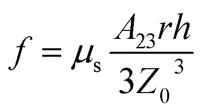
The static friction force f is proportional to h, and when h is close to zero, f should reach its minimum value. Here, it is reasonable to suppose that no metal nanoparticles exist on the slumping-interface, as in situation I.
As the slumping-body is likely to slide when no metal nanoparticles exist in the slumping-interface, the parameters are calculated so that there is no slumping-body sliding. These parameters would be applicable to the other two cases. Then, the following force analysis aims at case I, and the critical relevant parameters of microstructure with no slumping during demolding are obtained.
4.2 Force analysis
Because the microstructure is axisymmetric and the four corners undergo equivalent shear force for the same length of time during demolding, the viscosity changes of the four slumping-bodies are the same. The front-left slumping-body marked as ABCD is chosen as the example for analysis. After demolding, the slumping-body bears the following forces: three atmospheric pressure forces fP1, fP2, fP3, which act on the three right triangle surfaces, surface tension force Fs, intermolecular force Fi between the slumping-body and the master-microstructure, slumping-body gravity G, normal force N on the contact interface, and viscous force Fv. These forces are shown in Fig. 5. Only the forces whose orientations are parallel to cant BCD contribute to the sliding of the slumping-body, and the forces perpendicular to cant BCD are ignored. | ||
| Fig. 5 Force analysis of the slumping-body. | ||

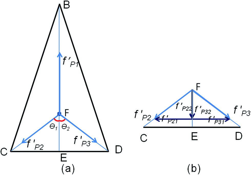 | ||
| Fig. 6 (a) The projections of three atmospheric pressure forces. (b) The components of f′P2 and f′P3. | ||
Therefore, the resultant force parallel to BCD is:
| FP = f′P1 − (f′P22 + f′P32) = 0 | (3) |
That is to say, the atmospheric pressure forces have no contribution to the sliding of the slumping-body.
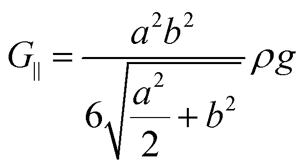 | (4) |
| Fs = σl | (5) |
![[F with combining right harpoon above (vector)]](https://www.rsc.org/images/entities/i_char_0046_20d1.gif) s = 1 + 2 + 3 s = 1 + 2 + 3
| (6) |
| F1 = σlBC, F2 = σlCD, F3 = σlBD |
F1 is perpendicular to line BC on plane ABC, F2 is perpendicular to line CD on plane ACD, and F3 is perpendicular to line BD on plane ABD. The directions of all forces are against the slumping-body. The three forces are resolved and composed in the direction parallel to cant BCD, and the resultant force Fs‖ is
 | (7) |
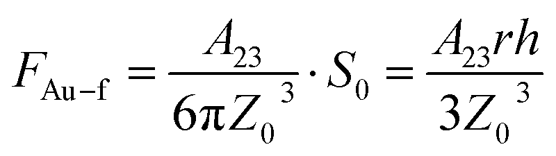
Metal nanoparticles with different sizes are uniformly distributed in precursor solution. Hence, it is hard to calculate the FAu–Au of each metal nanoparticle in the slumping-body, which is provided by all metal nanoparticles in the master-microstructure. All metal nanoparticles in the slumping-body are treated as an entity, and all metal nanoparticles in the master-microstructure are treated as another entity. Their centers of mass are respectively on their own geometric center. FAu–Au between the two entities is on the line through the two centers of mass, as shown in Fig. 7. Au nanoparticles are used in the calculation, the mass of metal nanoparticles in the slumping-body is M1, and the mass of metal nanoparticles in the master-microstructure is M2. Therefore, FAu–Au between the two entities is
 | (8) |

| M2 = RHW × 70% × ρAu × g − 4M1 |
 | ||
| Fig. 7 The intermolecular force between metal nanoparticles. | ||
Based on the calculation, FAu–Au is much less than other forces, so it is negligible to the resultant force.
| Fv = Sτ | (9) |
| τ = ηγ |
Here, τ is shear force per unit area of fluid; S is the area of sliding cant,  ; η is the fluid viscosity on the slumping-interface; γ is called the shear rate and indicates the velocity gradient perpendicular to the flowing direction, γ = dV/dy, dy is the thickness of an infinitely thin fluid layer, while dV is the velocity increment on the distance of dy.
According to the power-law equation of fluid, η = Kγn−1, K represents the consistency coefficient and n denotes the power law index, which can also be called the rheological index. The viscous force is:
 | (10) |
4.3 Critical state analysis
Through the analysis above, only gravity G, surface tension force Fs, and viscous force Fv contribute to the sliding of the slumping-body. In order to prevent the slumping-body from sliding, these forces should meet the relation:| Fs‖ + G‖ ≤ Fv | (11) |
Then, the expressions of all forces are incorporated into eqn (11),

 | (12) |
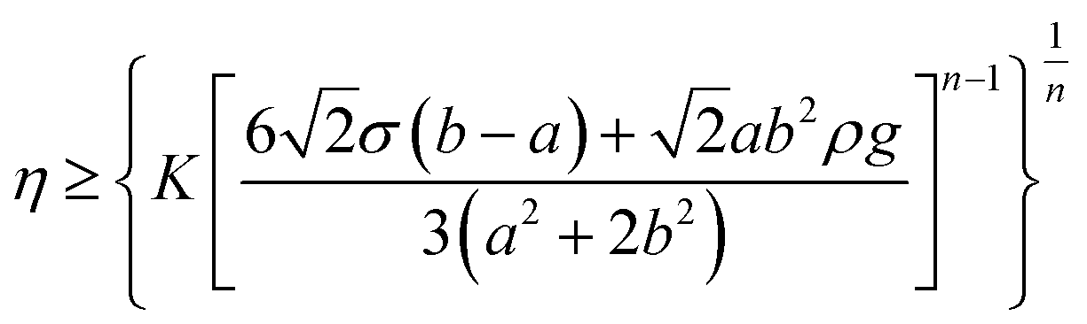
After demolding, if the fluid viscosity on the slumping-interface is satisfied by eqn (12), then there will be no slumping in the microstructure. Here, in order to clarify the description, ηc is used to represent the summation of the complex expression:

The influences of a and b on critical viscosity ηc with other parameters as constants under different initial viscosities of PMNF are discussed, and the curve graphs are shown in Fig. 8.
 | ||
| Fig. 8 The influences of a and b with different initial viscosities. | ||
In Fig. 8, if a is certain, the critical viscosity ηc after demolding is bigger when the initial viscosity η0 is bigger; this phenomenon is also applied to b. When the initial viscosity η0 is fixed, ηc is observed to increase with the increase of a or b. Once again, it is validated that the viscosity changes of the fluid that is closer to the centre of the microstructure are smaller. The increased extent of ηc is more obvious for b; that is to say, the influence of the friction force on the edge is bigger than the accumulated effect in the microstructure.
When the size of the slumping-body is smaller than one tenth of the feature size of the imprinting microstructure patterning, the influence of slumping on the fidelity of patterning can be negligible. Assuming that a = 6 nm and b = 100 nm, the influences of four attribute parameters of PMNF (consistency coefficient K, rheological index n, density ρ, and surface tension coefficient σ) on the critical viscosity ηc after demolding are examined below.
The effect of rheological index n on critical viscosity ηc is shown in Fig. 9(a). Assume that K = 166 Pa sn, σ = 0.01 N m−1, and ρ = 13.81 × 10³ kg m−3. ηc is observed to increase with the increase of n. When n < 0.6, ηc changes slowly; when n > 0.6, the tendency to increase is obvious. When n approaches 1, ηc is close to the initial viscosity of 166 Pa s. The fluid is not pseudoplastic, as n is 1. Only when n is smaller than 1 is the fluid a pseudoplastic fluid. The smaller n is, the stronger the pseudoplastic properties. In order to enhance the filling degree of the template, fluid with great liquidity with a small n is expected. Simultaneously, when n is small, ηc that is obtained after demolding is small, too. A smaller ηc is easier to satisfy eqn (12) for demolding technology, which can ensure good microstructure fidelity. However, n that is too small will increase the difficulty and cost to fabricate PMNF.
 | ||
| Fig. 9 The critical viscosity ηc with rheological index n, consistency coefficient K, density ρ, and surface tension coefficient σ. | ||
The effect of consistency coefficient K on critical viscosity ηc is depicted in Fig. 9(b). Assume that n = 0.8, σ = 0.01 N m−1, and ρ = 13.81 × 10³ kg m−3. It can be seen that ηc increases with the increase of K, and the curve diagram is similar to that obtained with a linear relationship. Similarly, the theoretical ηc obtained from eqn (12) is expected to be small, which indicates that a smaller K should be taken. However, K is linked with the initial viscosity η0, and a large η0 is helpful to maintain the patterning morphology when it is static. Taking the two factors into account, K can be confirmed.
The curve of critical viscosity ηc versus density ρ is drawn in Fig. 9(c). Assume that n = 0.8, σ = 0.01 N m−1, and K = 166 Pa sn. ηc changes little with the increase of ρ, and thus, it can be considered that ηc is independent from ρ. When pseudoplastic fluid is fabricated, the influence of ρ can be ignored.
The curve of critical viscosity ηc versus surface tension coefficient σ is drawn in Fig. 9(d). Assume that n = 0.8, ρ = 13.81 × 10³ kg m−3, and K = 166 Pa sn. It can be seen that ηc decreases with the increase of σ, and when σ is smaller, ηc obviously changes, but it tends to be a stable value finally when σ is big enough. When a small theoretical ηc is considered, σ will be larger; σ is linked with ρ, and the larger ρ is, the larger σ is. Only when PMNF contains more metal nanoparticles will ρ be large, which will also lead to much more difficulty and cost to fabricate PMNF.
5 The influence of demolding velocity
The parameters of PMNF affecting the slumping-interface viscosity η are determined, and their influences on η are indirect. The friction between the template and edges of the microstructure during demolding leads to marginal PMNF shear-thinning. The thinning extent of PMNF varies with the demolding velocity. The bigger the demolding velocity is, the bigger the shear-thinning extent. Therefore, the demolding velocity directly affects the slumping-interface viscosity η. The demolding velocity must not be bigger than the critical value, whose corresponding viscosity η meets eqn (12).5.1 The velocity of the boundary layer
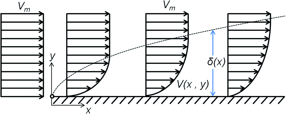
At the beginning of the demolding process, the template is pulled up and instantly has the velocity Vt. During the process, the template is kept moving uniformly with the speed Vt by varying the pull. Because the movement is relative, if we suppose that the value of the template velocity is zero, then the numerical value of microstructure velocity Vm will be equal to Vt, but Vm has the opposite direction with Vt, namely Vm = −Vt.When fluid contacts with a solid wall, it sticks to the solid wall, and the velocity of the adhesive fluid layer is zero. However, the velocity of the fluid near the center of the microstructure is Vm. A separatrix must exist in the microstructure, and the velocity of fluid on the side close to the template of the separatrix is smaller than Vm, while that on the other side of separatrix is equal to Vm. Therefore, the fluid layers, which are located in different positions between the separatrix and template, have different velocities, which results in relative motions. The fluid with relative motions is called the boundary layer of velocity, and its thickness is assumed as δ. The inner frictions in the boundary layer of velocity, which are caused by the relative motions, lead to fluid shear-thinning. Then the fluid viscosity is smaller than η0, and the closer the fluid is to the template, the smaller the viscosity. The fluid in the boundary layer has a viscosity gradient. In fact, it is difficult to identify the separatrix, as δ tends to be infinite when the fluid velocity on the separatrix is entirely equal to Vm. In general, if the fluid velocity on the separatrix reaches 99.5% Vm, the separatrix is accepted, and the thickness of the boundary layer is called δ (995). The boundary layer model of laminar flow can be used to analyze the relative motions between template and microstructure during demolding. The model is shown in Fig. 10.17 The velocity gradient of the fluid layer becomes larger when the fluid is closer to the template. The positive direction of the x-axis indicates the contact surface upward between the template and microstructure, and the positive direction of y-axis denotes the direction vertical to the contact surface with the microstructure inwards. The position of the template is denoted by y = 0.
 | ||
| Fig. 10 The model of velocity of boundary layer. | ||
The shear-thinning effects of fluid are accumulated with the friction time. The thickness of the boundary layer increases because of a sustained separation movement between the template and microstructure; namely, δ increases with the increase of y. The thickness of fluid layers whose viscosities decrease increases with the increase of y. The four possible slumping-bodies on the edge of the microstructure appear to be quadrihedron shaped, just as Fig. 1(b) shows.
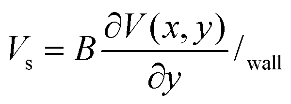
5.2 Slip velocity
The fluid adjacent to the template will intermittently adhere to or separate from the template during demolding. The Knudsen (Kn) of the moving region has the order of 10−2, which indicates that slipping movement is occurring, and relative motion exists on the solid–liquid surface. The velocity of fluid on the template is no longer zero as shown in Fig. 10, but is the slip velocity Vs shown in Fig. 11(a). However, the velocity gradient in the horizontal section of the microstructure still exists. The expression18,19 for the slip velocity is
 | (13) |
 | ||
| Fig. 11 (a) A model of slip velocity; (b) the layers of the viscosity boundary layer. | ||
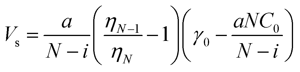
Relative motions between different fluid layers lead to the decrease of fluid viscosity. Therefore, the velocity boundary layer is the viscosity boundary layer at the same time. The viscosity boundary layer is supposed to be uniformly divided into N(1, 2… i…) layers, as shown in Fig. 11(b). The interface between two adjacent fluid layers is considered parallel to the slumping-interface, and the fluid layer adjacent to the template has the minimum viscosity. The initial viscosity of PMNF is η0, and the average viscosity value of each layer is taken. From the internal microstructure, the viscosity of the first layer is η1, the second layer is η2, and so on, and the last layer touching the template is ηN. The fluid-containing layer (i + 1) begins to flow when ηi is small enough. Here, the fluid viscosity on the interface is ηi, and the fluid layer whose viscosity is ηi is in the master-microstructure. The interface between the layer i and the layer (i + 1) is the slumping-interface, so ηi is the slumping-interface viscosity η. Therefore, slip length B19,20 can be expressed as
 | (14) |
5.3 Demolding velocity analysis
A velocity gradient exists in the velocity boundary layer, and the velocity gradient has a gradient itself, which is assumed as C. According to the viscosity feature of the boundary layer, C, which is negative, is related to the fluid character, and x indicates the altitude of the fluid in the microstructure. When PMNF is determined, . The altitude of the fluid is higher, the velocity variation is larger, and the relative motion is fiercer, so the reduction of viscosity is greater. When x = H, fluid has the minimum viscosity. Supposing that C(H) = C0, the velocity variation of the velocity boundary layer of the thin fluid layer containing the upper surface of microstructure is researched. The velocity is assumed as:
| V = αy2 + βy + ε | (15) |
where γ0 is the shear rate matching η0, and then

 ,
,  , ε = Vs.
The fluid velocity is obtained:

 , therefore
Given that  ,
,  ,
,  , η = Kγn−1, the expressions are:
 | (16) |
 | (17) |
 | (18) |
 | (19) |
Then eqn (16) and (17) are incorporated into eqn (15). Therefore, eqn (20) is:
 | (20) |
Expression C0 is replaced,
 | (21) |
 | ||
| Fig. 12 The critical viscosity with demolding velocity. | ||
6 Conclusions
By taking advantage of the shear-thinning of PMNF, the filling degree of the template is improved, and the metal patterning can be directly realized in NIL. However, in order to optimize the service life of the template and the processing time, demolding should be carried out for a short time after imprinting. The shear-thinning of PMNF that is used as the resist during demolding will affect the integrity of patterning. By analyzing the possible slumping-body, these coefficients and physical parameters are obtained under the worst situation where fluid is likely to slide. In order to avoid the appearance of slumping, smaller consistency coefficient, smaller rheological index, and larger surface tension coefficient should be selected, and the demolding velocity should be reduced. These conclusions provide significant theoretical guidance for the fabrication of PMNF and the demolding process in NIL.Acknowledgements
This work is sponsored by the National Natural Science Foundation of China (grant no. 51175479), and the Education Department of Henan Province, China. (grant no. 13A460725, 2013GGJS-001). The authors would like to thank Dr B. Cai for the paper polishing.References
- S. Y. Chou, P. R. Krauss and P. J. Renstrom, Science, 1996, 272(5258), 85–87 CAS.
- F. Hua, Y. Sun, A. Gaur, M. A. Meitl, L. Bilhaut and L. RotKina, et al., Nano Lett., 2004, 4(12), 2467–2471 CrossRef CAS.
- G. Kreindl, M. Kast, D. Treiblmayr and T. Glinsner, et al., Proc. SPIE, 2011, 7970, 79701 CrossRef PubMed.
- H. Yoon, H. S. Cho, K. Y. Suh and K. Char, Nanotechnology, 2010, 21, 105302 CrossRef PubMed.
- H. Mekaru and M. Takahashi, J. Micromech. Microeng., 2009, 19, 125026 CrossRef.
- J. Perumal, T. H. Yoon, H. S. Jang, J. J. Lee and D. P. Kim, Nanotechnology, 2009, 20, 055704 CrossRef PubMed.
- H. Hocheng and T. T. Wen, Microelectron. Eng., 2008, 85, 1652–1657 CrossRef CAS PubMed.
- F. Cheng, S. Y. Yang, S. C. Nian and L. A. Wang, J. Vac. Sci. Technol., B: Microelectron. Nanometer Struct.--Process., Meas., Phenom., 2006, 24, 1724–1727 CrossRef CAS.
- S. H. Ko, I. Park, H. Pan, C. P. Grigoropoulos, A. P. Pisano, C. K. Luscombe and J. M. J. Fréchet, Nano Lett., 2007, 7, 1869 CrossRef CAS PubMed.
- X. M. Zhao, Y. Xia and G. M. Whitesides, J. Mater. Chem., 1997, 7(7), 1069–1074 RSC.
- Y. Tsuji, M. Yanagisawa, H. Yoshinaga and K. Hiratsuka, J. Phys.: Conf. Ser., 2009, 191, 012010 CrossRef.
- W. W. Xia, G. H. Zheng, T. H. Li, C. R. Liu, D. X. Li and Z. Y. Duan, Acta Phys. Sin., 2013, 62(18), 188105 Search PubMed.
- C. R. Liu, J. Z. Yue, T. H. Li, W. W. Xia, D. X. Li and Z. Y. Duan, J. Mech. Eng. Sci., 2014, 228(9), 1634–1642 Search PubMed.
- T. H. Li, G. H. Zheng, C. R. Liu, W. W. Xia, D. X. Li and Z. Y. Duan, IEEE Trans. Nanotechnol., 2013, 12(4), 589–595 CrossRef CAS.
- T. H. Li, G. H. Zheng, C. R. Liu, W. W. Xia, D. X. Li and Z. Y. Duan, Acta Phys. Sin., 2013, 62(6), 068103 Search PubMed.
- W. W. Xia, Y. F. Su, T. H. Li, C. R. Liu, D. X. Li and Z. Y. Duan, RSC Adv., 2013, 3(39), 17851–17859 RSC.
- M. Z. Chen, Fundamentals of viscous Fluid Dynamics, Higher Education Press, Beijing, 2002, pp. 123–130 Search PubMed.
- O. I. Vinogradova, Langmuir, 1995, 11, 2213–2220 CrossRef CAS.
- S. G. Hatzikiriakos, Prog. Polym. Sci., 2012, 37, 624–643 CrossRef CAS PubMed.
- C. W. Wu, G. J. Ma and P. Zhou, Advances in Mechanics, 2008, 38(3), 265–292 Search PubMed.
| This journal is © The Royal Society of Chemistry 2014 |