Preparation and electrochemical performance of a porous polymer-derived silicon carbonitride anode by hydrofluoric acid etching for lithium ion batteries†
Ningning Feng,
Yan Feng*,
Yuzhen Wei and
Xiaopu Zhou
Tianjin Key Laboratory of Structure and Performance for Functional Molecules, Key Laboratory of Inorganic–Organic Hybrid Functional Material Chemistry, Ministry of Education, College of Chemistry, Tianjin Normal University, Tianjin 300387, China. E-mail: hxxyfy@mail.tjnu.edu.cn; Tel: +86-22-2376-1006
First published on 15th April 2014
Abstract
Porous silicon carbonitride (SiCN) ceramics were pyrolyzed from poly(silylcarbondiimide) derivatives, followed by etching with different concentrations of HF aqueous solution (5, 10, 15 and 20 wt%). The morphologies, structures and electrochemical performances of the HF-etched SiCN materials were investigated. The results indicated that the surface of the HF-etched SiCN composites became rough and porous. SiCN-10-HF, one of four HF-etched SiCN samples, showed excellent electrochemical properties as an anode for lithium ion batteries. Charge–discharge measurements indicated that the SiCN-10-HF anode exhibited a high initial specific discharge capacity of 681 mA h g−1 at a current density of 40 mA g−1, which was 2.4 times that of the unetched SiCN anode. After 100 cycles, the discharge capacity of SiCN-10-HF anode delivered 229.3 mA h g−1, which was 5.0 times that of the unetched SiCN anode (45.6 mA h g−1). Additionally, the SiCN-10-HF anode exhibited high rate performance. At a current density of 190 mA g−1, the discharge capacity of the anode was 160 mA h g−1. It was deduced that the formation of nano-sized pores or holes on the surface of the SiCN materials in the HF-etching process not only offered new channels for the intercalation of Li+ but also relieved the volume expansion during the charge and discharge process, resulting in improved capacity, stable cycling and good rate capability.
1. Introduction
Since the first commercial lithium ion battery was produced by the Sony Corporation in 1991, much attention has been paid to the research on rechargeable lithium ion batteries due to their characteristics, such as high energy density, high efficiency and long cycling life.1 Particularly, in the last ten years, the practical applications of lithium ion batteries in portable electronic devices and plug-in hybrid electric vehicles (PHEVs) make them an alternative to replace the conditional use of fossil fuels.2 Currently, the commercial lithium ion battery is based on the migration of lithium ions back and forth between a graphite anode and a layered metal oxide cathode.3 Although the graphite anode has a theoretical capacity of 372 mA h g−1, increasing the number of cycles causes the graphite anode to react with the organic electrolyte to form a passivating solid electrolyte interphase (SEI), resulting in the capacity fading irreversibly.4 Therefore, with respect to the market perspective, new anode materials with high electrochemical performance for more powerful battery systems are urgently needed.Recently, a series of silicon-based materials have been regarded as promising electroactive materials as an alternative to graphite due to their extremely high theoretical specific capacity of 4200 mA h g−1 (even 3500 mA h g−1 under practical conditions).5 Unfortunately, silicon-based anodes suffer from the fact that an extreme volume change of up to 300% occurs during lithiation and delithiation, resulting in mechanical pulverization, capacity degradation and cycling instability.6–9 An effective way to make silicon-based anodes suitable for lithium ion batteries is by either forming an alloy with flexible materials, or by synthesizing porous and mechanically stable Si-based materials.
Polymer-derived ternary silicon carbonitride (SiCN) ceramics satisfy all of the above demands for Si-based anodes in lithium ion batteries. They are controllably synthesized by pyrolysis of polysilazanes or polysilylcarbondiimide precursors at 1000–1700 °C, providing thermal stability, chemical inertness and high charge–discharge capacity.10,11 Based on the above previous study,12–21 our group has investigated these polymer-derived SiCN anodes.22–25 We found that the superior electrochemical performance of SiCN anodes depends on three characteristics of the structure of SiCN ceramics, which is well suited for Li-battery anodes. Firstly, the structure of the SiCN materials is a three-dimensional rigid network consisting of silicon, carbon and nitrogen atoms, which benefits cycle stability for lithium ion batteries; secondly, there are a lot of nano carbon clusters dispersed in the SiCN networks and free dangling bonds of silicon, which work as active sites for the insertion–extraction of Li+, contributing to the high charge–discharge capacity; thirdly, there are many nano-holes or nano-channels in the SiCN network, which provide new smooth Li+ transfer paths to enhance the electrochemical dynamic properties. Despite the high first discharge capacity of SiCN ceramics, their cycle stability is not satisfactory at present. For example, initial specific discharge capacities of SiCN anodes are reported in the range of 700–900 mA h g−1, while the discharge capacity falls to 10–80 mA h g−1 after 30–50 cycles.13,18
In order to improve the electrochemical properties of pure polymer-derived SiCN anodes, we have tried two strategies. The first strategy is carbon content coating or incorporation, using materials such as carbon nanotubes (CNTs),23 graphite24 and graphene.25 With increasing carbon content, the cycle stability and high rate performance of SiCN anodes were improved by 2.0–6.0 times. Meanwhile, the same results have been found by other research groups studying SiCN/carbon composite anodes.16–18,21 The other strategy is to prepare modified SiCN materials with porous surfaces. The merits of the porous anode are the pores or holes on the surface which can offer active sites for the intercalation and immigration of Li+, benefiting the electrochemical performance of the material. Commonly, the porous morphology is obtained using strong corrosive acid, such as hydrofluoric acid (HF). For example, Graczyk-Zajac et al.26 reported that polymer-derived SiOC anodes with a porous surface exhibited high discharge capacity and enhanced cycle stability by etching with HF solution. Accordingly, SiCN and SiOC are both the same kind of polymer-derived ceramic materials, so have features in common in their structures and properties. Therefore, we propose that HF etching may be a good method to prepare our porous SiCN anode material.
Thus, based on our previous work on SiCN anode for Li-ion batteries,22–25 in this work we prepare porous polymer-derived SiCN materials by etching the silica phase of the dense SiCN with 5–20 wt% of HF solution, and investigate their morphology, structure and electrochemical performances. What's more, this is the first time that porous SiCN anodes have been prepared by etching with HF solution. The results indicate that after HF etching, the initial charge–discharge capacity, the reversible discharge capacity and the high-rate performance of the porous SiCN anodes have been prominently improved.
2. Experimental
2.1 Chemicals
Dichlorosilanes were purchased from Alfa-Asear Corp., China and used without purification. 1,2-Ethylenediamine (EDA), triethylamine (TEA), toluene, 2,2-azo-bis-iso-butyronitrile (AIBN) and hydrofluoric acid (HF) were purchased from Tianjin Kewei Corp., China. EDA, TEA and toluene were dried by distillation before used. AIBN and HF were used without purification.2.2 Preparation of the polymer-derived SiCN
The polymer-derived SiCN material was prepared by pyrolyzing a poly(silylcarbondiimide) precursor, which was synthesized by the aminolysis reaction of EDA, TDA and dichlorosilanes. The synthesis details are as follows: a solution of EDA (9.50 g, 0.158 mol) and TEA (30.3 g, 0.30 mol) in 100 mL toluene was placed in a 500 mL three-neck round bottom flask fitted with a reflux condenser, a dropping funnel and an argon inlet. The mixed solution was magnetically stirred. To this solution, dichloromethylsilane (8.2 mL, 0.072 mol) and dichloromethylvinylsilane (10.37 mL, 0.079 mol) in 50 mL toluene was then added slowly from the dropping funnel (about 40 min) to keep the reaction temperature below 40 °C. The reaction mixture was refluxed at 60 °C for 40 min, and then refluxed at 100 °C for 90 min. After that, the reaction mixture was cooled to ambient temperature. The reaction was carried out under an rgon atmosphere. The triethylamine hydrochloride N(C2H5)3·HCl salt was filtered off and the filtrate was rotary evaporated to remove the solvent and other volatile components. The remaining yellow oil was dried at room temperature under argon atmosphere overnight to obtain the poly(silylcarbondiimide) precursor. Then the as-prepared poly(silylcarbondiimide) precursor was cross-linked into a colloidal solid at 80 °C using AIBN as a radical initiator. Then the cross-linked precursor was placed in an Al2O3 crucible and pyrolyzed in an alumina tube furnace under argon flow at 1000 °C for 1 h at a heating rate of 5 °C min−1. Then the as-prepared SiCN samples were powdered and sieved with a 200 meshed standard sieve.2.3 Preparation of porous SiCN materials by HF etching
Etching of the SiCN powders was performed using 5, 10, 15 and 20 wt% of HF aqueous solution. The preparation details are as follows: 1.0 g of the as-prepared SiCN powders were placed in Teflon containers with 20 mL hydrofluoric acid aqueous solution. The solutions were gently stirred at room temperature for 6 h, then filtered and rinsed off with distilled water to remove any residual HF. Finally, the samples were dried in an oven at 100 °C for 24 h. For convenience, the samples formed by etching using 5, 10, 15 and 20 wt% HF solution were denoted as SiCN-5-HF, SiCN-10-HF, SiCN-15-HF and SiCN-20-HF respectively. The chemical synthesis route is shown in Fig. 1.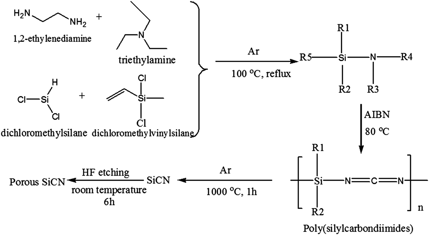 | ||
| Fig. 1 Schematic procedure for the synthesis of porous SiCN material. | ||
2.4 Material characterization
The morphologies of the HF-etching porous SiCN materials were characterized with a scanning electron microscopy system (SEM, FEI Nova Nano 2300) with an accelerating voltage of 15 kV, and a transmission electron microscopy system (TEM, FEI Tecnai G2 F20) operating at 200 kV. The X-ray powder diffraction (XRD) patterns were recorded on a Rigaku D8A X-ray diffractometer (Bruker, Germany) and Cu Kα radiation (λ = 0.154 nm) in the 2θ range of 10–80°. Fourier transform infrared (FTIR) spectra were collected using a Nicolet IR200 automatic infrared spectrometer (Thermo, US) using the KBr pellet method. Thermogravimetric analyses (TGA) were conducted under air with a TGA Q500 system (TA, US). The XPS measurements were carried out with an X-ray photoelectron spectrometer (Thermo fisher) using a monochromatic Al Kα source. The pore size distributions were determined by the Barrett–Joyner–Halenda (BJH) method on an ASAP 2020 analyzer (Micromeritics, USA) at liquid nitrogen temperature.2.5 Electrochemical measurements
The porous SiCN powders were used as anode materials for lithium ion batteries. The porous SiCN anodes were fabricated by mixing the powdered active material with acetylene black (ENSACO, Switzerland) and polytetrafluoroethylene (PTFE, Sigma-Aldrich, Switzerland) binder in the weight ratio of 85![[thin space (1/6-em)]](https://www.rsc.org/images/entities/char_2009.gif) :10:5. The testing coin-type cells (sizes: CR 2032) were assembled in an argon filled glove box with the as-prepared anodes, Li foil as counter and reference electrodes, a Celgard 2300 (Celgard, Charlotte, NC) film separator and 1.15 M LiPF6 in 1:1:1 (by volume) ethylene carbonate (EC)–propylene carbonate (PC)–dimethyl carbonate (DMC) electrolyte. Galvanostatic charge–discharge cycle tests were carried out on a battery testing system (LAND 2001A Wuhan Jinnuo Corp., China) at current densities of 40, 80, 190 and 380 mA g−1 in the potential range of 0–3.0 V vs. Li+/Li. To investigate the electrochemical performance of the SiCN-x-HF (x = 5, 10, 15, 20) anodes, dense SiCN without HF etching was used as a comparison under the same charge–discharge test conditions. Cyclic voltammetry (CV) and electrochemical impedance spectroscopy (EIS) measurements were performed on an electrochemical workstation (CHI 604E, Chenhua Corp., Shanghai, China). The scan rate for the CV test was 0.05 mV s−1 at a potential interval 0–3.0 V vs. Li/Li+. The frequency range for EIS tests was from 10 mHz to 100 KHz. All of the electrochemical tests were performed at room temperature.
:10:5. The testing coin-type cells (sizes: CR 2032) were assembled in an argon filled glove box with the as-prepared anodes, Li foil as counter and reference electrodes, a Celgard 2300 (Celgard, Charlotte, NC) film separator and 1.15 M LiPF6 in 1:1:1 (by volume) ethylene carbonate (EC)–propylene carbonate (PC)–dimethyl carbonate (DMC) electrolyte. Galvanostatic charge–discharge cycle tests were carried out on a battery testing system (LAND 2001A Wuhan Jinnuo Corp., China) at current densities of 40, 80, 190 and 380 mA g−1 in the potential range of 0–3.0 V vs. Li+/Li. To investigate the electrochemical performance of the SiCN-x-HF (x = 5, 10, 15, 20) anodes, dense SiCN without HF etching was used as a comparison under the same charge–discharge test conditions. Cyclic voltammetry (CV) and electrochemical impedance spectroscopy (EIS) measurements were performed on an electrochemical workstation (CHI 604E, Chenhua Corp., Shanghai, China). The scan rate for the CV test was 0.05 mV s−1 at a potential interval 0–3.0 V vs. Li/Li+. The frequency range for EIS tests was from 10 mHz to 100 KHz. All of the electrochemical tests were performed at room temperature.
3. Results and discussion
The morphologies of the unetched SiCN and the HF-etched SiCN materials were characterized by SEM in Fig. 2. The surfaces of the unetched SiCN (Fig. 2a and b) are dense and rigid. The particle size of the unetched SiCN is not homogeneous, distributing between 5 and 10 μm. The nano-holes can be clearly seen in the HF-etched SiCN materials (Fig. 2c–l). With increasing the HF concentration used in the etching process, the surfaces of the SiCN materials become rougher and looser (Fig. 2i–l). Moreover, more and more nano-sized pores emerged on the surface of the HF-etched materials (Fig. 2d, g, j and l), which will offer more Li+ transfer channels for the charge–discharge process. In brief, the unique surface morphology was formed during the HF-etching process.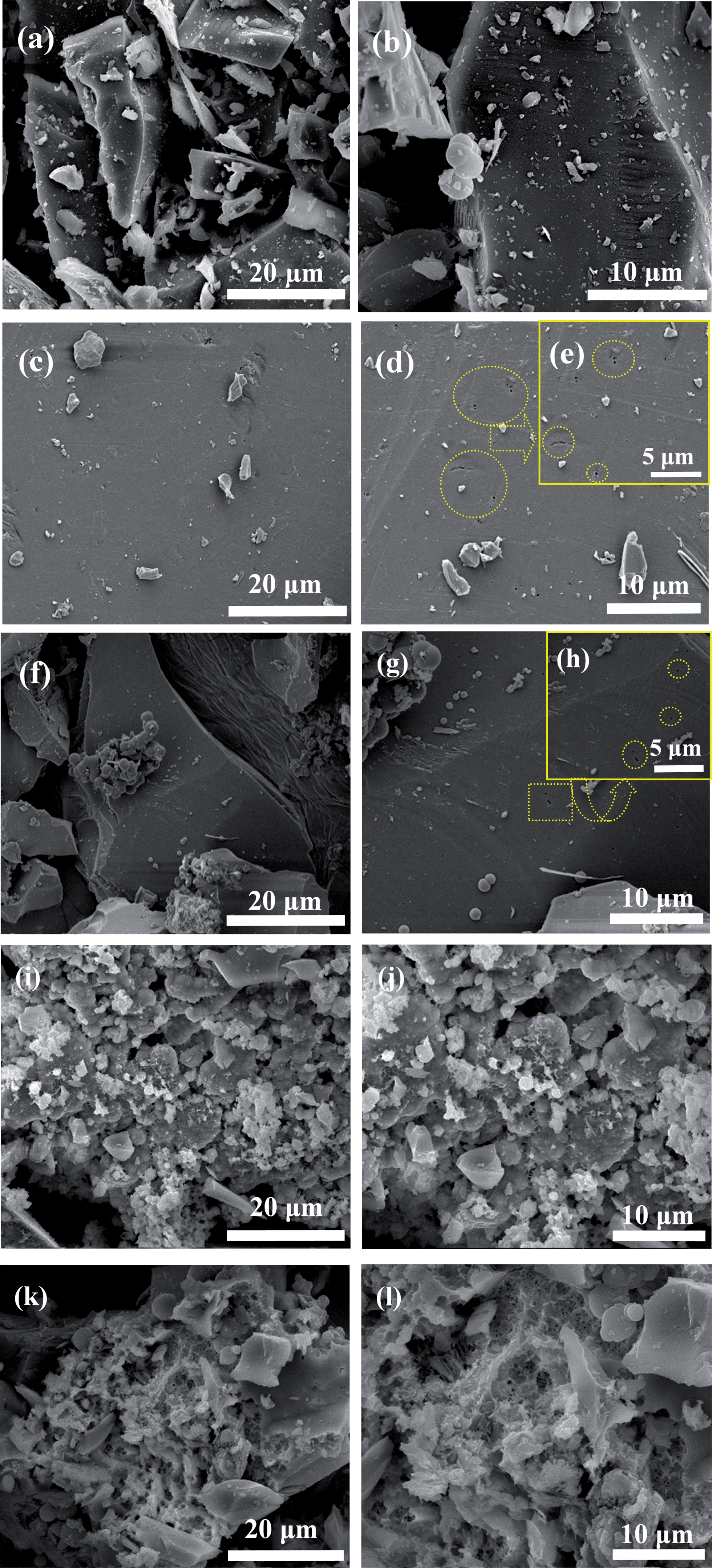 | ||
| Fig. 2 SEM images of SiCN (a and b), and the SiCN-5-HF composite (c–e), SiCN-10-HF composite (f–h), SiCN-15-HF composite (i and j), SiCN-20-HF composite (k and l). | ||
The EDX spectra and elemental content of the SiCN and the SiCN-10-HF material are shown in Fig. S1 of the ESI.† The percentage of carbon content in the SiCN-10-HF material is higher than that of the unetched SiCN, while the content of silicon, nitrogen and oxygen is relatively decreased in the material. From the SEM and EDX spectra, it is likely that some silicon-containing phases have been partly reacted with the HF solution in the etching process and removed from the SiCN matrix.
TEM images of the SiCN and SiCN-10-HF materials are shown in Fig. 3. It can be clearly seen that the nano-sized crystals are well-distributed in the structure of the SiCN-10-HF material (Fig. 3c). The carbon phase in the SiCN-10-HF material was amorphous. The crystal lattice of SiC is shown in both the SiCN and SiCN-10-HF materials (Fig. 3b and d), while the Si3N4 and graphite lattices are only exhibited in unetched SiCN, not in the SiCN-10-HF material, which indicated that the Si3N4 phase was removed by HF etching and the phase transformation of amorphous carbon. The etching chemical equation is as follows:27
| Si3N4 + 18HF = H2SiF6 + 2(NH4)2SiF6 | (1) |
 | ||
| Fig. 3 TEM images of SiCN (a and b) and SiCN-10-HF material (c and d). | ||
Additionally, as shown in Fig. 3d, many nano-sized holes are also dispersed on the base of the amorphous carbon in the SiCN-10-HF material, which can provide new channels for Li+ transfer. We think that both the nano-sized pores and the amorphous carbon can contribute to the improvement of the electrochemical properties of the HF-etched SiCN anode for lithium ion batteries. The following electrochemical tests (Fig. 6, 7, 9 and 10) can demonstrate this.
Fig. 4a shows the TGA analysis of the cross-linked SiCN polymer precursor. As indicated, the two temperature ranges at 100–170 °C and 400–750 °C correspond to the desorption of surface bound water, and the decomposition of organic groups and the carbon framework in the polymer-precursor, respectively. At the same time, the major weight loss of the cross-linked polymer precursor is 14.2 wt% in the range 400–800 °C upon pyrolysis. After heating at 1000 °C, all SiCN polymers are transferred into inorganic SiCN material.
 | ||
| Fig. 4 (a) TGA analysis of the cross-linked SiCN polymer precursor; (b) XRD patterns of the SiCN and SiCN-10-HF materials; (c) FTIR spectra of the SiCN and SiCN-x-HF materials; (d) BJH pore-size distribution plot of the SiCN-10-HF material. | ||
XRD patterns of the SiCN and SiCN-10-HF materials are shown in Fig. 4b. As shown, the diffraction peaks of the unetched SiCN material are broad, indicating an amorphous structure which corresponds with the SiCN structure previously reported.28 Compared with the pattern of the unetched SiCN, the XRD pattern of the SiCN-10-HF material exhibits no changes, which demonstrates that the amorphous structure of SiCN remains original and no new phase was formed during the HF etching process.
To further investigate the changes of internal bonds in SiCN and SiCN-x-HF materials, the FTIR spectra are employed (Fig. 4c). The distinct and broad absorption peaks of SiCN-x-HF located at around 3451, 896–690 and 461 cm−1 are attributed to the stretching vibrations of N–H, Si–C and Si–O respectively.13,22 In the FTIR spectra of the four SiCN-x-HF materials, the absorption peak of the Si–N bond at 1080 cm−1 are found in the FTIR spectra of both the SiCN-5-HF and SiCN-10-HF materials, and are absent in the SiCN-15-HF and SiCN-20-HF materials. Compared with unetched SiCN, the stretching vibration of the Si–C bond in SiCN-10-HF is strong and that of the Si–O bond is weak, indicating that Si–O bonds are more likely to be broken than Si–C bonds by HF etching. Also considering the TEM images, it is deduced that the Si3N4 phase and Si–O bond are removed during the etching process.
The pore size distribution curve of the SiCN-10-HF material (Fig. 4d), calculated from the adsorption branch by the BJH method, displays small pores with a typical size of 1–6.5 nm, which is consistent with the SEM and TEM images (Fig. 2g, h and 3d). The pore diameter of these nano-sized holes is much bigger than that of Li+ (0.076 nm), which can benefit the transportation of Li+ during charge and discharge process.
As shown in Fig. 5, XPS analysis is conducted to compare the element bonds in the unetched SiCN and SiCN-10-HF material. The C1s spectra for both the unetched SiCN and SiCN-10-HF can be decomposed into C![[double bond, length as m-dash]](https://www.rsc.org/images/entities/char_e001.gif) C or C–C, Si–C and C–O peaks. Compared with those in the unetched SiCN material, the size of the Si–C peak in SiCN-10-HF material increased and CC and C–C peaks decreased. In the Si2p spectra of the SiCN-10-HF material, there is no Si–N peak, and the size of the Si–C peak decreased while the Si–O peak increased, which indicated that HF may react with the bonds of Si3N4 to form compounds containing fluorine and silicon. The reaction equation is given in (1). A full survey of the XPS analyses of the unetched SiCN and SiCN-10-HF materials are shown in Fig. S2 of the ESI.† Table S1 in the ESI† illustrates the atomic percentage of elements on the surface of the unetched SiCN and SiCN-10-HF materials determined by XPS.
C or C–C, Si–C and C–O peaks. Compared with those in the unetched SiCN material, the size of the Si–C peak in SiCN-10-HF material increased and CC and C–C peaks decreased. In the Si2p spectra of the SiCN-10-HF material, there is no Si–N peak, and the size of the Si–C peak decreased while the Si–O peak increased, which indicated that HF may react with the bonds of Si3N4 to form compounds containing fluorine and silicon. The reaction equation is given in (1). A full survey of the XPS analyses of the unetched SiCN and SiCN-10-HF materials are shown in Fig. S2 of the ESI.† Table S1 in the ESI† illustrates the atomic percentage of elements on the surface of the unetched SiCN and SiCN-10-HF materials determined by XPS.
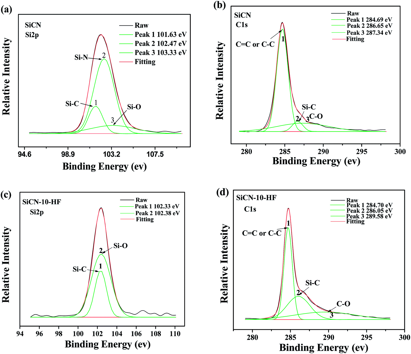 | ||
| Fig. 5 XPS analysis of unetched SiCN in the Si2p (a) and C1s (b), SiCN-10-HF in the Si2p (c) and C1s (d). | ||
The electrochemical performances of the HF-etched SiCN materials as anodes for Li ion batteries are shown in Fig. 6, 7, 9 and 10. Fig. 6 shows the charge and discharge potential curves versus capacity for the SiCN and SiCN-10-HF anodes at the first and second cycles. As shown, the charge and discharge potential plateaus of the SiCN-10-HF anode are evidently longer than that of unetched SiCN indicating higher charge and discharge capacities, which are advantageous for anode materials. In Fig. 6b, the discharge potential faint plateaus for the SiCN-10-HF anode in the first cycle are 1.5 V and 0.75 V. The 0.75 V plateau is attributed to the formation of the solid electrolyte interphase (SEI). The SEI is formed by the reaction of the electrode material and the electrolyte, and usually occurs on the electrode surface in the first charge–discharge cycle resulting in irreversible capacity. The formation of SEI carbon anode materials is about 0.7–0.8 V.29 However, there are no distinct discharge plateaus for the unetched SiCN anodes. Additionally, the charge–discharge potential curves of both the SiCN and SiCN-10-HF anodes display gentle slopes, which demonstrate the amorphous structures, consistent with their XRD patterns in Fig. 4b.
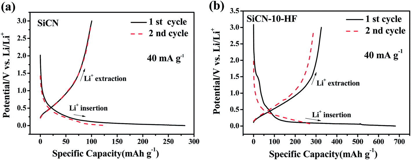 | ||
| Fig. 6 The capacity–potential curves of the 1st and 2nd cycles for SiCN (a) and SiCN-10-HF (b) anodes at a current density of 40 mA g−1. | ||
 | ||
| Fig. 7 (a) Cycle performances of SiCN and SiCN-x-HF (x = 5, 10, 15, 20) anodes at a current density of 40 mA g−1; (b) graphs of the coulombic efficiency vs. cycle number for the SiCN and SiCN-10-HF anodes; (c) the graphs of the discharge capacity vs. HF concentration for SiCN and SiCN-x-HF (x = 5, 10, 15, 20) at cycles 1, 2, 20, 50 and 100; (d) high-rate performances of SiCN and SiCN-10-HF anodes at different current densities of 40, 80, 190 and 380 mA g−1. | ||
Fig. 7a shows the cycle performances of the SiCN and SiCN-x-HF (x = 5, 10, 15, 20) anodes at a current density of 40 mA g−1. The initial specific discharge capacities of the HF-etched SiCN materials are 463, 681, 767 and 309 mA h g−1 respectively with increasing weight concentration of HF solution, all of which are much higher than for the unetched SiCN anode (282 mA h g−1). In all of the HF-etched SiCN materials, the SiCN-10-HF anode show the best cycle stability and reversible charge and discharge capacity. The first discharge capacity of the SiCN-10-HF anode (681 mA h g−1) is 2.4 times that of the unetched SiCN anode (282 mA h g−1). Although its discharge capacity decreases to 291 mA h g−1 in the second cycle, the discharge capacity remains stable above 300 mA h g−1 from the 3rd to 75th cycles. After 100 cycles, the discharge capacity of the SiCN-10-HF anode is still 229.3 mA h g−1, which is 5.0 times that of the unetched SiCN material (45.6 mA h g−1). The reason for the good electrochemical performance of SiCN-10-HF anode is that its electrode material cannot be pulverized severely after many charge–discharge cycles, which can be proved by SEM. The SEM images of the SiCN and SiCN-10-HF anodes before and after cycling are shown in Fig. 8 and S3 of the ESI.† From these, we can clearly see there are a lot of cracks in the SiCN material after several cycles' charge–discharge, however, there are hardly any cracks in the SiCN–HF material after the same number of charge–discharge cycles. The SEM evidence indicates that the SiCN anodes with HF-etching undergo less structural expansion during the charge–discharge process, which results in good cycle stability. Additionally, we can also see from Fig. 7a that the capacity and cycle stability of SiCN synthesized with high concentrations of HF during etching (SiCN-15-HF and SiCN-20-HF) are not good, because too many pores and holes in the SiCN matrix, which are etched by the HF solution, may lead to an unstable structure during the charge and discharge process.
 | ||
| Fig. 8 SEM images of the SiCN-10-HF anode before (a) and after (b) 100 charge–discharge cycles. | ||
Fig. 7b shows the coulombic efficiency of the unetched SiCN and SiCN-10-HF anodes at 1–100 charge–discharge cycles. Except for the first cycle, the coulombic efficiency of the SiCN-10-HF anode stays above 97%, and the average coulombic efficiency of the SiCN-10-HF anode is 99.50%, which is slightly higher than that of the unetched SiCN (98.15%) indicating that the HF etching benefits the coulombic efficiency of the SiCN anode.
Fig. 7c shows the graphs of the discharge capacity vs. HF concentration for the SiCN and SiCN–HF anodes in different cycles. From the graphs, we can see that to obtain excellent cycle stability and charge–discharge capacity, the optimized concentration of HF solution for etching is about 10 wt%, which indicates the SiCN with 10 wt% HF-etching may have the appropriate number and size of pores for Li+ transformation. The surface of SiCN cannot form enough Li+ transformation channels by etching with dilute concentrations (<10 wt%) of HF. The integrity of the SiCN matrix may be destroyed by etching with higher concentrations (>10 wt%) of HF.
The high-rate performances of the SiCN and SiCN-10-HF anodes at different current densities are exhibited in Fig. 7d. As shown, the SiCN-10-HF anode has a good electrochemical performance at high rates. The SiCN-10-HF electrode delivered a capacity of 355 mA h g−1 at a current density of 40 mA g−1, 270 mA h g−1 at 80 mA g−1, 160 mA h g−1 at 190 mA g−1, and 79 mA h g−1 at 380 mA g−1, respectively. Under the same conditions, the unetched SiCN electrode possessed a capacity of 175 mA h g−1 at 40 mA g−1, 122 mA h g−1 at 80 mA g−1, 40 mA h g−1 at 190 mA g−1, and 6.2 mA h g−1 at 380 mA g−1, all of which are lower than that of the SiCN-10-HF anode. From these results, it is demonstrated that HF etching can improve the high-rate capability of SiCN anodes. This is because the nano-holes formed by HF etching in the SiCN matrix can facilitate Li+ transportation during charge and discharge processes.
CV profiles of the SiCN and SiCN-10-HF anodes in the potential range between 0 and 3.0 V are shown in Fig. 10. In the first cycle, the peaks between 0.6–0.9 V for the SiCN anode (Fig. 9a) and 0.5–1.0 V for the SiCN-10-HF anode (Fig. 9b) are attributed to SEI formation on the electrode, which are consistent with the plateaus in the charge–discharge curves (Fig. 6). Except for the above peaks, there is no detectable peak in the CV curve, suggesting that no new phase was formed during lithium insertion and extraction. This indicates the capacity of the SiCN and SiCN-10-HF anodes continuously increases with the applied voltage, similarly to the results in the study of Chen et al. for SiCN anodes.30
 | ||
| Fig. 9 Cyclic voltammetry curves of SiCN (a) and SiCN-10-HF (b) anodes at a scan rate of 0.05 mV s−1. | ||
As shown in Fig. 10, EIS tests were carried out to evaluate the electrochemical kinetics properties of the SiCN and SiCN-10-HF anodes at 50% depth of discharge (DOD). The Nyquist plots for both electrodes consist of two semicircles and a straight line. The semicircle at high frequency may be ascribed to Li ion diffusion and charge separation via the “effective layers” (the unique microstructure of the anode material) at the SiCN interface and the other semicircle in the mid-frequency range is related to the regular charge transfer and double layer formation at the SiCN/electrolyte interface.15 The low frequency straight line (Warburg line) is attributed to Li ion diffusion in the electrolyte to the electrode interface. The smaller semicircle for the SiCN-10-HF anode indicates a lower electrochemical resistance than that of the unetched SiCN anode.30 The fitting results were attained using ZView from Sai software31 using an electrochemical model (equivalent circuit) shown in the inset of Fig. 10. Rs represents the sum of the ohmic resistance of the research system, including the ohmic resistance of the electrolyte, the electrode and the interface etc.; CPE1 and CPE2 (constant phase elements) represent the double layer capacitance and the SEI film capacitance instead of a capacitor to compensate for non homogeneity in the system; R1 and R2 are charge transfer resistors; and W0 is the finite Warburg length with a short circuit terminus. The parameters obtained by fitting are listed in Table 1. Compared with the EIS fitting data of unetched SiCN, the SiCN-10-HF anode demonstrated smaller R1 and R2 values and larger CPE1 and CPE2 values, which indicated faster electrochemical kinetics.
 | ||
| Fig. 10 EIS Nyquist plots of unetched SiCN and SiCN-10-HF anodes (inset figure is equivalent circuit for EIS data fitting). | ||
| Parameter | Unetched SiCN | SiCN-10-HF |
|---|---|---|
| Rs/Ω | 5.368 | 6.581 |
| R1/Ω | 233.6 | 201.0 |
| R2/Ω | 675.3 | 4.48 × 10⁻⁵ |
| CPE1-T/μF | 14.83 | 33.48 |
| CPE2-T/μF | 251.61 | 473.69 |
| W0 − R/Ω | 233.7 | 653.4 |
To summarize all of the above electrochemical tests, the SiCN-10-HF material synthesized by etching the dense SiCN powder exhibits high charge and discharge capacity, improved cycle stability and high-rate performance. There are two reasons to explain the improved electrochemical performance: firstly, the nano-sized pores or holes on the surface of SiCN-10-HF material not only offer new channels for the insertion and extraction of Li ions, but also alleviate the volume effect, resulting in improved cycling stability and good rate capability. Secondly, the HF etching of SiCN not only dissolves the silica phase which decreases the capacity decay of the Li–Si compound during charge–discharge cycles, but also relatively increases the carbon content in SiCN matrix which provides more active sites for Li+, resulting in the high charge and discharge capacities.
Although the irreversible capacity of the HF etched SiCN anode is satisfactory, the capacity decay between the first and second charge–discharge cycles is too much, and the coulombic efficiency is too low at the first cycle. These factors may be caused by the oxygen content in SiCN matrix. According to some literature,32 the high oxygen content in polymer-derived Si based materials is considered as a source for high irreversible capacity and significant hysteresis. It was found that excessive oxygen works as a trap for lithium ions during the first lithium insertion.33
Besides, to explain the lithium storage mechanism in the HF-etched SiCN anode, further studies involving nuclear magnetic resonance (NMR) should be employed, which are currently beyond the scope of our present work. However, by some deduction, we think that SiC and Si3N4 phases are the active sites for lithium storage while the interstitial spaces or edges between the graphene layers are also the major lithium storing sites. In order to prove these concepts we think further study should be performed using 29Si solid state NMR spectroscopy on the SiCN materials in order to learn more about the structural features of the anodes.
4. Conclusion
Porous polymer-derived SiCN materials were prepared by etching the silica phase of dense SiCN with 5–20 wt% HF solution. After HF etching, the surfaces of the SiCN materials become rough with 1–6.5 nm nano-sized pores, and the percentage content of carbon increased while the content of silicon, nitrogen and oxygen was relatively decreased in the material. Moreover, it is found that SiCN with 10 wt% HF etching (SiCN-10-HF) has the best electrochemical performance as an anode for lithium ion batteries. The initial charge–discharge capacity, the reversible discharge capacity and the high-rate performance of the SiCN-10-HF anode have been prominently improved. The improved electrochemical performances are mainly attributed to two reasons: the nano-sized holes caused by HF etching, which offer new channels for the insertion and extraction of Li ions and alleviate the volume expansion during the charge and discharge processes, and the HF etching of SiCN dissolving the Si3N4 and silica phases, which decreases the capacity decay of the Li–Si compound. Future work should be aimed at further investigating the charge–discharge mechanism of the HF-etched SiCN materials.Acknowledgements
The authors acknowledge financial support from the National Natural Science Foundation of China (no. 21103124), the Open Project Program of Tianjin Key Laboratory of Structure and Performance for Functional Molecules (no. 52XS1217), fund for outstanding young college teachers in Tianjin (no. ZX110QN047) and the Program for Innovative Research Team in Universities of Tianjin (no. TD12-5038).References
- J. B. Goodenough and K. Park, J. Am. Chem. Soc., 2013, 135, 1167–1176 CrossRef CAS PubMed.
- N. S. Choi, Z. Chen, S. A. Freunberger, X. Ji, Y. K. Sun, K. Amine, G. Yushin, L. F. Nazar, J. Cho and P. G. Bruce, Angew. Chew., Int. Ed., 2012, 51, 9994–10024 CrossRef CAS PubMed.
- M. Armand and J.-M. Tarascon, Nature, 2008, 451, 652–657 CrossRef CAS PubMed.
- J. R. Dahn, T. Zheng, Y. Liu and J. S. Xue, Science, 1995, 270, 590–593 CAS.
- M. N. Obroac and L. Christensen, Electrochem. Solid-State Lett., 2004, 7, A93–A96 CrossRef PubMed.
- M. Schmuck, A. Balducci, B. Rupp, W. Kern, S. Passerini and M. Winter, J. Solid State Electrochem., 2010, 14, 2203–2207 CrossRef CAS.
- M. Winter and J. O. Besenhard, Electrochim. Acta, 1999, 45, 31–50 CrossRef CAS.
- M. Wachtler, J. O. Besenhard and M. Winter, J. Power Sources, 2001, 94, 189–193 CrossRef CAS.
- I. A. Profatilova, C. Stock, A. Schmitz, S. Passerini and M. Winter, J. Power Sources, 2013, 222, 140–149 CrossRef CAS PubMed.
- G. Mera, A. Navrotsky, S. Sen, H. J. Kleebe and R. Riedel, J. Mater. Chem. A, 2013, 1, 3826–3836 CAS.
- S. Widgeon, G. Mera, Y. Gao, S. Sen, A. Navrotsky and R. Riedel, J. Am. Ceram. Soc., 2013, 96, 1651–1659 CrossRef CAS PubMed.
- R. Kolb, C. Fasel, V. Liebau-Kunzmann and R. Riedal, J. Eur. Ceram. Soc., 2006, 26, 3903–3908 CrossRef CAS PubMed.
- D. Su, Y. L. Li, Y. Feng and J. Jin, J. Am. Ceram. Soc., 2009, 92, 2962–2968 CrossRef CAS PubMed.
- M. Graczyk-Zajac, G. Mera, J. Kaspar and R. Riedel, J. Eur. Ceram. Soc., 2010, 30, 3235–3243 CrossRef CAS PubMed.
- J. Kaspar, G. Mera, A. P. Nowak, M. Graczyk-Zajac and R. Riedel, Electrochim. Acta, 2010, 56, 174–182 CrossRef CAS PubMed.
- M. Graczyk-Zajac, C. Fasel and R. Riedel, J. Power Sources, 2011, 196, 6412–6418 CrossRef CAS PubMed.
- Y. Chen, C. Li, Y. Wang, Q. Zhang, C. Xu, B. Wei and L. An, J. Mater. Chem., 2011, 21, 18186–18190 RSC.
- R. Bhandavat and G. Singh, ACS Appl. Mater. Interfaces, 2012, 4, 5092–5097 CAS.
- G. Liu, J. Kaspar, L. M. Reinold, M. Graczyk-Zajac and R. Riedel, Electrochim. Acta, 2013, 106, 101–108 CrossRef CAS PubMed.
- L. M. Reinold, M. Graczyk-Zajac, Y. Gao, G. Mera and R. Riedel, J. Power Sources, 2013, 236, 224–229 CrossRef CAS PubMed.
- M. Wilamowska, M. Graczyk-Zajac and R. Riedel, J. Power Sources, 2013, 244, 80–86 CrossRef CAS PubMed.
- Y. Feng, Electrochim. Acta, 2010, 55, 5860–5866 CrossRef CAS PubMed.
- Y. Feng, G. X. Du, X. J. Zhao and E. C. Yang, J. Appl. Electrochem., 2011, 41, 999–1002 CrossRef CAS.
- Y. Feng, N. N. Feng and G. X. Du, Int. J. Electrochem. Sci., 2012, 7, 3135–3140 CAS.
- Y. Feng, N. Feng, Y. Wei and Y. Bai, J. Mater. Chem. A, 2014, 2, 4168–4177 CAS.
- P. Dibandjo, M. Graczyk-Zajac, R. Riedel, V. S. Pradeep and G. D. Soraru, J. Eur. Ceram. Soc., 2012, 32, 2495–2503 CrossRef CAS PubMed.
- D. M. Knotter and T. J. J. Denteneer, J. Electrochem. Soc., 2001, 3, F43–F46 CrossRef PubMed.
- Y. F. Shi, Y. Wan, Y. P. Zhai, R. L. Liu, Y. Meng, B. Tu and D. Y. Zhao, Chem. Mater., 2007, 19, 1761–1771 CrossRef CAS.
- J. R. Dahn, T. Zheng, Y. H. Liu and J. S. Xue, Science, 1995, 270, 590–593 CAS.
- B. Wu, H. Song, J. Zhou and X. Chen, Chem. Commun., 2011, 47, 8653–8655 RSC.
- Y. Feng, Mater. Chem. Phys., 2010, 121, 302–307 CrossRef CAS PubMed.
- A. M. Wilson, W. Xing, G. Zank, B. Yates and J. R. Dahn, Solid State Ionics, 1997, 100, 259–266 CrossRef CAS.
- D. Larcher, C. Mudalige, A. E. George, V. Porter, M. Gharghour and J. R. Dahn, Solid State Ionics, 1999, 122, 71–83 CrossRef CAS.
Footnote |
| † Electronic supplementary information (ESI) available. See DOI: 10.1039/c4ra01086h |
| This journal is © The Royal Society of Chemistry 2014 |