Optimal design for a high performance H-JLTFET using HfO2 as a gate dielectric for ultra low power applications
Pranav Kumar Asthana*a,
Bahniman Ghoshab,
Shiromani Bal Mukund Rahia and
Yogesh Goswamia
aDepartment of Electrical Engineering, Indian Institute of Technology Kanpur, Kanpur 208016, India. E-mail: pranavasthan32@gmail.com
bMicroelectronics Research Center, University of Texas at Austin, 10100, Burnet Road, Bldg. 160, Austin, TX 78758, USA. E-mail: bghosh@utexas.edu
First published on 7th March 2014
Abstract
In this paper we have proposed an optimal design for a hetero-junctionless tunnel field effect transistor (TFET) using HfO2 as a gate dielectric. The device principle and performance are investigated using a 2D simulator. During this work, we investigated the transfer characteristics, output characteristics, transconductance, Gm, output conductance, GD, and C–V characteristics of our proposed device. Numerical simulations resulted in outstanding performance of the H-JLTFET resulting in ION of ∼0.23 mA μm−1, IOFF of ∼2.2 × 10⁻¹⁷ A μm−1, ION/IOFF of ∼1013, sub-threshold slope (SS) of ∼12 mV dec−1, DIBL of ∼93 mV V−1 and Vth of ≃0.11 V at room temperature and VDD of 0.7 V. This indicates that the H-JLTFET can play an important role in the further development of low power switching applications.
I. Introduction
Metal Oxide Semiconductor Field Effect Transistors (MOSFETs) present several challenges for sub-20 nm technology because of their steep doping profiles at source and drain junctions. Junctionless FETs provide a solution to this problem as they do not have doping junctions.1–3 They are also suited for high speed applications but their high subthreshold swing, as in Complementary Metal Oxide Semiconductors (CMOS), makes them power consuming devices. TFETs have received attention for low power applications because of their low subthreshold swing.4–7 However, the low ON current hinders them from many other high speed applications. Now, Junctionless Tunnel FETs (JLTFETs) are the subject of intensive studies in device research as they have a low subthreshold swing along with a higher ON current, giving a better speed.8,9 This device structure utilizes quantum tunneling using a charge plasma concept. Additionally, it does not have any doping junctions. It has established itself as one of the most promising candidates for future logic circuits, which operate at supply voltages smaller than 0.5 V. Moreover, the process budget is reduced because of the junctionless channel. Also, JLTFETs show better electrical performance and less variability than MOSFETs10 because there are no p–n junctions. In this paper we proposed and investigated a new structure, a H-JLTFET. This structure takes advantage of dual material channels causing higher tunneling in an ON state and reduced tunneling in an OFF state. As a result, there is a drastic improvement in performance. We have optimized our device structure using Silvaco TCAD Atlas 2D.II. Device structure and parameters
Fig. 1 shows the proposed device structure of the Si:Ge hetero-junctionless tunnel field effect transistors. An n+ Poly Gate and a p+ Poly Source are used to provide an appropriate work function difference between the gate and channel for the creation of p–i–n regions. The lower band gap material germanium on the source side causes higher tunneling in the ON state, while drain side tunnelling weakens because of the higher band gap material, silicon. There are many reports indicating successful attempts to fabricate Si and Ge interfaces.10,11 The parameters used in our simulations for Si:Ge H-JLTFET are: gate length = 20 nm, gate dielectric, HfO2 thickness (Tox) = 2 nm, Si:Ge film thickness (Tsi) = 5 nm, low-k spacer thickness = 2 nm, work function of the poly n+ region of the gate = 4.2 eV, work function of the poly p+ region of the gate = 5.3 eV, supply voltage = 0.7 V and carrier concentration in the uniformly doped channel ND = 1.0 × 1018 cm−3. The Si-TFET has the same parameters as Si:Ge H-JLTFET except for the channel with doping junctions, with a channel region doping concentration of 1016 cm−3 and source/drain doping concentration of 1018 cm−3. Similarly, the Si-JLTEFT has the same parameters, except a Si channel is used instead of a Si:Ge interface.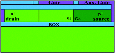 | ||
| Fig. 1 Cross sectional view of the device structure of the Si:Ge hetero-junctionless tunnel field effect transistor. | ||
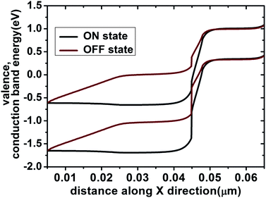
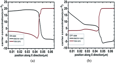
Fig. 2 shows the valence and conduction band energy profiles along the x-direction at the channel and HfO2 interface of the H-JLTFET shown in Fig. 1. It is observed that, in the OFF state, the tunneling barrier is too large, which causes a negligible tunneling probability of electrons. In the OFF state, only a small leakage current flows in the device. Fig. 3 shows the electron and hole charge concentration profiles along the x-direction at the channel and HfO2 interface of the H-JLTFET. From Fig. 3, it is observed that on applying the gate voltage on the control gate (named gate in our proposed structure, as shown in Fig. 1), the electron concentration beneath this gate increases. This result shows that the applied gate voltage causes lowering of the tunneling barrier between the source and channel. For a tunnel FET, it is found that the ON current increases exponentially with a decrease of the tunneling barrier.11 From Fig. 2, it can be noted that in the ON state, the barrier width is sufficiently lowered, causing an increase in the tunneling probability of electrons from the valence band to the conduction band, resulting in sufficient current flow in the device. Further use of a high-k gate dielectric material, HfO2, improves the gate control and hence the ON current and subthreshold slope. All simulations are done using SILVACO ATLAS 2D V5.15.32 R software.12 A drift-diffusion current transport model, Lombardi mobility model and SRH recombination model are used for simulations.12,13 Apart from that, a Band Gap Narrowing (BGN) model is used because of the highly doped channel,14 and a non-local band to band tunneling model is used to study the effect of tunneling.12 For further accuracy, Schenk’s Trap Assisted Tunneling (TAT) model and Quantum Confinement (QC) model are incorporated.12,15 Grid points are kept at 0.2 nm spacing in the x-direction and at 0.5 nm spacing in y-direction.
III. Results and discussions
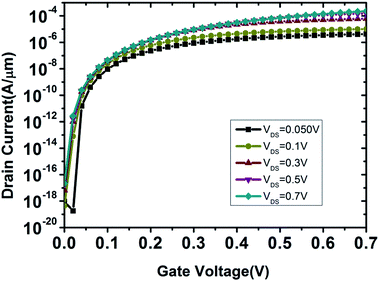
Fig. 4 shows a comparison of the ID–VG characteristics of our proposed device with the Si-JLTFET and Si-TFET with the same dimensional parameters. It can be observed that the proposed device has much better device characteristics than the other two. Further, ION, of 0.23 mA μm−1, 0.82 μA μm−1 and 0.08 μA μm−1; IOFF, of 2.2 × 10⁻¹⁷ A μm−1, 1.9 × 10⁻¹⁴ A μm−1 and 1.6 × 10⁻¹⁵ A μm−1; ION/IOFF, of 1013, 4.3 × 10⁷ and 5 × 10⁷ are observed for the H-JLTFET, JLTFET and TFET, respectively. The TFET has a lower OFF state current than the JLTFET, as the JLTFET has no physical junction but rather junctions created by charge plasma concept. However, the ON state current of the JLTFET is much higher than the TFET because of the inheritance of a junctionless FET. TFET and junctionless FET blended JLTFETs have significantly higher ION/IOFF than the TFET. The Si:Ge hetero-structure tremendously improves performance in comparison to the JLTFET, due to the increased band to band tunneling on the source side in the ON state. Fig. 4 clearly depicts that from the subthreshold slope to the ON and OFF state currents, the H-JLTFET has enhanced device characteristics. Transfer characteristics of the proposed device are shown in Fig. 5 for different drain voltages. This figure also indicates the drain induced barrier lowering which is highly suppressed. ‘X’ On Insulator (XOI) and junctionless FETs with highly controlled tunneling employing hetero-structures at very low voltages are the reason for the highly suppressed drain induced barrier lowering (DIBL). This result shows that our device works well for a wide range of applied voltages from 0.0 V to 0.7 V. DIBL is calculated from the following formula16
 | (1) |
 is the threshold voltage at VDS = 0.7 V. The H-JLTFET has a DIBL of 73 mV V−1. Also, a subthreshold slope of 12 mV per decade is calculated for VDS = 0.7 V and VGS = 0.7 V using the following formula
 | (2) |
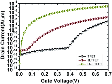 | ||
| Fig. 4 Comparison of the transfer characteristics of the Si-TFET, Si-JLTFET and Si:Ge H-JLTFET with the same dimensional parameters. | ||
The International Technology Roadmap for Semiconductors (IRTS) made predictions in 2013 that 22 nm High Performance (HP) will have ION of 2.2 mA μm−1 and IOFF of 0.37 μA μm−1, while 22 nm Low standby Power (LSTP) will have ION of 0.5 mA μm−1 and IOFF of 2 × 10⁻¹¹ μA μm−1.17,18 Clearly, the H-JLTFET surpasses both limits of both technologies.
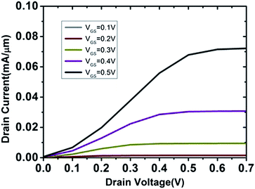
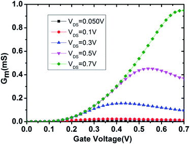
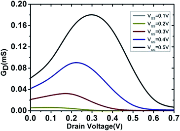
The output characteristics of the H-JLTFET for VGS ranging from 0.1 V to 0.7 V are shown in Fig. 6. We observed an exponential increase in the drain current with increasing gate voltage, demonstrating better gate control. Also, the saturation region is flatter, indicating negligible channel length modulation. Besides, other short channel effects reported previously, especially the kink effect, are highly suppressed.19,20 Fig. 7 shows transconductance as a function of gate voltage for VDS ranging from 0.05 V to 0.7 V. The transconductance obtained for the gate voltage resembles the conventional curve at lower gate voltages. However, deviation is observed for higher values of gate voltage, as tunneling is a nonlinear phenomena and depends on the orientations of the band structure. Similarly, output conductance,  characteristics are compiled in Fig. 7 for VGS ranging from 0.1 to 0.7 V. A hump is observed in GD around VGS/2 due to Drain Induced Tunneling (DIT). At high VGS and low VDS, a small increase in VDS causes more tunneling. Hence, the drain voltage mimics the behaviour of the gate voltage at low VDS, but for VDS > VGS/2 DIT fades as the rate of tunneling decreases and hence transconductance follows conventional behaviour afterwards (Fig. 8).
Fig. 9(a) and (b) show a comparison of the gate-to-drain and gate-to-source capacitance, respectively, for the H-JLTFET and JLTFET as a function of the gate voltage at a drain voltage of 0.7 V, with a frequency of 1 MHz and a small signal voltage of 0.01 V. The JLTFET provides a gate-to-drain/source capacitance that is a little lower than the H-JLTFET at higher gate voltages.
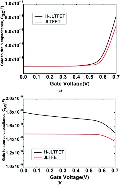 | ||
| Fig. 9 Variation of (a) gate-to-drain capacitance, CGD and (b) gate-to-source capacitance, CGS, with a gate voltage at VDS = 0.7 V, frequency = 106 Hz and vss = 0.01 V for the H-JLTFET. | ||
IV. Conclusions
In this work, we proposed an optimal design of a Hetero-Junctionless Tunnel Field Effect Transistor (H-JLTFET) using HfO2 as a gate dielectric and discussed its static operation. Through simulation, we also studied the characteristics of the H-JLTFET, especially for switching applications. The device provides high speed operation even at very low supply voltages, with low leakage and a reduced number of steps in the fabrication process, which indicates that the H-JLTFET is a promising candidate for switching performance. In addition, it has the potential for further scalability.References
- J.-P. Colinge, C.-W. Lee, A. Afzalian, N. D. Akhavan, R. Yan, I. Ferain, P. Razavi, B. O'Neill, A. Blake, M. White, A.-M. Kelleher, B. McCarthy and R. Murphy, Nanowire transistors without junctions, Nat. Nanotechnol., 2010, 5(3), 225–229 CrossRef CAS PubMed
.
- C.-W. Lee, A. Afzalian, N. D. Akhavan, R. Yan, I. Ferain and J.-P. Colinge, Junctionless multigate field-effect transistor, Appl. Phys. Lett., 2009, 94(5), 053511–053512 CrossRef PubMed
.
- C.-W. Lee, I. Ferain, A. Afzalian, R. Yan, N. Dehdashti Akhavan, P. Razavi, J. Pierre and L. Maltings, Performance estimation of junctionless multigate transistors, Solid-State Electron., 2010, 54(2), 97–103 CrossRef CAS PubMed
.
- K. Boucart and A. M. Ionescu, Double gate tunnel FET high K gate dielectric, IEEE Trans. Electron Devices, 2007, 54, 7 CrossRef
.
- A. M. Ionescu and H. Riel, Tunnel field-effect transistors as energy-efficient electronic switches, Nature, 2011, 479, 329 CrossRef CAS PubMed
.
- K. Boucart, Length scaling of the Double Gate Tunnel FET with a high-K gate dielectric, Solid-State Electron., 2007, 51, 1500 CrossRef CAS PubMed
.
- K. Boucart, A new definition of threshold voltage in Tunnel FETs, Solid-State Electron., 2008, 52, 1318 CrossRef CAS PubMed
.
- B. Ghosh and M. W. Akram, Junctionless Tunnel Field Effect Transistor, IEEE Electron Device Lett., 2013, 34(5), 584–586 CrossRef CAS
.
- B. Ghosh, P. Bal and P. Mondal, A junctionless tunnel field effect transistor with low subthreshold slope, J. Comput. Electron., 2013, 12, 428 CrossRef CAS
.
- J. Xiang, Ge/Si nanowire heterostructures as high performance field-effect transistors, Nature, 2006, 441, 489 CrossRef CAS PubMed
.
- W. Lu, J. Xiang, B. P. Timko, Y. Wu and C. M. Lieber, One-dimensional hole gas in germannium/silicon nanowire heterostructures, Proc. Natl. Acad. Sci. U. S. A., 2005, 102, 10046 CrossRef CAS PubMed
.
- ATLAS Device Simulation Software, Silvaco Int., Santa Clara, CA, USA, 2012 Search PubMed
.
- A. Schenk, A model for the field and temperature dependence of SRH lifetimes in Silicon, Solid-State Electron., 1992, 35, 1585 CrossRef CAS
.
- A. Schenk, Finite-temperature full random-phase approximation model of band gap narrowing for silicon device simulation, J. Appl. Phys., 1998, 84, 7 Search PubMed
.
- W. Hansch, Th. Vogelsang, R. Kirchner and M. Orlowski, Carrier Transport Near the Si/SiO2 Interface of a MOSFET, Solid-State Electron., 1989, 32, 839 CrossRef
.
- M. J. Kumar and M. Siva, IEEE Trans. Electron Devices, 2008, 55, 1554 CrossRef CAS
.
- ITRS roadmap, http://www.itrs.netaccessed on 18 September 2013 Search PubMed
.
- C. Calvin Hu, Modern Semiconductor Devices for Integrated Circuits, Pearson, India, 1st edn, 2010, pp. 279–280 Search PubMed
.
- J. G. Shaw and M. Hack, Simulations of short-channel and overlap effects in amorphous silicon thin-film transistors, J. Appl. Phys., 1989, 65(5), 2124–2129 CrossRef CAS PubMed
.
- D. Chung, B.-D. Choi and S.-G. Park, A New Model for Kink-Effect in Poly-Silicon Thin-Film Transistors, ASID, 2006 Search PubMed
.
| This journal is © The Royal Society of Chemistry 2014 |

