Improvement of electrochemical performance of rechargeable lithium–selenium batteries by inserting a free-standing carbon interlayer

Zhian Zhang*, Zhiyong Zhang, Kai Zhang, Xing Yang and Qiang Li
School of Metallurgy and Environment, Central South University, Changsha 410083, China. E-mail: zza75@163.com; Fax: +86 731 88830649; Tel: +86 731 88830649

Received 16th January 2014 , Accepted 14th March 2014

First published on 17th March 2014


Abstract

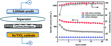
A simple, low-cost modification of lithium–selenium (Li–Se) cells by placing a carbon interlayer between the selenium electrode and the separator has been investigated to significantly improve the electrochemical performance of Li–Se cells.

Lithium–sulfur (Li–S) batteries have been studied as one of the most promising systems for the next generation high-energy rechargeable lithium batteries because of their high theoretical specific capacity (1675 mA h g−1) and energy density (2600 W h kg−1).1–3 Li–S batteries suffer from the low conductivity of S and the solubility of polysulfide species during cycling.4–7 As a congener of sulfur, selenium being electrochemically similar to sulfur can be expected to react with lithium to generate selenides. Although the theoretical gravimetric capacity of the selenium (675 mA h g−1) is lower than that of sulfur (1672 mA h g−1), the theoretical volumetric capacity of selenium (3253 mA h cm−3 based on 4.82 g cm−3) is comparable to that of sulfur (3467 mA h cm−3 based on 2.07 g cm−3). In addition, selenium has 20 orders of magnitude higher electrical conductivity than sulfur.8–13 The advantages of Se make it a prospective candidate for cathode material in high energy density lithium batteries for specific applications. However, at present, research on lithium–selenium (Li–Se) batteries is still at a very early stage. Similar to sulfur, the selenium cathodes also face the dissolution issue of high-order polyselenides, resulting in fast capacity fading, poor cycle performance and low Coulombic efficiency.9,10

Recently, several efforts have been made to improve the electrochemical performance of Li–Se batteries, just like the same strategies in Li–S batteries. One effective strategy is confining selenium within various forms of porous matrixes, such as porous carbon,8,10,11 graphene.13 Abouimrane et al.8 conducted pioneering work on the use of Se–C composite as a cathode material. The Li/Se system sustained a reversible capacity of ∼300 mA h g−1 at a low current density (50 mA g−1, ∼C/12) after 100 cycles, demonstrating the excellent cycle life of this system. Guo et al.11 synthesized the selenium–carbon composite through a facile melt-diffusion process from a ball-milled mixture of CMK-3 and Se. The Se/C cathode exhibited excellent cycling stability with a discharge capacity of 600 mA h g−1 at current density of 67 mA g−1 (0.1 C) after 50 cycles. As discussed, the major stream of the Li–Se battery research has focused on the modification ‘inside’ of the cathode, but the design ‘outside’ of the cathode, such as cell configuration, could be a new strategy for improving the performance of the Li–Se batteries. Carbon layer material has been reported that has great effect on the electrochemical performance for batteries14–17.

In this study, we present a cheap and simple, but markedly effectively solution by inserting a conductive, porous carbon interlayer between the cathode and the separator for Li–Se batteries. The free-standing carbon interlayer was fabricated easily by carbonizing cellulose based filter paper commonly used in laboratories. Characterizations of the carbon interlayer are given in ESI. Raman spectra (Fig. S1) reveals the existence of graphitized carbon after pyrolysis. TGA shows that the carbon interlayer only remains 5 wt% of cellulose based filter papers after the pyrolysis process (Fig. S2). N2 absorption–desorption isotherm of the carbon interlayer (Fig. S3) suggests that the BET surface area and BJH pore size are 534 m2 g−1 and 4.1 nm. Meanwhile, we choose Se/TiO2 composite prepared by melt-infiltration method as the cathode material based on our previous research work.18 The specific capacity and cycle performance of Li–Se batteries with carbon interlayer are significantly enhanced with a reversible capacity of 520 mA h g−1 after 20 cycles at a current density of 67.5 mA g−1.

Fig. 1a shows the cyclability profile of the Li–Se cells with and without the insertion of carbon interlayer. It can be seen that the capacity of both the Li–Se cells decrease with an increased number of cycles. With the carbon interlayer, the initial discharge capacity of the cell is 656.8 mA h g−1, which is 97.3% of the theoretical capacity of selenium, and it is much higher than that of the raw Li–Se cell (481.8 mA h g−1). The Li–Se cell with the carbon interlayer also exhibits excellent cycling stability, with the specific capacity remaining high at 520 mA h g−1 after the 20th cycle at a current density of 67.5 mA g−1 (C/10, C = 675 mA g−1). In contrast, the raw Li–Se cell shows only 199 mA h g−1 after 20 cycles under the same cycling conditions. However, the cell using the carbon interlayer as cathode cannot deliver any capacity under the same cycling conditions. The cell with carbon interlayer shows high Coulombic efficiency of nearly 99% after 20 cycles, consistent to the previous reports,10,11 which is higher than that of the raw Li–Se cell. The electrochemical characteristic of the cells with and without carbon interlayer was examined by cyclic voltammetry in the voltage range of 1.0–3.0 V with a scanning rate of 0.2 mV s−1, as shown in Fig. 1b. Two obvious cathodic peaks and one anodic peak can be observed, which are consistent with the previous report.9 The cathodic peaks at around 1.95 V and 2.15 V correspond to the conversion of elemental selenium into selenides, while the anodic peak at around 2.35 V can be assigned to the conversion of selenides into elemental selenium.9,10 Note that the reduction and oxidation peaks of the cell with carbon interlayer are much sharper than those of the cell without carbon interlayer, besides, the voltage gap (ΔE) between oxidation and reduction peaks for the cell with carbon interlayer is smaller than that of the cell without carbon interlayer. It indicates that the cell with carbon interlayer has better electrochemically reversibility, considering that the ΔE is determined by the polarization of the active material during the charge and discharge process.19


image file: c4ra00446a-f1.tif
Fig. 1 Electrochemical data of the Li–Se cells: cyclability and Coulombic efficiency of the cells at C/10 rate (a), CV plots of the cells with and without carbon interlayer (b), the discharge–charge profiles of the cells with (c) and without (d) carbon interlayer at C/10 rate, Nyquist plots for the Li–Se cells with and without carbon interlayer before cycling (e) and after 20th cycle (f).

In order to gain further insight on the electrochemical performance of the cells, galvanostatic discharge–charge test was carried out at the current density of 67.5 mA g−1 between 1.2 V and 3 V. Galvanostatic discharge–charge voltage profiles of the cells with carbon interlayer and without carbon interlayer are shown in Fig. 1c and d, respectively. Consistent with the result of cyclic voltammetry measurement, two discharge plateaus are exhibited in discharge curves for both of the Li–Se cells, which can be ascribed to the two step reaction of elemental selenium with metallic lithium during the discharge process.8 It is found that the cell with carbon interlayer shows more complete and stable plateaus at 2.15 V and 1.95 V. Besides, the smaller potential separation between the charge and discharge plateaus indicates better kinetic characteristics of the cell with carbon interlayer.19

To analyse the impact of the carbon interlayer in Li–Se batteries, electrochemical impedance spectroscopy (EIS) analysis was carried out. Fig. 1e and f present the Nyquist plots of the cells with and without carbon interlayer before the first discharge and after 20 cycles, respectively. The impedance plots are composed of a depressed semicircle at high frequency, and an inclined line at low frequency, similar to the previous literature.9,12 The diameter of the semicircle corresponds to the charge transfer resistance (Rct) of the cell which is mainly generated at the interface between the electrode and the electrolyte. In addition, the inclined line at low frequency reflects the Li ion diffusion into the active mass. It can be seen in Fig. 1e that the charge transfer resistance of the cell decreases by about 22% after the insertion of the carbon interlayer. In addition, the charge transfer resistance of both cells decreases after 20 cycles. Here, the carbon interlayer for the Se/TiO2 cathode, can provide efficient electron migration pathways to and from the active material, enhancing the active material utilization and thereby raising the specific capacity of the cell.

To further investigate the reason that a simple porous interlayer can considerably advance the electrochemical performance of the Li–Se cells, scanning electron microscope (SEM) analysis was carried out on cycled carbon interlayer. The microstructure images of the carbon interlayer with a porous structure are shown in Fig. 2a and c. The carbon interlayer made of tortuous carbon fibers allows the electrolyte permeate through it to react with the active material. The appearance of the carbon interlayer after 20 cycles (Fig. 2b and d) shows deposited materials on the surface of it. Magnified SEM image of the cycled carbon interlayer and elemental mapping are shown in Fig. 2e and f, respectively. It can be seen that the carbon interlayer is covered by a layer of deposited materials and the mapping indicates that the coating on the cycled carbon interlayer is rich in selenium. Besides, TEM of the carbon interlayer after cycling (Fig. S4) shows that the Se nanoparticles can be clearly seen on the carbon interlayer, corresponding to the result of SEM. It is believed that the polyselenides diffusing into the carbon interlayer are converted to selenide upon discharging.10 The carbon interlayer acts as a matrix to capture and retain the polyselenides by electrochemical deposition at the end of discharge–charge process. The deposition in carbon interlayer reduces the loss of active material, leading to a superior re-utilization of the active material and improved cycle life.


image file: c4ra00446a-f2.tif
Fig. 2 Morphology of the carbon interlayer: (a) and (c) before cycling, (b), (d) and (e) after 20 cycles at C/10 rate, and (f) elemental mapping of (e).

The Li–Se battery with carbon interlayer also performs well in high rate applications. It can be seen that the specific capacity of all the cells decreases with the increasing cycles. However, the cell with carbon interlayer can keep a higher specific capacity. At the discharge–charge rate of C/5, the cell with carbon interlayer maintains high capacity of 282 mA h g−1 after 100 cycles, which is more than twice that of the raw Li–Se cell (Fig. 3a). It can be seen in Fig. 3b that the cell with carbon interlayer delivers almost twice as much as the capacity of the raw Li–Se battery at the rate of C/2 after 100 cycles. Our design greatly enhances the rate performance of lithium–selenium cells. The conductive carbon interlayer effectively promotes rapid electrochemical reactions in Li–Se batteries due to the decreasing interfacial resistance and abundant reaction sites introduced from the carbon interlayer.20–22 As a result, the insertion of carbon interlayer is a facile configuration modification in Li–Se batteries to improve the rate capability.


image file: c4ra00446a-f3.tif
Fig. 3 Rate performance of the Li–Se cells with and without the carbon interlayer: at a current density of C/5 (a), at a current density of C/2.

In conclusion, the novel configuration of inserting a free-standing carbon interlayer into the Li–Se battery significantly enhances both the specific capacity and cycle stability. The conductive carbon interlayer not only reduces the charge transfer resistance of Se/TiO2 cathodes significantly, but also captures the migrating active material during the discharge–charge processes. The increased electrical conductivity promotes efficient active material utilization and stable high rate battery performance with long cycle life. In addition, the porous carbon interlayer offers the advantage of serving as an excellent matrix to retain and accommodate dissolved intermediate polyselenides. The design of inserting a conductive carbon interlayer into Li–Se batteries is a feasible new approach, and we believe the work reported here may contribute to the development of Li–Se batteries in the future.

Acknowledgements

The authors acknowledge the financial supports from Teacher Research Fund of Central South University (2013JSJJ027).

Notes and references

  1. R. Noorden, Nature, 2013, 498, 416 CrossRef PubMed.
  2. Y. Yang, G. Zheng and Y. Cui, Chem. Soc. Rev., 2013, 42, 3018 RSC.
  3. S. Evers and L. Nazar, Acc. Chem. Res., 2013, 46, 1135 CrossRef CAS PubMed.
  4. M. Oschatz, S. Thieme, L. Borchardt and M. Lohe, Chem. Commun., 2013, 49, 5832 RSC.
  5. G. Zheng, Y. Yang, J. J Cha, S. S. Hong and Y. Cui, Nano Lett., 2011, 11, 4462 CrossRef CAS PubMed.
  6. M. Hagen, S. Dorfler, H. Alehues, J. Tubke, M. Hoffmann and S. Kaskel, J. Power Sources, 2012, 213, 239 CrossRef CAS.
  7. Y. Qu, Z. Zhang, X. Wang, Y. Lai, Y. Liu and J. Li, J. Mater. Chem. A, 2013, 1, 14306 CAS.
  8. A. Abouimrane, D. Dambournet, K. Chapman, P. Chupas, W. Weng and K. Amine, J. Am. Chem. Soc., 2012, 134, 4505 CrossRef CAS PubMed.
  9. Y. Cui, A. Abouimrane, J. Lu, T. Bolin, Y. Ren, W. Weng, C. Sun, V. Maroni, S. Heald and K. Amine, J. Am. Chem. Soc., 2013, 135, 8047 CrossRef CAS PubMed.
  10. C. Luo, Y. Xu, Y. Zhu, Y. Liu, S. Zheng, Y. Liu, A. Langrock and C. Wang, ACS Nano, 2013, 7, 8003 CrossRef CAS PubMed.
  11. C. Yang, S. Xin, Y. Yin, H. Ye, J. Zhang and Y. Guo, Angew. Chem. Int. Ed., 2013, 52, 1 CrossRef.
  12. L. Liu, Y. Hou, S. Xiao, Z. Chang, Y. Yang and Y. P. Wu, Chem. Commun., 2013, 49, 11515 RSC.
  13. D. Kundu, F. Krumeich and R. Nesper, J. Power Sources, 2013, 236, 112 CrossRef CAS.
  14. Y. Su, S. Li, D. Wu, F. Zhang, H. Liang, P. Gao, C. Cheng and X. Feng, ACS Nano, 2012, 6, 8349 CrossRef CAS PubMed.
  15. K. Gao, Z. Shao, X. Wang, Y. Zhang, W. Wang and F. Wang, RSC Adv., 2013, 3, 15058 RSC.
  16. S. Li, D. Wu, C. Cheng, J. Wang, F. Zhang, Y. Su and X. Feng, Angew. Chem. Int. Ed., 2013, 52, 12105 CrossRef CAS PubMed.
  17. C. Cheng, S. Li, J. Zhao, X. Li, Z. Liu, L. Ma, X. Zhang, S. Sun and C. Zhao, Chem. Eng. J., 2013, 228, 468 CrossRef CAS.
  18. Q. Li, Z. Zhang, K. Zhang, L. Xu, J. Fang, Y. Lai and J. Li, J. Solid State Electrochem., 2013, 17, 2959 CrossRef CAS.
  19. W. Bao, Z. Zhang, C. Zhou, Y. Lai and J. Li, J. Power Sources, 2014, 248, 570 CrossRef CAS.
  20. C. Zu, Y. Su, Y. Fu and A. Manthiram, Phys. Chem. Chem. Phys., 2013, 15, 2291 RSC.
  21. Y. Su and A. Manthiram, Chem. Commun., 2012, 48, 8817 RSC.
  22. Y. Su and A. Manthiram, Nat. Commun., 2012, 3, 1166 CrossRef PubMed.

Footnote

Electronic supplementary information (ESI) available: Detailed experimental. See DOI: 10.1039/c4ra00446a

This journal is © The Royal Society of Chemistry 2014
Click here to see how this site uses Cookies. View our privacy policy here.