Synthesis of metal nanoparticle@graphene hydrogel composites by substrate-enhanced electroless deposition and their application in electrochemical sensors

Can Dua, Zhiyi Yaob, Yunqiang Chena, Hua Bai*a and Lei Li*a
aCollege of Materials, Xiamen University, Xiamen, 361005, P. R. China. E-mail: baihua@xmu.edu.cn; lilei@xmu.edu.cn
bKey Laboratory for Biomedical Effects of Nanomaterials & Nanosafety, Institute of High Energy Physics, Chinese Academy of Sciences, Beijing, 100049, P. R. China

Received 24th December 2013 , Accepted 20th January 2014

First published on 23rd January 2014


Abstract

In this paper, a green and facile method based on substrate-enhanced electroless deposition is designed for the fabrication of three-dimensional (3D) metal nanoparticle@graphene hydrogel (MNP@GHG) composites. A galvanic cell was constructed by inducing nickel foam as the substrate of GHG, to enhance the deposition of MNPs via galvanic cell reaction. Various MNPs with redox potential higher than that of Ni, including Au, Pt, Pd and Cu, were successfully deposited onto GHG. The produced gold nanoparticles/GHG composite showed good electrocatalytic activity and was used to fabricate an amperometric sensor towards uric acid with good sensitivity.

Introduction

Graphene, a two-dimensional (2D) member of carbon nanomaterials, has attracted intense interests in recent years, owing to its large surface area,1 excellent thermal and electric conductivity,2,3 great mechanical strength4 and potential low manufacturing cost.5 These unique properties make graphene highly promising in diverse areas, including sensors,6,7 electronics and opotoelectronics,8–10 energy conversion and storage11–13 and environmental science.14,15 In many of these applications, graphene is used as a component of functional composites, which show superior performance to pristine graphene. Graphene decorated with metal nanoparticles (MNPs) is one important class of the graphene composites, which have distinguished themselves as excellent catalysts, either in chemical reactions and electrode processes. Many approaches, including self-assemble,16–19 electrochemical deposition12 and electroless deposition with the aid of reducing agents,20–24 have been devised to synthesize MNP/graphene composites. Among these approaches, the electroless deposition is of great interest because of its simplicity and effectiveness of regulating the size and shape of MNPs. However, the reducing agents commonly used for the preparation of MNP/graphene composites, such as hydrazine hydrate and NaBH4, are toxic or expensive. Moreover, residue of these agents in the MNP/graphene composites could have detrimental effect, especially in bio-related applications.

Recently, some environmentally friendly methods, such as microwave,25–27 ultrasound28 or illumination29 induced reduction of metal ions, have been used in the preparation of MNP/graphene composites. Besides, reduced graphene oxide (rGO), a typical chemically converted graphene, is a weak reducing agent with redox potential of +0.38 V vs. SHE (standard hydrogen electrode. All the redox potentials are versus SHE unless otherwise stated), thus gold nanoparticles can spontaneously grow on rGO sheets when rGO contacts with tetrachloroaurate salt solution (AuCl4/Au, +1.002 V)30 without any additional reducing agents.31 However, such process is slow and inefficient, and not applicable to those metal salts with low standard potential. As a modification of the direct-reduction method, substrate-enhanced electroless deposition (SEED) was designed, and successful in depositing MNPs with low redox potential onto carbon nanotubes (CNTs).32 To carry out SEED, a galvanic cell was constructed by depositing CNTs onto a substrate of active metal (Cu or Zn), and soaking them in the solution of noble metal salt. A galvanic cell reaction then occurs in which the active substrate is oxidized while the reduction of metal salts takes place on the inert CNTs, forming MNPs. In SEED process no toxic reducing agents is used, and the formed MNPs are not decorated with any organic ligand or stabilizer. Furthermore, galvanic cell reaction is much faster than the corresponding direct redox reaction. Thus SEED is a fast and eco-friendly method for deposition of MNPs. SEED has been used to deposit MNPs on rGO film.33 However, only the surface of the rGO film was successfully decorated with MNPs, because the aggregation of rGO sheets limited the diffusion of ion solution in the rGO film. Besides, the specific surface area of the resulted composite material was small, due to the aggregation of rGO sheets. The large specific surface area are crucial for many application. Therefore, it is necessary to develop new SEED method to efficiently prepare MNP/rGO composites.

Here in this paper, we successfully developed a universal approach based on SEED to prepare MNP/rGO three-dimensional (3D) composites. Porous nickel foam (NF) was induced as the substrate, on which graphene hydrogel (GHG) was deposited.34 GHG is in good electric contact with NF, and its 3D porous structure allows a rapid diffusion of electrolyte inside it, and make sure that most rGO sheets can contact with the electrolyte. Therefore, when GHG@NF was immersed in solution of metal salt, MNPs was deposited on the 3D rGO framework of GHG via galvanic cell reaction, yielding MNP@GHG composites. The metal with a redox potential higher than Ni (Ni2+/Ni, −0.257 V),30 including Au, Pt, Pd and Cu, were all successfully deposited on GHG through our approach. In addition, we also demonstrated that MNP@GHG composites combine the large surface area and high electric conductivity of the graphene with the high electrocatalysis activity of MNPs, thus become good electrode materials for electrochemical sensors.

Experimental

Chemicals and materials

Natural graphite powders were bought from Qingdao Huatai lubricant sealing S&T Co. Ltd. (Qingdao, China). Chloroauric acid, chloroplatinic acid, chloropalladic acid, copper chloride, cobalt nitrate, ferrous sulfate, zinc acetate, sodium ascorbate, sodium chloride, and sulfuric acid were purchased from Sinopharm Chemical Reagents Co. Ltd. (Beijing, China). Uric acid was the product of Alfa Aesar. Phosphate buffer solution (PBS, 0.1 M, pH = 7.4) was prepared dissolving NaH2PO4, Na2HPO4 and NaCl in deionized water. All the chemicals were used as received without further purification.

Preparation of GHG@NF

GO was prepared from natural graphite powder with the modified Hummers method,35,36 and GHG was prepared by chemically reducing GO dispersion with sodium ascorbate.37 Briefly, 5 mL GO aqueous dispersion (2 mg mL−1) containing 6 mg mL−1 sodium ascorbate was loaded in a 15 mL glass vial, into which a piece of NF (1 × 2 × 0.2 cm3) was added. The system was treated with sonication for 10 min to ensure the successful filling of GO suspension into the pores of NF. Successively, the as-prepared dispersion was heated at 90 °C for 1.5 h, and NF was completely covered by black GHG. The excess GHG on the surface of BF was removed with a knife, giving GHG@NF composite. The sodium ascorbate and other impurities in GHG@NF were then removed by dialysis.

Preparation of MNP@GHG composites

To prepare MNP@GHG composites, GHG@NF was immersed in different metal ion solutions (4 mM), including HAuCl4, H2PtCl6, H2PdCl4, CuCl2, for different periods of time. The obtained composites were rinsed by 20 mL deionize water and stored in deionized water.

Preparation of AuNP@GHG composite modified electrodes

The gold nanoparticle/GHG (AuNP@GHG) composites were exfoliated from NF into deionized water by ultrasonical treatment, forming AuNP@GHG suspension. A glassy carbon electrode (GCE, with diameter of 3 mm) was polished successively with 0.5 and 0.05 μm alumina slurry until a mirror finish was obtained and then cleaned ultrasonically in ethanol and water for 3 min, respectively, to remove the alumina residues. The cleaned GCE was dried with high-purity nitrogen steam. 10 μL of AuNP@GHG composite dispersion was dropped onto GCE and dried under 70 °C.

Characterization

Scanning electron micrographs (SEMs) were recorded on a LEO 1530 scanning electron microscope operated at 20 kV. TEM measurements were performed with a JEM2100 at an acceleration voltage of 200 kV. To prepare the TEM samples, lyophilized samples were soaked in ethanol and sonicated for 10 minutes; afterwards a small drop of suspension was deposited onto a carbon-coated copper electron microscopy (EM) grid and dried at room temperature. All the electrochemical experiments were carried out on CHI 660 electrochemical workstation in 0.1 M PBS solution with a conventional three-electrode system comprising a bare or modified GC electrode as the working electrode, a platinum sheet (1 cm × 1 cm) as the counter electrode, and saturated calomel electrode (SCE) as the reference electrode.

Results and discussion

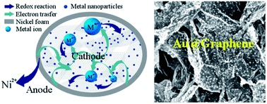
Fig. 1 schematically shows the mechanism of deposition of MNPs via SEED. As GHG@NF is immersed into metal ion solutions, the system becomes a galvanic cell: GHG acts as the anode where reduction of metal ions in solution takes place, while the NF serves as a cathode which is oxidized. Owing to the excellent conductivity of both NF and GHG, electrons can transfer easily from NF to metal ions in the solution, via GHG network.29 Since galvanic cell reaction is much faster than corresponding direct redox reactions, the deposition of MNP is strongly accelerated. And any metal with a redox potential higher than Ni can deposit on GHG, forming MNP/GHG composites. We first used this method to prepare gold nanoparticle/GHG (AuNP@GHG) composites. Fig. 2a and b shows the SEM images of GHG@NF. A typical 3D network composed of 2D sheets inside the pores of NF can be found in the images, and the pore sizes of the graphene network are in the range of several micrometers to tens of micrometers. After immersing the GHG@NF into an aqueous solution of HAuCl4 (4 mM) for 5 s, a number of AuNPs formed on graphene sheets, with sizes ranging from several nanometers to tens of nanometers (Fig. 2c), revealing a very fast reaction rate. When the exposing time was increased to 10 s, a dense and homogeneous assembly of AuNPs with an average diameter of about 58 nm formed on the surface of GHG, as shown in Fig. 2d. The EDX result confirms the existence of Au element and the absence of Cl element, demonstrating the successful reduction of AuCl4 (Fig. 2h). Thanks to the excellent conductivity of the GHG,37 electrons can easily transfer from NF to any rGO sheet in GHG, leading to a homogeneous distribution of AuNPs on GHG. On the other hand, small particles grow more quickly than the large ones due to their higher surface to volume ratios, resulting in even size distribution of AuNPs.32 If the exposing time was further extended to 20 s and 30 s, the average diameters of AuNPs on the surface of GHG increased to about 70 nm and 80 nm, respectively (Fig. 2e and f). TEM image (Fig. 2g) shows that the AuNPs in the composite are polycrystal with irregular shape. It should be noted that AuNPs at different depth in GHG@NF show different size (Fig. S1). The reason is that when GHG@NF is immersed into metal ion solution, there exists a metal ion concentration gradient inside it, due to slow diffusion of metal ions. AuNPs grow faster when the concentration of metal ion is higher. Therefore, it is observed that both particle size and density of AuNPs on GHG decrease from the surface to the center of NF (Fig. S1). If uniform AuNPs are desired the thickness of GHG@NF should be reduced.
image file: c3ra47950a-f1.tif
Fig. 1 Schematic illustration of deposition of MNPs on GHG@NF via SEED.

image file: c3ra47950a-f2.tif
Fig. 2 Electron microscopic images and EDX spectrum of GHG@NF or AuNP@GHG. (a) SEM image of GHG@NF; (b) magnified image of (a); (c)–(f) AuNP@GHG composites with deposition time of (c) 5 s, (d) 10 s, (e) 20 s and (f) 30 s. (g) The typical TEM images of AuNP@GHG composite. (h) EDX spectra for the AuNP@GHG composite. Scale bar: (a) 100 μm, (b)–(f) 1 μm, (g) 100 nm, inset 2 nm.

Similarly, after immersing GHG@NF into aqueous solutions of H2PtCl6 (4 mM, PtCl62−/Pt, +0.68 V) and H2PdCl4 (4 mM, PdCl42−/Pd, +0.591 V),30 platinum nanoparticle/GHG (PtNP@GHG) and palladium nanoparticle (PdNP@GHG) composites were obtained by SEED. These MNP@GHG composites were confirmed by EDX analysis (Fig. 3), which clearly show the peaks of Pt and Pd, respectively. The size distribution of the nanoparticles decorated on GHG was homogeneous for all samples, and the average diameters of Pt and Pd nanoparticles were 150 nm and 5 nm, respectively, after 10 second SEED (Fig. 3). Moreover, the density of Pt and Pd nanoparticles showed a significant increase with deposition time, while there was no obvious increase of particle sizes, which was similar with the phenomenon in the deposition of AuNPs (Fig. S2 and S3). PdNP, however, grows faster than PtNP, as shown in Fig. S2 and S3 within a deposition time of 30 s, PdNPs covered almost the entire surface of rGO sheets, while PtNPs on rGO sheets after 30 s were still discrete. Both MNP@GHG composites were also investigated by TEM, as shown in Fig. S2d and S3d. The TEM images reveal that PtNPs in PtNP@GHG composite are built by smaller nanoparticles with an average diameter of about 2.5 nm. PdNPs in TEM images are found to be irregular sphere with an average diameter of about 5 nm.


image file: c3ra47950a-f3.tif
Fig. 3 SEM images and EDX spectra of MNP@GHG composites. (a) PtNP@GHG composites; (b) PdNP@GHG composites. Deposition time: 10 s. Scale bar: 1 μm.

In order to verify that NF substrate plays an important role in SEED, direct reactions between GHG and metal ions solution were carried out and compared with SEED. Firstly, the deposition of Cu nanoparticles by direct reduction or SEED was tested. As rGO sheets have a reduction potential of about +0.38 V and Cu has a redox potential of +0.3419 V (Cu2+/Cu), rGO is supposed to not be able to reduced Cu2+. This is confirmed by SEM image of GHG after soaking in Cu2+ solution for 20 s (Fig. 4a), in which no Cu nanoparticle (CuNP) is found. In the case of SEED, however, CuNPs with an average diameter of about 75 nm formed after immersing GHG@NF in the same Cu2+ solution for 20 s (Fig. 4b). This is because that in SEED the reducing agent is Ni substrate, whose redox potential is much lower than that of Cu2+/Cu. To further confirm the role of Ni substrate, we tried to use SEED method to deposit metals with redox potential lower than that of Ni2+/Ni. Three ions were chosen, namely Co2+ (−0.277 V), Fe2+ (−0.44 V) and Zn2+ (−0.7626 V).30 After GHG@NF composite was soaked in Co(NO3)2, FeSO4 or Zn(CH3COO)2 solution for 60 s, no metal particle was observed on GHG (Fig. S4). These results demonstrated the deposited metals should have redox potential higher than that of Ni. Furthermore, we also found that the Ni substrates can influence the morphology and distribution of MNPs. For example, although AuNPs can grow on pure GHG without the assistance of Ni substrate (Fig. 4c), the coverage of AuNP on GHG is lower than that of the AuNP@GHG composite prepared by SEED, due to relatively slow deposition rate. Besides, the PdNPs obtained by direct reduction are much larger (∼70 nm, Fig. 4d) than those grown via SEED, and the particle density is obviously lower (Fig. S3b†). The distinctions of morphology may result from the different reaction rate of SEED and direct reduction. Generally speaking, fast reaction rate usually leads to small particles, because it allows the formation of more nuclei.38,39 When GHG is supported by NF, the deposition rate of MNPs is strongly accelerated by the galvanic cell reaction. As a result, the density of MNPs on GHG@NF is much higher than that on pure GHG, and the particle size is also smaller.


image file: c3ra47950a-f4.tif
Fig. 4 (a), (c) and (d) SEM images of the GHG samples after direct reaction with CuCl2, HAuCl4 and H2PdCl4 solution for 20 s, respectively. (b) SEM image of the CuNP@GHG composites prepared by SEED in CuCl2 solution for 20 s. Scale bar: 1 μm.

Both graphene and MNP possess excellent electrocatalytic activities and are widely used to modify electrode for biosensors and fuel batteries.40,41 Thus we also investigated the electrocatalytic activities of the MNP@GHG composites. The electrocatalytic property of AuNP@GHG composite was examined by taking uric acid (UA) as the probe.42,43 UA is the major nitrogenous compound in urine and the primary end product of purine metabolism, whose abnormal levels in the body are symptom of several diseases, such as gout, hyperuricemia, and Lesch–Nyhan disease.44 Therefore, it is of significantly importance to develop UA sensors with high sensitivity. Fig. 5a shows cyclic voltammetry (CV) curves of 50 μM UA in 0.1 M PBS (pH = 7.4) on bare GCE, GHG modified GCE and AuNP@GHG composite modified GCE, respectively. CV curves at all the three electrodes show an anodic wave at 0.25–0.5 V vs. SCE, corresponding to the oxidation of UA.45 The cathodic wave on the three electrodes were all negligible, indicating that the electrochemical oxidation of UA on these electrodes was irreversible. UA exhibited only a small oxidation peak current (17.0 μA cm−2) on bare GCE around 0.43 V vs. SCE. Modifying the GCE with GHG or AuNP@GHG composite brought obvious negative shift of the oxidation peak potential to 0.26 V. The peak currents in the CV of UA was increased to 53.8 μA cm−2 on GHG modified GCE, indicating that electrochemical oxidation of UA on the surface of electrode was catalyzed by GHG. On AuNP@GHG modified GCE, the peak current was further increased to 377.7 μA cm−2, much higher than that on GHG modified GCE. The significant enhancement of the current response is attributed to a synergy effect of the electrocatalytic activity of AuNPs, the large surface area and good conductivity of GHG.46 AuNPs have excellent electrocatalytic activity towards oxidation of UA, and when they are supported on GHG, the electron can easily collected by external circuit, because of the high conductivity of GHG. It should be noted that the charging/discharging current of electric double layer in the above two modified GCEs is much larger than that of bare GCE, revealing that 3D structure of GHG or AuNP@GHG is preserved on the GCE, and accessible to the electrolyte. The 3D structure provides large electrode surface area and enable one to load more MNPs on it, thus can further enhance the current response of analyte. Fig. 5b shows the effect of scan rate on CV responses of 50 μM UA in 0.1 M PBS on AuNP@GHG modified GCE. The oxidation peak current density increased linearly with square root of the scan rate in the range of 25 to 250 mV s−1, indicating that the electrode process is controlled by diffusion.47,48


image file: c3ra47950a-f5.tif
Fig. 5 (a) Cyclic voltammograms of 50 μM UA on bare GCE, GHG modified GCE and AuNP@GHG modified GCE in 0.1 M PBS solution (pH = 7.4) at a scan rate of 100 mV s−1. (b) Cyclic voltammograms of 50 μM UA on AuNP@GHG modified GCE in 0.1 M PBS solution (pH = 7.4) at scan rates of 25, 50, 100, 150, 200 and 250 mV s−1 (from a to f). Inset: plot of anodic peak current density vs. square root of the potential scan rate.

To test whether the AuNP@GHG modified electrode can be used to detect UA quantitatively, DPV method was employed, in order to estimate the influence of background current.49 Fig. 6a and b show the DPV curves of various concentrations of UA on AuNP@GHG composite modified GCE and the corresponding calibration curve. The anodic peak current increased linearly with UA concentration ranging from 2 to 40 μM with a correlation coefficient of 0.999 (Fig. 6b), and at higher UA concentration the current reached saturation. The detection limit of the electrode for UA was identified to be 0.48 μM (S/N = 3). It is worthwhile noting that the sensitivity of AuNP@GHG modified GCE towards UA is 10.07 μA μM−1 cm−2, higher than that on many other nanomaterial-modified electrodes, such as graphene/Pt modified GCE (2.10 μA μM−1 cm−2),50 poly(diallyl dimethylammonium chloride)@helical carbon nanotubes modified GCE (0.16 μA μM−1 cm−2),51 and LaPO4 nanowires modified carbon paste electrode (0.14 μA μM−1 cm−2).52 The reproducibility of the electrode was examined in 30 μM UA solutions using DPV measurement (Fig. S5). Within a period of one week, seven AuNP@GHG modified GCEs were made under identical conditions and measured. The results show a relative standard deviation (RSD) of 2.76%, indicating the excellent reproducibility of the AuNP@GHG modified electrode. These results demonstrate that AuNP@GHG composite prepared by SEED can be used to fabricate UA amperometric sensors.


image file: c3ra47950a-f6.tif
Fig. 6 (a) DPV responses of different concentrations of UA on AuNPs@GHG modified GCE in 0.1 M PBS (pH = 7.40). (b) The relation between the DPV currents and the concentrations of UA. The blue line shows the linear relationship between DPV current and the concentrations of UA in the range from 2 to 40 μM.

Conclusions

In summary, we have developed a green and facile strategy to prepare MNP@GHG composites using SEED method. By inducing nickel foam as the substrate of GHG, a galvanic cell composed of Ni and rGO in metal salt electrolyte was established, which significantly promotes the deposition of MNPs on GHG. MNPs with redox potentials higher than substrate (Ni), including Au, Pt, Pd and Cu nanoparticles, were deposited successfully onto GHG. The 3D porous structure of GHG facilitates the permeation of metal ion solutions, and the high conductivity of GHG ensures the easy transfer of electrons. The produced AuNP@GHG composite showed good electrocatalytic activity, towards the oxidation of UA, owing to the large surface area and excellent conductivity of GHG, and the prominent electrocatalytic activity of AuNPs. The amperometric sensor fabricated with AuNP@GHG composite modified electrode shows good sensitivity towards UA. Considering the universality and simplicity of the SEED method developed here, we believe that it is valuable in producing metal/graphene 3D composites which have practical applications in areas of energy, environment and bio-medicine.

Acknowledgements

The authors thank the National Natural Science Foundation of China (21104041) for financial support.

Notes and references

  1. M. D. Stoller, S. Park, Y. Zhu, J. An and R. S. Ruoff, Nano Lett., 2008, 8, 3498–3502 CrossRef CAS PubMed.
  2. K. S. Novoselov, A. K. Geim, S. V. Morozov, D. Jiang, Y. Zhang, S. V. Dubonos, I. V. Grigorieva and A. A. Firsov, Science, 2004, 306, 666–669 CrossRef CAS PubMed.
  3. A. A. Balandin, S. Ghosh, W. Bao, I. Calizo, D. Teweldebrhan, F. Miao and C. N. Lau, Nano Lett., 2008, 8, 902–907 CrossRef CAS PubMed.
  4. C. Lee, X. Wei, J. W. Kysar and J. Hone, Science, 2008, 321, 385–388 CrossRef CAS PubMed.
  5. S. Park and R. S. Ruoff, Nat. Nanotechnol., 2009, 4, 217–224 CrossRef CAS PubMed.
  6. W. J. Yuan and G. Q. Shi, J. Mater. Chem. A, 2013, 1, 10078–10091 CAS.
  7. Y. X. Liu, X. C. Dong and P. Chen, Chem. Soc. Rev., 2012, 41, 2283–2307 RSC.
  8. F. Bonaccorso, Z. Sun, T. Hasan and A. C. Ferrari, Nat. Photonics, 2010, 4, 611–622 CrossRef CAS.
  9. C. R. Dean, A. F. Young, I. Meric, C. Lee, L. Wang, S. Sorgenfrei, K. Watanabe, T. Taniguchi, P. Kim, K. L. Shepard and J. Hone, Nat. Nanotechnol., 2010, 5, 722–726 CrossRef CAS PubMed.
  10. A. S. Mayorov, R. V. Gorbachev, S. V. Morozov, L. Britnell, R. Jalil, L. A. Ponomarenko, P. Blake, K. S. Novoselov, K. Watanabe, T. Taniguchi and A. K. Geim, Nano Lett., 2011, 11, 2396–2399 CrossRef CAS PubMed.
  11. Y. Q. Chen, K. W. Chen, H. Bai and L. Li, J. Mater. Chem., 2012, 22, 17800–17804 RSC.
  12. K. W. Chen, L. B. Chen, Y. Q. Chen, H. Bai and L. Li, J. Mater. Chem., 2012, 22, 20968–20976 RSC.
  13. J. Chen, C. Li and G. Q. Shi, J. Phys. Chem. Lett., 2013, 4, 1244–1253 CrossRef CAS.
  14. Y. Q. Chen, L. B. Chen, H. Bai and L. Li, J. Mater. Chem. A, 2013, 1, 1992–2001 CAS.
  15. H. Wang, X. Z. Yuan, Y. Wu, H. J. Huang, X. Peng, G. M. Zeng, H. Zhong, J. Liang and M. M. Ren, Adv. Colloid Interface Sci., 2013, 195–196, 19–40 CrossRef CAS PubMed.
  16. H. J. Qiu, X. C. Dong, B. Sana, T. Peng, D. Paramelle, P. Chen and S. Lim, ACS Appl. Mater. Interfaces, 2013, 5, 782–787 CAS.
  17. Y. F. Li, H. Q. Yu, H. Li, C. G. An, K. Zhang, K. M. Liew and X. F. Liu, J. Phys. Chem. C, 2011, 115, 6229–6234 CAS.
  18. H. J. Guo and S. H. Sun, J. Am. Chem. Soc., 2012, 134, 2492–2495 CrossRef PubMed.
  19. J. B. Liu, S. H. Fu, B. Yuan, Y. L. Li and Z. X. Deng, J. Am. Chem. Soc., 2010, 132, 7279–7281 CrossRef CAS PubMed.
  20. R. Muszynski, B. Seger and P. V. Kamat, J. Phys. Chem. C, 2008, 112, 5263–5266 CAS.
  21. K. Jasuja and V. Berry, ACS Nano, 2009, 3, 2358–2366 CrossRef CAS PubMed.
  22. Y. K. Kim, H. K. Na, Y. W. Lee, H. Jang, S. W. Han and D. H. Min, Chem. Commun., 2010, 46, 3185–3187 RSC.
  23. S. J. Xu, L. Yong and P. Y. Wu, ACS Appl. Mater. Interfaces, 2013, 5, 654–662 CAS.
  24. C. Zhong, J. Z. Wang, X. W. Gao, D. Wexler and H. K. Liu, J. Mater. Chem. A, 2013, 1, 10798–10804 CAS.
  25. K. Jasuja, J. Linn, S. Melton and V. Berry, J. Phys. Chem. Lett., 2010, 1, 1853–1860 CrossRef CAS.
  26. D. Marquardt, C. Vollmer, R. Thomann, P. Steurer, R. Mülhaupt, E. Redel and C. Janiak, Carbon, 2011, 49, 1326–1332 CrossRef CAS PubMed.
  27. H. M. A. Hassan, V. Abdelsayed, A. E. R. S. Khder, K. M. AbouZeid, J. Terner, M. S. El-Shall, S. I. Al-Resayes and A. A. El-Azhary, J. Mater. Chem., 2009, 19, 3832–3837 RSC.
  28. K. Vinodgopal, B. Neppolian, N. Salleh, I. V. Lightcap, F. Grieser, M. Ashokkumar, T. T. Ding and P. V. Kamat, Colloids Surf., A, 2012, 409, 81–87 CrossRef CAS PubMed.
  29. I. V. Lightcap, T. H. Kosel and P. V. Kamat, Nano Lett., 2010, 10, 577–583 CrossRef CAS PubMed.
  30. W. M. Haynes and D. R. Lide, Handbook of chemistry and physics, CRC Press, Boca Raton, USA, 90th edn, 2010 Search PubMed.
  31. B. S. Kong, J. Geng and H. T. Jung, Chem. Commun., 2009, 2174–2176 RSC.
  32. L. T. Qu and L. M. Dai, J. Am. Chem. Soc., 2005, 127, 10806–10807 CrossRef CAS PubMed.
  33. X. W. Liu, J. J. Mao, P. D. Liu and X. W. Wei, Carbon, 2011, 49, 477–483 CrossRef CAS PubMed.
  34. J. Chen, K. X. Sheng, P. H. Luo, C. Li and G. Q. Shi, Adv. Mater., 2012, 24, 4569–4573 CrossRef CAS PubMed.
  35. W. S. Hummers and R. E. Offeman, J. Am. Chem. Soc., 1958, 80, 1339 CrossRef CAS.
  36. Y. X. Xu, L. Zhao, H. Bai, W. J. Hong, C. Li and G. Q. Shi, J. Am. Chem. Soc., 2009, 131, 13490–13497 CrossRef CAS PubMed.
  37. K. X. Sheng, Y. X. Xu, C. Li and G. Q. Shi, New Carbon Mater., 2011, 26, 9–15 CrossRef CAS.
  38. A. B. R. Mayer and J. E. Mark, Eur. Polym. J., 1998, 34, 103–108 CrossRef CAS.
  39. M. Chen, J. P. Liu and S. H. Sun, J. Am. Chem. Soc., 2004, 126, 8394–8395 CrossRef CAS PubMed.
  40. D. Chen, H. B. Feng and J. H. Li, Chem. Rev., 2012, 112, 6027–6053 CrossRef CAS PubMed.
  41. B. E. Hayden, Acc. Chem. Res., 2013, 46, 1858–1866 CrossRef CAS PubMed.
  42. W. J. Hong, H. Bai, Y. X. Xu, Z. Y. Yao, Z. Z. Gu and G. Q. Shi, J. Phys. Chem. C, 2010, 114, 1822–1826 CAS.
  43. Y. Xue, H. Zhao, Z. J. Wu, X. J. Li, Y. J. He and Z. B. Yuan, Biosens. Bioelectron., 2011, 29, 102–108 CrossRef CAS PubMed.
  44. V. V. S. E. Dutt and H. A. Mottola, Anal. Chem., 1974, 46, 1777–1781 CrossRef CAS.
  45. D. Sun, Y. Zhang, F. R. Wang, K. B. Wu, J. W. Chen and Y. k. Zhou, Sens. Actuators, B, 2009, 141, 641–645 CrossRef CAS PubMed.
  46. W. Qin and X. Li, J. Phys. Chem. C, 2010, 114, 19009–19015 CAS.
  47. P. Kalimuthu, J. Tkac, U. Kappler, J. J. Davis and P. V. Bernhardt, Anal. Chem., 2010, 82, 7374–7379 CrossRef CAS PubMed.
  48. X. X. Wang, N. J. Yang, Q. J. Wan and X. Wang, Sens. Actuators, B, 2007, 128, 83–90 CrossRef CAS PubMed.
  49. M. Hadi and A. Rouhollahi, Anal. Chim. Acta, 2012, 721, 55–60 CrossRef CAS PubMed.
  50. C. L. Sun, H. H. Lee, J. M. Yang and C. C. Wu, Biosens. Bioelectron., 2011, 26, 3450–3455 CrossRef CAS PubMed.
  51. B. Y. Zhang, D. K. Huang, X. B. Xu, G. Alemu, Y. B. Zhang, F. Zhan, Y. Shen and M. K. Wang, Electrochim. Acta, 2013, 91, 261–266 CrossRef CAS PubMed.
  52. Y. Z. Zhou, H. Y. Zhang, H. D. Xie, B. Chen, L. Zhang, X. H. Zheng and P. Jia, Electrochim. Acta, 2012, 75, 360–365 CrossRef CAS PubMed.

Footnote

Electronic supplementary information (ESI) available: Additional SEM images of AuNP@GHG, PtNP@GHG and PdNP@GHG composites, stability, repeatability and selectivity of the AuNP@GHG modified electrode. See DOI: 10.1039/c3ra47950a

This journal is © The Royal Society of Chemistry 2014
Click here to see how this site uses Cookies. View our privacy policy here.