 Open Access Article
Creative Commons Attribution 3.0 Unported Licence
Carbon aerogels from bacterial nanocellulose as anodes for lithium ion batteries
Liping Wanga,
Christina Schützbc,
German Salazar-Alvarez*bc and
Maria-Magdalena Titirici*d
aMax Planck Institute of Colloids and Interfaces, Am Mühlenberg 1, 14476 Potsdam, Germany
bDepartment of Materials and Environmental Chemistry, Arrhenius Laboratory, Stockholm University, Stockholm, SE-106 91, Sweden. E-mail: german@mmk.su.se
cWallenberg Wood Science Center, KTH, Teknikringen 56, Stockholm, SE-100 44, Sweden
dSchool of Materials Science and Engineering, Queen Mary University of London, Mile End Road, London, E1 4NS, UK. E-mail: m.m.titirici@qmul.ac.uk
First published on 2nd April 2014
Abstract
Carbon aerogels with large open pores and high surface area are fabricated via pyrolysis of a readily available natural resource, e.g., bacterial nanocellulose (BNC) aerogels. Freeze-drying of the BNC hydrogels is used to preserve the 3D open network structure upon calcination whereas using Fe(III) improves the yield and H/C ratio. These carbon aerogels are explored as anodes in lithium ion batteries where it is shown that they deliver superior capacity retention and rate performance compared to other carbon-based materials.
1 Introduction
The search for alternative energy sources to fossil fuels has increased in the recent years due to growing environmental concerns and an increasing oil price. Conventional non-fossil energy sources (such as wind, solar, and hydroelectric power) deliver energy continuously whether it is used or not. As such, it is advantageous to develop energy storage media which can also be light and easy to transport. In this regard, lithium ion batteries (LIBs) are one of the best alternatives due to their relatively light weight, high energy and power density.1–4Carbon is the most commonly used anode material in commercial LIBs because of its low price, low lithium ion intercalation potential and good cyclic stability.5 Nevertheless, since carbon anodes may suffer of poor rate performance due to a slow lithium diffusivity,5 intense efforts have been devoted to finding alternative anodes with different compositions, mostly oxides.6 However, the poor rate performance can be greatly improved by reducing the travel distance of the lithium ions within the carbon matrix. Mesoporous carbons have shown an improved rate performance and enhanced capacity,7,8 particularly in combination with carbon nanotubes.9 Carbon materials derived from renewable natural, abundant nanomaterials, e.g., cellulose, chitin, collagen, and silk, may play an important role as they are available at a very low cost and readily available in developing countries.10 Moreover, these renewable carbon materials can be produced using much simpler methodologies, i.e. pyrolysis11,12 and hydrothermal carbonization.13,14
In this respect, nanocellulose15,16 is emerging as a cheap, abundant, biodegradable, and sustainable polymeric material with useful functional properties such as tailored hydro/oleophilicity, optical transparency, and remarkable mechanical performance both as films and aerogels.17–21 Particularly, bacterial nanocellulose (BNC),15,16 which is readily obtained from cell cultures of G. xylinum and widely available as a dessert in South-East Asia,22 has been suggested as a convenient scaffold for the preparation of functional materials with magnetic,23 optical,24 and mechanical properties due to their open network structure and low apparent density.16,22 While nanocellulose fibres have recently been used as substrates for the deposition of active battery components25,26 and also as binder and electrode separators,27 very little work has been focusing on the fabrication of electrically conducting nanocellulose-based systems where the open network structure is exploited.28–30
In this work, we study the behaviour of a carbon aerogel network obtained through the pyrolysis of BNC aerogels as anode material in LIBs. The pyrolyzed fibres show a disordered structure with an enhanced surface area, resulting in anode materials with a good rate performance and capacity retention. Our results suggest that ordered graphitic layers are not a requirement for achieving high capacity, thus avoiding the use of high temperatures during the fabrication process.
2 Results and discussion
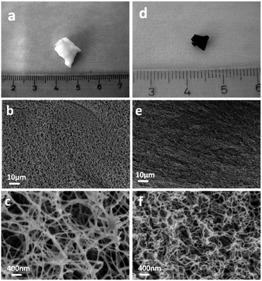
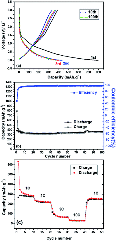
Fig. 1 shows freeze-dried BNC (FD-BNC, Fig. 1a–c) aerogel with a highly porous network and the preserved nanofibrillar network after pyrolysis at 900 °C (FD-BNC-900, Fig. 1d–f). The fiber thickness decreased from ca. 20–70 nm to about 20 nm. The original monolith reduced considerably its volume after the pyrolysis mostly due to the loss of water and release of CO and CO2 occurred around 300 °C.31 Normally a direct calcination of a gel body can lead a large shrinkage and collapse the network structure by capillary forces acting on the pore walls.32 However, although different drying techniques have been explored to maintained the porosity of nanocellulose-based materials,33 the freeze-drying method can circumvent the drawbacks of direct thermal treatment and preserve the open porous networks.19The obtained BNC-derived carbon (FD-BNC-900) was subsequently used as the anode in LIBs. The charge–discharge curves at a current density of 75 mA g−1, namely 0.2 C (1 C = 372 mA g−1), are shown in Fig. 2a. The initial discharge and charge capacity are 797 mA h g−1 and 386 mA h g−1, respectively. The cycling performance and coulombic efficiency of the BNC-derived material were also studied as shown in Fig. 2b. The initial charge capacity of 386 mA h g−1 decreased to 359 mA h g−1 after 100 cycles. After an initial adjustment of the coulombic efficiency, probably due to stabilisation of the solid electrolyte interphase and the disordered structure.8,34 The capacity increases slightly during the cycling, likely due to the activation of the disordered structure.34 The capacity fade rate can be calculated to be 0.07% per cycle, which means that the capacity retention ability is very good. The capacity of the carbon aerogel as electrode is considerably better than that obtained for carbonized films produced also from BNC, which was reported to be just about 100 mA h g−1.35 The cellulose-derived carbon shows also a superior rate performance (Fig. 2c). The cell was directly discharged–charged at various current densities from 0.375 A g−1 (1 C) to 3.75 A g−1 (10 C) each for 10 cycles. The reversible capacities are 288, 228, 94, and 34 mA h g−1 at 0.375 A g−1 (1 C), 0.75 A g−1 (2 C), 1.875 A g−1 (5 C), and 3.75 A g−1 (10 C, namely 6 minutes to full charge), respectively. When the rate is tuned back to 0.375 A g−1 after cycling at different current rates, the capacity can be recovered to 250 mA h g−1, which evidences the stable cycling performance of the freeze-dried carbon aerogel.
Compared with mesoporous carbons7,8 our sample exhibits a lower capacity but a much better capacity retention behavior at the same current rate of 0.2 C. The superior electrochemical performance of the carbon aerogel is attributed to its high surface area, open 3D network and the crosslinking between the carbon nanofibres. The high surface area and open pore structure offer a large electrode/electrolyte contact area, favorable for charge-transfer reaction, whereas the crosslinking of the nanofibres ensures a continuous electron transport. Moreover, the thin fibres with diameters of about 20 nm guarantee a very short diffusion distance for the lithium ion. All of these parameters are indispensable for the stable capacity and high rate performance.
In order to investigate the porosity of the FD-BNC and FD-BNC-900, N2 sorption isotherms have been recorded (Fig. 3). The FD-BNC has a total pore volume of 0.23 cm3 g−1 and a BET surface area of 109 m2 g−1, characteristic of materials without any apparent pores. After pyrolysis at 900 °C in N2, the shape of the adsorption isotherm is maintained suggesting the maintenance of the structure and the presence of micropores. The BET surface area and the pore volume of FD-BNC-900 increased to 670 m2 g−1 and 0.83 cm3 g−1, respectively. The enhancement of surface area and pore volume can be ascribed to removal of water from the cellulose structure and the severe contraction of the fibres from about 50 nm to about 20 nm during pyrolysis. Compared with traditional carbon nanofibres with high surface area normally obtained by chemical or physical activation with tedious work, our procedure is much easier and greener.
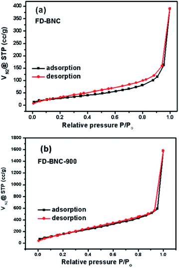 | ||
| Fig. 3 Nitrogen sorption isotherms of (a) freeze-dried bacterial nanocellulose (FD-BNC) aerogels and (b) freeze-dried bacterial nanocellulose pyrolyzed at 900 °C (FD-BNC-900). | ||
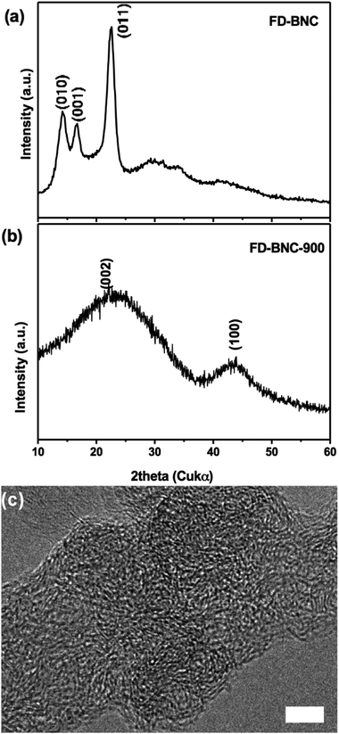
Fig. 4a and b show the XRD profiles of FD-BNC and its carbon residue after pyrolysis. The XRD pattern of FD-BNC aerogels were identified as cellulose Iα (ref. 16) and the characteristic peaks observed at 14.2°, 16.7°, and 22.6° were indexed as the (010), (001), and (011) reflections of the triclinic unit cell, respectively.36 The characteristic sharp peaks indicate that the bacterial cellulose is highly crystalline, in agreement with other reports.30,37 The pyrolysis of BNC resulted in a graphitic-like structure with broad reflection peaks at ca. 24° and 43°, which can be assigned to the (002) and (100) lattice planes of graphite, respectively; in agreement with earlier reports.38 Interestingly, the relatively low pyrolysis temperature resulted in a disordered (and perhaps turbostratic) graphitic structure, as displayed in Fig. 4c. However, it has also been suggested that such relatively disordered structures may result in a decreased capacity,4,39 these misaligned regions may be the origin of the increased surface area and higher rate performance.4
The overall yield, considering the carbon content of nanocellulose after carbonization, is about 25%, which was improved when the BNC was soaked with iron(III) ion as dehydrating agent (FD-BNC-Fe1200). The elemental analysis of the samples is provided in Table 1. The analysis indicates that sample FD-BNC-900 has a final carbon content is 90.96 wt% and a small amount of other elements, where most likely oxygen is still present in the fibres probably as aldehyde groups, carbonates or carboxylates, in agreement with recent results.30 The sample soaked with iron shows a much lower hydrogen content, reflecting a more efficient pyrolysis.
| Sample | C/wt% | H/wt% | Others/wt% | H/C mol ratio |
|---|---|---|---|---|
| FD-BNC | 43.07 | 5.83 | 51.10 | 1.624 |
| FD-BNC-900 | 90.96 | 1.63 | 7.41 | 0.215 |
| FD-BNC-Fe1200 | 60.47 | 0.23 | 39.30 | 0.046 |
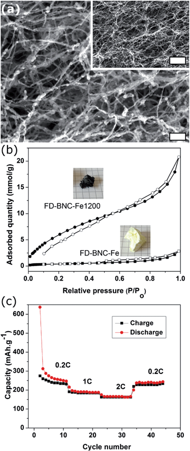
Fig. 5a shows the carbon fibres decorated with 10–30 nm iron-based nanoparticles with a composition close to that of cementite (Fe3C). The fibres retained the nanoscale dimensions and the BET surface area increased from 33 m2 g−1 to 351 m2 g−1 after the pyrolysis process (Fig. 5b), which is expected for the pyrolysed fibres decorated with ca. 40 wt% nanoparticles. In comparison to the FD-BNC-900, the FD-BNC-Fe1200 has a slower performance but it has a remarkable stability. The rate performance of the iron doped carbon aerogel is stable and shows a recovery to 220 mA h g−1 after 45 cycles at different current rates. Fig. 6 shows the Raman spectra for both FD-BNC-900 and FD-BNC-Fe1200. Albeit broad, both spectra display the D and G bands, characteristic for 6-membered aromatic rings,40 at ca. 1340 and 1580 cm−1, respectively. The presence of the bands and their relative ratio, ID/IG, indicates a graphitic correlation length of ca. 1 nm,40 in agreement with the HRTEM images. In the case of FD-BNC-Fe1200, the bands are sharper and also the 2D overtone band (at ca. 2680 cm−1) is clearly visible, indicating a somewhat higher degree of structural order.
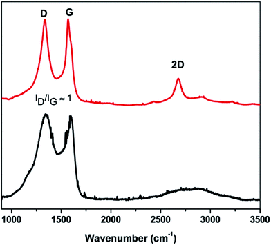 | ||
| Fig. 6 Raman spectra of (bottom trace) FD-BNC-900 and (top trace) FD-BNC-Fe1200. The different bands are labelled and the ID/IG ratio is indicated. | ||
A drawback observed in the electrochemical performance of the tested materials is the large irreversible capacity. This can be due to three different processes: the decomposition of electrolyte, formation of solid electrolyte interphase (SEI), as well as reaction of lithium with the hydrogen present in the sample (see Table 1). The common carbonate-based electrolyte solution (e.g. EC-DEC, EC-DMC) can easily have a reduction reaction below 1.0 V (versus Li+) and an oxidation reaction above the voltage of 4.5 V (versus Li+) to form an electronically insulating but lithium ion conductive film on the electrode active material.2 The H/C molar ratio of the pyrolyzed aerogel is relatively low, i.e., H/C = 0.215, but seems to influence the electrochemical performance, being the effect particularly noticeable in the first cycle, where the capacity is well beyond the theoretical limit of graphite. The capacity obtained in this first cycle is indeed matching that expected for one lithium atom being bound by one hydrogen atom, i.e., ca. 800 mA h g−1.4 However, the capacity and the shape of charge–discharge curves are quite similar after the first cycle, suggesting that the formation of the SEI stabilizes after the initial cycle. Herein, we have to emphasize that if we expect to build a lithium ion cell, understanding and controlling the phenomena occurring during the initial cycles is always primordial independent of the electrode material with low operation voltage as anode or with high operation voltage as cathode.
3 Conclusions
In this study, the fabrication of a carbon aerogel composed of nanofibres of about 20 nm in diameter was accomplished by pyrolysis of the readily available bacterial nanocellulose (BNC). The 3D open network of the BNC aerogel was preserved from capillary-induced shrinkage and collapse through a freeze-drying method before calcination. The carbon nanofibres showed high surface area and pore volume which favors mass transportation and leads to a very good electrochemical performance in terms of both capacity retention as well as rate performance. The present work can possibly broaden the possibility of an economical and eco-friendly use of cellulose to produce 3D open networks of carbon nanofibres not only for energy storage applications but also for other applications such as adsorption, (electro)catalysis, chromatography or even medical applications. We can already foresee that such an interesting and disordered carbon morphology will have a good performance in Na-ion batteries systems which is a new emerging technology giving the limited availability of lithium and the abundance and low cost of sodium around the globe.4 Experimental
4.1 Pyrolysis of BNC
Coconut gel cubes (ca. 1 × 1 × 1 cm3, Chaokoh, Thailand) were washed three times with 2 dm3 of deionized water and stirred in 2 dm3 of a 0.1 M sodium hydroxide solution for 48 hours to remove any adsorbed components. The materials were further washed with deionized water until the pH stabilized at around 7. The BNC cubes were frozen in liquid nitrogen (−196 °C) and freeze-dried in a vacuum chamber at a temperature of −80 °C. The freeze-dried BNC aerogels (labeled as FD-BNC) were then pyrolyzed under N2 at 900 °C for 2 hours using a heating rate of 30 °C min−1 to obtain monolithic black carbon (denoted as FD-BNC-900). Alternatively, the freeze-dried BNC cubes (FD-BNC) were soaked with a 0.005 M FeCl3 solution and subsequently freeze-dried (FD-BNC-Fe). The pyrolysis was carried out under argon atmosphere at 1200 °C for 2 hours and a heating rate of 1 °C min−1 (denoted as FD-BNC-Fe1200).4.2 Characterisation
The size and morphology of all the samples were visualized using electron microscopy facilities (Gemini Leo-1550 SEM or Jeol JEM-7401 SEM and Omega 912 TEM). Nitrogen adsorption/desorption isotherms were measured at 77 K using a Quantachrome Quadrasorb Adsorption Instrument or a Micromeritics ASAP 2020 where the BET method was used for surface area determination. Elemental composition was determined using a Vario E1 elemental analyzer. XRD patterns were recorded with a Bruker-D8 apparatus with Cu radiation. Each pattern was recorded with a step size of 0.03°. TGA was performed on a Perkin-Elmer Thermogravimetric Analyzer TGA7. The Raman spectra were recorded with a Horiba LabRAM HR 800 spectroscope using a 532 nm laser.4.3 Electrochemical test
The electrode was prepared by mixing powder (80 wt%), carbon black (10 wt%), and polyvinylidene fluoride (PVDF, 10 wt%) in N-methylpyrrolidone (NMP) to form a homogenous slurry. The slurry was then spread onto a copper foil and dried at 100 °C for overnight in a vacuum oven. 1 M LiPF6 in a mixture of ethylene carbonate (EC), dimethyl carbonate (DMC) (1![[thin space (1/6-em)]](https://www.rsc.org/images/entities/char_2009.gif) :
:![[thin space (1/6-em)]](https://www.rsc.org/images/entities/char_2009.gif) 1 by volume) was used as the electrolyte. The assembly of the test cells was carried out in an argon-filled glove box. The batteries were charged and discharged at different rates from 0.2 C to 10 C between 0.0 and 3.0 V on a LAND CT2001A cell test apparatus (1 C corresponding to 372 mA g−1 of current rate).
1 by volume) was used as the electrolyte. The assembly of the test cells was carried out in an argon-filled glove box. The batteries were charged and discharged at different rates from 0.2 C to 10 C between 0.0 and 3.0 V on a LAND CT2001A cell test apparatus (1 C corresponding to 372 mA g−1 of current rate).
Acknowledgements
We would like to thank Rui Wang (Institute of Physics, Chinese Academy of Sciences) for help of electrochemical measurements and Markus Antonietti (Max Planck Institute of Colloids and Interfaces) for providing LW with a post-doctoral fellowship. CS and GSA thank the Wallenberg Wood Science Center for financial support and the Knut and Alice Wallenberg Foundation for the electron microscopy facilities, and Eva Björkman (Stockholm University) for fruitful discussions.References
- J. M. Tarascon and M. Armand, Nature, 2001, 414, 359–367 CrossRef CAS PubMed.
- J. B. Goodenough and Y. Kim, Chem. Mater., 2010, 22, 587–603 CrossRef CAS.
- K. Sawai, Y. Iwakoshi and T. Ohzuku, Solid State Ionics, 1994, 69, 273–283 CrossRef CAS.
- J. R. Dahn, T. Zheng, Y. Liu and J. S. Xue, Science, 1995, 270, 590–593 CAS.
- M. Wakihara, Mater. Sci. Eng., R, 2001, 33, 109–134 CrossRef.
- M. V. Reddy, G. V. Subba Rao and B. V. R. Chowdari, Chem. Rev., 2013, 113, 5364–5457 CrossRef CAS PubMed.
- H. Zhou, S. Zhu, M. Hibino, I. Honma and M. Ichihara, Adv. Mater., 2003, 15, 2107–2111 CrossRef CAS.
- Y.-S. Hu, P. Adelhelm, B. M. Smarsly, S. Hore, M. Antonietti and J. Maier, Adv. Funct. Mater., 2007, 17, 1873–1878 CrossRef CAS.
- B. Guo, X. Wang, P. F. Fulvio, M. Chi, S. M. Mahurin, X.-G. Sun and S. Dai, Adv. Mater., 2011, 23, 4661–4666 CrossRef CAS PubMed.
- B. Wicklein and G. Salazar-Alvarez, J. Mater. Chem. A, 2013, 1, 5469 CAS.
- F. Zhang, K.-X. Wang, G.-D. Li and J.-S. Chen, Electrochem. Commun., 2009, 11, 130–133 CrossRef CAS PubMed.
- A. Caballero, L. Hernán and J. Morales, ChemSusChem, 2011, 4, 658–663 CrossRef CAS PubMed.
- B. Hu, K. Wang, L. Wu, S.-H. Yu, M. Antonietti and M.-M. Titirici, Adv. Mater., 2010, 22, 813–828 CrossRef CAS PubMed.
- Q. Wang, H. Li, L. Chen and X. Huang, Carbon, 2001, 39, 2211–2214 CrossRef CAS.
- D. Klemm, F. Kramer, S. Moritz, T. Lindström, M. Ankerfors, D. Gray and A. Dorris, Angew. Chem., Int. Ed., 2011, 50, 5438–5466 CrossRef CAS PubMed.
- R. J. Moon, A. Martini, J. Nairn, J. Simonsen and J. Youngblood, Chem. Soc. Rev., 2011, 40, 3941–3994 RSC.
- C. Aulin, J. Netrval, L. Wågberg and T. Lindström, Soft Matter, 2010, 6, 3298 RSC.
- A. Isogai, T. Saito and H. Fukuzumi, Nanoscale, 2011, 3, 71–85 RSC.
- H. Sehaqui, M. Salajkova, Q. Zhou and L. A. Berglund, Soft Matter, 2010, 6, 1824–1832 RSC.
- H. Jin, M. Kettunen, A. Laiho, H. Pynnönen, J. Paltakari, A. Marmur, O. Ikkala and R. H. A. Ras, Langmuir, 2011, 27, 1930–1934 CrossRef CAS PubMed.
- N. Cervin, C. Aulin, P. Larsson and L. Wågberg, Cellulose, 2012, 1–10 Search PubMed.
- M. Iguchi, S. Yamanaka and A. Budhiono, J. Mater. Sci., 2000, 5, 261–270 CrossRef.
- R. T. Olsson, M. A. S. Azizi Samir, G. Salazar-Alvarez, L. Belova, V. Ström, L. A. Berglund, O. Ikkala, J. Nogués and U. W. Gedde, Nat. Nanotechnol., 2010, 5, 584–588 CrossRef CAS PubMed.
- A. N. Nakagaito, M. Nogi and H. Yano, MRS Bull., 2011, 35, 214–218 CrossRef.
- G. Nyström, A. Razaq, M. Strømme, L. Nyholm and A. Mihranyan, Nano Lett., 2009, 9, 3635–3639 CrossRef PubMed.
- L. Hu, N. Liu, M. Eskilsson, G. Zheng, J. McDonough, L. Wågberg and Y. Cui, Nano Energy, 2013, 2, 138–145 CrossRef CAS PubMed.
- S. Leijonmarck, A. Cornell, G. Lindbergh and L. Wågberg, J. Mater. Chem. A, 2013, 1, 4671 CAS.
- H.-W. Liang, Q.-F. Guan, Z. Zhu, L.-T. Song, H.-B. Yao, X. Lei and S.-H. Yu, NPG Asia Mater., 2012, 4, e19 CrossRef.
- B. Wang, X. Li, B. Luo, J. Yang, X. Wang, Q. Song, S. Chen and L. Zhi, Small, 2013, 9, 2399–2404 CrossRef CAS PubMed.
- Z.-Y. Wu, C. Li, H.-W. Liang, J.-F. Chen and S.-H. Yu, Angew. Chem., Int. Ed., 2013, 52, 2925–2929 CrossRef CAS PubMed.
- M. Tang and R. Bacon, Carbon, 1964, 2, 211–220 CrossRef CAS.
- N. Hüsing and U. Schubert, Angew. Chem., Int. Ed., 1998, 37, 22–45 CrossRef.
- A. Svensson, T. Larsson, G. Salazar-Alvarez and L. Wågberg, Carbohydr. Polym., 2012, 92, 775–783 CrossRef PubMed.
- L. Wang, Z. Schnepp and M. M. Titirici, J. Mater. Chem. A, 2013, 1, 5269 CAS.
- H. Take, S. Yamanaka, M. Ishihara and K. Yoshino, Jpn. J. Appl. Phys., 2002, 41, 3137–3139 CrossRef CAS.
- Y. Nishiyama, J. Sugiyama, H. Chanzy and P. Langan, J. Am. Chem. Soc., 2003, 125, 14300–14306 CrossRef CAS PubMed.
- D. Klemm, B. Heublein, H.-P. Fink and A. Bohn, Angew. Chem., Int. Ed., 2005, 44, 3358–3393 CrossRef CAS PubMed.
- S. Kuga, D.-Y. Kim, Y. Nishiyama and R. M. Brown, Mol. Cryst. Liq. Cryst., 2002, 387, 13–19 CrossRef CAS.
- J. L. Tirado, Mater. Sci. Eng., R, 2003, 40, 103–136 CrossRef.
- A. Ferrari and J. Robertson, Phys. Rev. B, 2000, 61, 14095–14107 CrossRef CAS.
| This journal is © The Royal Society of Chemistry 2014 |

