 Open Access Article
Creative Commons Attribution 3.0 Unported Licence
Mesoporous manganese-deficient lithium manganese silicate cathodes for lithium-ion batteries†
Rosalind J.
Gummow
*a and
Yinghe
He
b
aSchool of Engineering and Physical Sciences, James Cook University, Townsville, Queensland, Australia. E-mail: Rosalind.gummow@jcu.edu.au; Fax: +61 747816788; Tel: +61 747816223
bSchool of Engineering and Physical Sciences, James Cook University, Townsville, Queensland, Australia. E-mail: Yinghe.he@jcu.edu.au; Fax: +61 747816788; Tel: +61 747814312
First published on 14th February 2014
Abstract
Mesoporous electrode materials are favourable for lithium-ion batteries as they have high surface area and provide short lithium-ion diffusion distances from the pore space into the thin pore walls. The porous morphology is also an advantage for buffering the large volume changes that can accompany lithium insertion and extraction. For this reason, this study investigates the synthesis of mesoporous lithium manganese silicate, using mesoporous silica as a template. It is shown that a mesoporous lithium manganese silicate product, retaining the mesoporous symmetry of the SBA-15 silica precursor, can be formed by emulsion synthesis followed by calcination in an inert atmosphere at 700 °C. These calcination conditions retain the decomposed surfactant as a conductive surface layer on the product phase. Undesired, electrochemically inactive MnO impurities were minimized by reducing the Li![[thin space (1/6-em)]](https://www.rsc.org/images/entities/char_2009.gif) :
:![[thin space (1/6-em)]](https://www.rsc.org/images/entities/char_2009.gif) Mn ratio to 2
Mn ratio to 2![[thin space (1/6-em)]](https://www.rsc.org/images/entities/char_2009.gif) :
:![[thin space (1/6-em)]](https://www.rsc.org/images/entities/char_2009.gif) 0.7 in the starting mixture. Rietveld analysis of the X-ray diffraction patterns of the product shows that it is manganese deficient with composition Li2Mn0.87(3)SiO4 with minor impurities of MnO and Li2SiO3. Excellent reversibility is observed for these cathodes in lithium cells with a capacity of 175 mA h g−1 when cycled in constant current–constant voltage mode at a current rate of 20 mA g−1.
0.7 in the starting mixture. Rietveld analysis of the X-ray diffraction patterns of the product shows that it is manganese deficient with composition Li2Mn0.87(3)SiO4 with minor impurities of MnO and Li2SiO3. Excellent reversibility is observed for these cathodes in lithium cells with a capacity of 175 mA h g−1 when cycled in constant current–constant voltage mode at a current rate of 20 mA g−1.
Rechargeable lithium-ion batteries are commonly used today to power portable, electronic devices. Lithium-ion batteries are also being applied as batteries for electric vehicles and for large-scale storage of energy generated from intermittent renewable sources like solar and wind power. Consumer demands for high capacity, long calendar life and low cost are driving the development of new electrode materials to advance this technology.1–4
Mesoporous materials are ordered, porous materials with pores in the range 2–50 nm, typically formed using either soft templates, for example surfactants, or hard templates like mesoporous silica or mesoporous carbon.5,6 Mesoporous materials have been used as lithium-ion battery electrodes for several reasons.7,8 Firstly, the interconnected network of pores allows electrolyte penetration into the bulk of the electrode enabling fast kinetics of lithium diffusion. Secondly, the short lithium diffusion distance from the pore space into the thin pore walls allows rapid kinetics and full utilization of the bulk of the material. Thirdly, the porosity allows accommodation of volumetric changes with cycling and results in stabilization of phases that do not cycle reversibly in bulk form.9,10
Lithium manganese silicate (Li2MnSiO4) is an attractive option as a lithium ion battery cathode with a potential capacity above 300 mA h g−1 if both lithium ions can be extracted reversibly.11 The application of Li2MnSiO4 as a cathode material is, however, complex. The two main drawbacks of Li2MnSiO4 cathodes are, firstly, very low electronic conductivity12,13 resulting in large polarization and low capacity in bulk material,14 and, secondly, structural collapse and amorphization as a result of the large volume changes that occur when large amounts of lithium are extracted on charge.12,13,15,16 The rapid loss of capacity with electrochemical cycling of Li2MnSiO4 cathodes has largely been attributed to this structural collapse.16–19 Both of these problems could be overcome with a mesoporous structure with internal pores to buffer the effect of the volume changes during lithium extraction and insertion, and a conductive surface carbon coating to enhance electronic conductivity.
Herein we report the use of an emulsion synthesis route to prepare a mesoporous cathode material from a mesoporous silica precursor. Emulsion synthesis has been used to prepare a range of lithium battery cathodes.20,21 In this work a water-in-oil emulsion synthesis route is used to prepare a lithium manganese silicate. Droplets of the aqueous phase consist of Li and Mn precursors and a solid mesoporous silica template in suspension. The aqueous phase is dispersed in an organic solvent containing a surfactant. The surfactant is distributed on the surface of the droplets of the aqueous phase (Fig. 1). During calcination in an inert atmosphere or vacuum, reaction occurs between the ordered mesoporous SiO2 and the Li and Mn salts in the aqueous solution to form a lithium manganese silicate. The mesoporous SiO2 acts as a template for the product and the mesoporosity and symmetry of the SiO2 precursor is retained in the product. The mesoporous architecture ensures that the electrolyte penetrates into the bulk of the material, as well as potentially accommodating the volume changes associated with lithium insertion and extraction during cell-cycling. The surfactant molecules on the surface of the droplets decompose to form a conductive surface coating to enhance electronic conductivity.
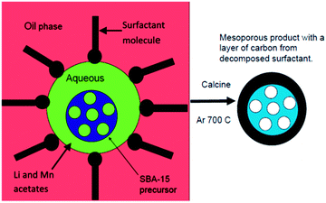 | ||
| Fig. 1 A schematic diagram showing the formation of mesoporous manganese deficient lithium manganese silicate from SBA-15 using emulsion synthesis. | ||
Stoichiometric amounts of lithium acetate dihydrate (LiCH3COO·2H2O) and manganese acetate tetrahydrate (Mn(CH3COO)2·4H2O) were dissolved in distilled water. A stoichiometric amount of either mesoporous silica SBA-15 (SiO2), for the mesoporous sample, or fumed silica, for the bulk control sample, was added and suspended by sonication. This mixture formed the aqueous phase (Fig. 1). The oil phase consisted of cyclohexane as the primary component with 1-butanol and the surfactant Pluronic P123. The ratio of cyclohexane: 1-butanol was typically 8.3![[thin space (1/6-em)]](https://www.rsc.org/images/entities/char_2009.gif) :
:![[thin space (1/6-em)]](https://www.rsc.org/images/entities/char_2009.gif) 1 and 2 g of surfactant was added to 112 ml of mixed organic solvents (1.8 wt%). The solution was mixed vigorously for 1/2 hour to dissolve the surfactant. The aqueous phase was then added to the oil phase to form a milky, water-in-oil emulsion which was magnetically stirred overnight at room temperature. The ratio of aqueous to non-aqueous phases was 1
1 and 2 g of surfactant was added to 112 ml of mixed organic solvents (1.8 wt%). The solution was mixed vigorously for 1/2 hour to dissolve the surfactant. The aqueous phase was then added to the oil phase to form a milky, water-in-oil emulsion which was magnetically stirred overnight at room temperature. The ratio of aqueous to non-aqueous phases was 1![[thin space (1/6-em)]](https://www.rsc.org/images/entities/char_2009.gif) :
:![[thin space (1/6-em)]](https://www.rsc.org/images/entities/char_2009.gif) 3.7 by volume. The precipitate was then allowed to settle out, excess solvent was decanted off and the resulting product was dried on a hot-plate to give a pinky-brown gel. The gel was transferred to a crucible and heated at 500 °C for 10 h in dynamic vacuum to remove organic phases and then at 700 °C in vacuum in a closed tube furnace. The calcination of the precursor materials was performed in vacuum or under Ar, firstly, to prevent oxidation of the product phase and secondly, to retain the carbonaceous decomposition products from the surfactant to enhance the conductivity of the product. The temperature of 700 °C has been shown to be the optimal temperature to reduce impurities and form the Pmn21 polymorph of Li2MnSiO4.14 Emulsion synthesis using a stoichiometric mixture with a Mn
3.7 by volume. The precipitate was then allowed to settle out, excess solvent was decanted off and the resulting product was dried on a hot-plate to give a pinky-brown gel. The gel was transferred to a crucible and heated at 500 °C for 10 h in dynamic vacuum to remove organic phases and then at 700 °C in vacuum in a closed tube furnace. The calcination of the precursor materials was performed in vacuum or under Ar, firstly, to prevent oxidation of the product phase and secondly, to retain the carbonaceous decomposition products from the surfactant to enhance the conductivity of the product. The temperature of 700 °C has been shown to be the optimal temperature to reduce impurities and form the Pmn21 polymorph of Li2MnSiO4.14 Emulsion synthesis using a stoichiometric mixture with a Mn![[thin space (1/6-em)]](https://www.rsc.org/images/entities/char_2009.gif) :
:![[thin space (1/6-em)]](https://www.rsc.org/images/entities/char_2009.gif) Si ratio of 1
Si ratio of 1![[thin space (1/6-em)]](https://www.rsc.org/images/entities/char_2009.gif) :
:![[thin space (1/6-em)]](https://www.rsc.org/images/entities/char_2009.gif) 1, gave samples containing more than 15% MnO. Since MnO and other impurity phases like Li2SiO3 are electrochemically inactive, their content should be minimized. The Mn content in the starting mixture was therefore reduced to give a ratio of Mn
1, gave samples containing more than 15% MnO. Since MnO and other impurity phases like Li2SiO3 are electrochemically inactive, their content should be minimized. The Mn content in the starting mixture was therefore reduced to give a ratio of Mn![[thin space (1/6-em)]](https://www.rsc.org/images/entities/char_2009.gif) :
:![[thin space (1/6-em)]](https://www.rsc.org/images/entities/char_2009.gif) Si of 0.7
Si of 0.7![[thin space (1/6-em)]](https://www.rsc.org/images/entities/char_2009.gif) :
:![[thin space (1/6-em)]](https://www.rsc.org/images/entities/char_2009.gif) 1 for both the mesoporous and the bulk samples. As a result, the content of the electrochemically inactive MnO component decreased and a manganese deficient product was formed.
1 for both the mesoporous and the bulk samples. As a result, the content of the electrochemically inactive MnO component decreased and a manganese deficient product was formed.
The morphology of the mesoporous product was characterized using scanning electron microscopy (SEM) and transmission electron microscopy (TEM) with a Zeiss Gemini Ultra-Plus and a JEOL 2100, respectively. The SEM images show that the morphology of the mesoporous SBA-15 precursor (Fig. S1†) is retained in the product (Fig. 2a) and that there is residual carbon from the synthesis on the surface of the product particles. The SEM image of the bulk product is given in Fig. S2.† The TEM image of the mesoporous product (Fig. 2b) shows that the hexagonal mesoporous structure of the SBA-15 precursor, confirmed by the small angle X-ray scattering data discussed later (Fig. 3), is retained in the product after calcination, with the hexagonal order clearly visible in the upper right hand corner of the image (Fig. 2b). A carbon coating, approximately 50 nm thick, from the decomposition of the surfactant under vacuum, is also clearly seen on the surface of the particles (Fig. 2b). Small angle X-ray scattering (SAXS) data were recorded with an Anton Parr ‘SAXSess’from q = 0.2 to 1.5 nm−1 (Fig. 3), where q is the momentum transfer vector defined as q = [4π![[thin space (1/6-em)]](https://www.rsc.org/images/entities/char_2009.gif) sin(θ)/λ], and θ is the scattering angle. The Bragg condition is fulfilled when d = 2π/q. The pattern of the SBA-15 precursor can be indexed to the hexagonal P6mm space group with three well-defined peaks visible in the SAXS spectrum which can be indexed to the 100, 110 and 200 reflections with d(100) = 11.00 nm for SBA-15 to give a lattice parameter, a = 12.7 nm.22 The product phase also shows a well-defined 100 peak with d(100) = 10.8 nm, indicating that the product is mesoporous and retains the hexagonal symmetry of the SiO2 source. The higher order reflections are absent, and the intensity of the (100) peak is reduced, which indicates a reduction in the mesoporous order in the final product compared to the SiO2 precursor. The a lattice parameter of the mesoporous product, calculated from the planar spacing in the TEM data (Fig. 2b), is 9.8 nm, in good agreement with the value of 9.4 nm obtained from the SAXS data.
sin(θ)/λ], and θ is the scattering angle. The Bragg condition is fulfilled when d = 2π/q. The pattern of the SBA-15 precursor can be indexed to the hexagonal P6mm space group with three well-defined peaks visible in the SAXS spectrum which can be indexed to the 100, 110 and 200 reflections with d(100) = 11.00 nm for SBA-15 to give a lattice parameter, a = 12.7 nm.22 The product phase also shows a well-defined 100 peak with d(100) = 10.8 nm, indicating that the product is mesoporous and retains the hexagonal symmetry of the SiO2 source. The higher order reflections are absent, and the intensity of the (100) peak is reduced, which indicates a reduction in the mesoporous order in the final product compared to the SiO2 precursor. The a lattice parameter of the mesoporous product, calculated from the planar spacing in the TEM data (Fig. 2b), is 9.8 nm, in good agreement with the value of 9.4 nm obtained from the SAXS data.
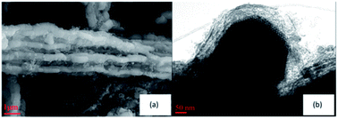 | ||
| Fig. 2 Images of the mesoporous Mn-deficient lithium manganese silicate prepared from an SBA-15 mesoporous SiO2 template (a) SEM image and (b) TEM image. | ||
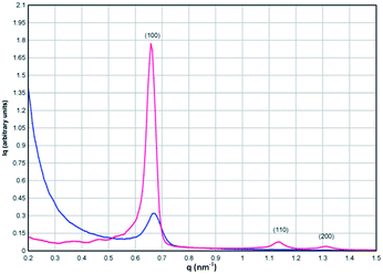 | ||
| Fig. 3 SAXS data for the SBA-15 SiO2 precursor (red) and the mesoporous product (blue) showing retention of the mesoporous order of the precursor in the product phase. | ||
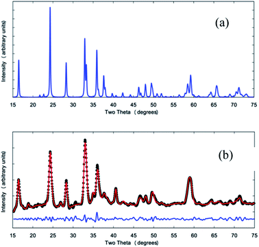
The phase composition and crystal structure of the product phases were analyzed with X-ray diffraction data obtained using a Siemens D5000 and Cu Kα radiation (Fig. 4b and S3†). A simulated X-ray diffraction pattern for the Pmn21 polymorph of Li2MnSiO4 is given in Fig. 4a for comparison.11 Rietveld refinement of crystallographic models was performed with the GSAS program23 suite using the EXPGUI interface24 and the powder X-ray diffraction data of the mesoporous Mn-deficient product. The results show that it consists of a Mn-deficient Li2Mn0.87(3)SiO4 phase (88(5)%) with impurities of MnO (4(1)%) and Li2SiO3 (8(4)%). Peaks of the mesoporous product are in good agreement with the stoichiometric phase in terms of peak position, although the peak intensities differ significantly due to the manganese deficiency. Lattice constants of the mesoporous product are a = 6.307(2) Å, b = 5.389(2) Å and c = 4.979(1) Å, slightly different to those of the standard Pmn21 polymorph of Li2MnSiO4 reported by Dominko et al.11 with a = 6.3109(9) Å, b = 5.3800(9) Å and c = 4.9662(8) Å.
Research shows that it is very difficult to obtain phase-pure samples of Li2MnSiO4 and many samples, in reported studies, contain secondary impurity phases such as MnO and Li2SiO3,19 even though they are electrochemically inactive and undesirable.
FTIR spectra of the mesoporous product were acquired using a Perkin-Elmer FTIR spectrometer with a diamond ATR in transmission mode. The spectra of the SBA-15 precursor and the mesoporous product are shown in Fig. S4.† The strong absorption band of the SBA-15 at ∼1060 cm−1 is replaced in the product by strong bands in the 850–950 cm−1 range, typical of compounds containing SiO44− groups.25 This confirms the chemical conversion of the mesoporous SiO2 precursor into the product phase after calcination.
The electrochemical performance of the mesoporous electrodes was evaluated in Swagelok cells. The working electrode was formed from a slurry of active material: carbon black: PVDF in a ratio of 74![[thin space (1/6-em)]](https://www.rsc.org/images/entities/char_2009.gif) :
:![[thin space (1/6-em)]](https://www.rsc.org/images/entities/char_2009.gif) 13
13![[thin space (1/6-em)]](https://www.rsc.org/images/entities/char_2009.gif) :
:![[thin space (1/6-em)]](https://www.rsc.org/images/entities/char_2009.gif) 13 in N-methylpyrrolidenone (NMP). The electrode slurry was coated onto Al current collectors and dried in vacuum at 80 °C for 12 h. Cathodes were pressed at 15 MPa prior to cell assembly. Typical cathode masses were 1–2 mg. Lithium metal foil was used as the counter electrode. The electrolyte was a solution of 1 M LiPF6 in 1
13 in N-methylpyrrolidenone (NMP). The electrode slurry was coated onto Al current collectors and dried in vacuum at 80 °C for 12 h. Cathodes were pressed at 15 MPa prior to cell assembly. Typical cathode masses were 1–2 mg. Lithium metal foil was used as the counter electrode. The electrolyte was a solution of 1 M LiPF6 in 1![[thin space (1/6-em)]](https://www.rsc.org/images/entities/char_2009.gif) :
:![[thin space (1/6-em)]](https://www.rsc.org/images/entities/char_2009.gif) 1: ethylene carbonate
1: ethylene carbonate![[thin space (1/6-em)]](https://www.rsc.org/images/entities/char_2009.gif) :
:![[thin space (1/6-em)]](https://www.rsc.org/images/entities/char_2009.gif) dimethyl carbonate (Merck Selectilyte). The electrochemical performance was determined using MTI cell cyclers at room temperature at a current rate of 20 mA g−1.
dimethyl carbonate (Merck Selectilyte). The electrochemical performance was determined using MTI cell cyclers at room temperature at a current rate of 20 mA g−1.
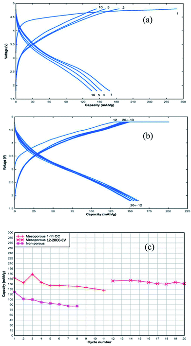
Fig. 5a shows the charge–discharge voltage profiles for cycles 1, 2,5 and 10 recorded in constant current mode between 1.8 and 4.8 V versus Li. The initial discharge capacity, based on the mass of active material including residual carbon from the synthesis (∼5% determined by thermogravimetric analysis), was 170 mA h g−1 with gradual capacity fade with cycling. After 11 cycles the cell was allowed to equilibrate and the cycling regime was changed to constant current–constant voltage cycling (Fig. 5b). The cell was charged to 4.8 V at 20 mA g−1, followed by a voltage hold at 4.8 V until the current dropped to 1/10th of the initial current and then the cell was discharged at 20 mA g−1 to 1.8 V. This change in charging regime resulted in a recovery of the lost capacity and improved capacity retention compared to the constant current cycling regime. The discharge capacity data of the cell containing the mesoporous cathode is shown in Fig. 5c and, for comparison, data for the bulk cathode, prepared under the same conditions, is included. Higher discharge capacity and better capacity retention with cycling was observed for the mesoporous Mn-deficient sample compared to the Mn-deficient bulk sample. TEM analysis of a cathode sample after 20 cycles shows lattice fringes consistent with the ordered, mesoporous structure (Fig. S5†), indicating that this structure is retained. On the other hand, Selected Area Electron Diffraction (SAED) of the cycled mesoporous material (Fig. S6†) shows a pattern consistent with an amorphous material, indicating that the lithium manganese silicate does not retain crystallinity with cycling despite the mesoporous structure.
Conclusions
In this study we demonstrate that a mesoporous lithium manganese silicate can be synthesised from a mesoporous SiO2 precursor using an emulsion synthesis technique. A Mn-deficient product with composition Li2Mn0.87(3)SiO4 was produced that retains the mesoporous order of the silicate precursor. The mesoporous product gives a first discharge capacity of 170 mA h g−1 and good capacity retention using a constant current–constant voltage charging regime at 20 mA g−1. The mesoporous nature of the product allows the electrolyte to penetrate into the bulk of the material to allow rapid lithium ion diffusion into the cathode. This effect results in much improved properties both in terms of capacity and capacity retention for the mesoporous material compared to bulk, non-porous material prepared in the same way. This improvement is observed in spite of amorphization of the lithium manganese silicate with cycling.Acknowledgements
The authors would like to thank Prof. John Drennan and Dr Graeme Auchterlonie, Centre for Microscopy & Microanalysis at the University of Queensland for the TEM data acquisition. We would also like to thank Dr Jennifer Whan of the Advanced Analytical Centre, James Cook University, for the XRD data collection. Thanks also to Dr Kevin Jack, of the Centre for Microscopy & Microanalysis at the University of Queensland for the SAXS data collection. The authors are also grateful to Dr Tao Lu, Griffith University for the synthesis of the SBA-15 precursor used in this study. Thanks to Dr Mark Blackford and Dr Gregory Lumpkin of ANSTO for the TEM and SAED analysis of the cycled mesoporous cathode. We would also like to acknowledge AINSE support for this project on ALNGRA11120.References
- C. Daniel, JOM, 2008, 60, 43–48 CrossRef CAS.
- M. M. Thackeray, C. Wolverton and E. D. Isaacs, Energy Environ. Sci., 2012, 5, 7854–7863 CAS.
- T. Xu, W. Wang, M. L. Gordin, D. H. Wang and D. W. Choi, JOM, 2010, 62, 24–30 CrossRef CAS PubMed.
- A. Manthiram, J. Phys. Chem. Lett., 2011, 2, 176–184 CrossRef CAS.
- Y. Wan and D. Zhao, Chem. Rev., 2007, 107, 2821–2860 CrossRef CAS PubMed.
- C. Liang, Z. Li and S. Dai, Angew. Chem., Int. Ed., 2008, 47, 3696–3717 CrossRef CAS PubMed.
- C. Jiang, E. Hosono and H. Zhou, Nano Today, 2006, 1, 28–33 CrossRef.
- Y. Ye, C. Jo, I. Jeong and J. Lee, Nanoscale, 2013, 5, 4584–4605 RSC.
- F. Jiao and P. G. Bruce, Adv. Mater., 2007, 19, 657–660 CrossRef CAS.
- Y. G. Wang, H. Q. Li, P. He, E. Hosono and H. S. Zhou, Nanoscale, 2010, 2, 1294–1305 RSC.
- R. Dominko, M. Bele, M. Gaberscek, A. Meden, M. Remskar and J. Jamnik, Electrochem. Commun., 2006, 8, 217–222 CrossRef CAS PubMed.
- R. Dominko, M. Bele, A. Kokalj, M. Gaberscek and J. Jamnik, J. Power Sources, 2007, 174, 457–461 CrossRef CAS PubMed.
- A. Kokalj, R. Dominko, G. Mali, A. Meden, M. Gaberscek and J. Jamnik, Chem. Mater., 2007, 19, 3633–3640 CrossRef CAS.
- I. Belharouak, A. Abouimrane and K. Amine, J. Phys. Chem. C, 2009, 113, 20733–20737 CAS.
- Y. X. Li, Z. L. Gong and Y. Yang, J. Power Sources, 2007, 174, 528–532 CrossRef CAS PubMed.
- C. Deng, S. Zhang, B. L. Fu, S. Y. Yang and L. Ma, Mater. Chem. Phys., 2010, 120, 14–17 CrossRef CAS PubMed.
- R. Dominko, J. Power Sources, 2008, 184, 462–468 CrossRef CAS PubMed.
- A. Manthiram, T. Muraliganth and K. R. Stroukoff, Chem. Mater., 2010, 22, 5754–5761 CrossRef.
- R. J. Gummow and Y. He, J. Power Sources, 2014, 253, 315–331 CrossRef CAS PubMed.
- M. Seung-Taek, K. Shinichi, K. Naoaki and C. Hoon-Taek, ChemInform, 2002, 33, 223 Search PubMed.
- T. Dong-Ge, L. Qiong-Yu, W. Ni-Ni, T. Ai-Dong, T. Lian-Xing, H. Ke-Long and J. Xiao-Yang, Mater. Chem. Phys., 2005, 94, 423–428 CrossRef PubMed.
- D. Y. Zhao, Q. S. Huo, J. L. Feng, B. F. Chmelka and G. D. Stucky, J. Am. Chem. Soc., 1998, 120, 6024–6036 CrossRef CAS.
- A. C. Larson and R. B. Von Dreele, Los Alamos National Laboratory Report LAUR, 1994, pp. 86–748 Search PubMed.
- B. H. Toby, J. Appl. Crystallogr., 2001, 34, 210–213 CrossRef CAS.
- K. Zaghib, A. A. Salah, N. Ravet, A. Mauger, F. Gendron and C. M. Julien, J. Power Sources, 2006, 160, 1381–1386 CrossRef CAS PubMed.
Footnote |
| † Electronic supplementary information (ESI) available. See DOI: 10.1039/c3ra47730d |
| This journal is © The Royal Society of Chemistry 2014 |

