Magnetic field assisted growth of highly dense α-Fe2O3 single crystal nanosheets and their application in water treatment

Dong Linab, Biwei Dengab, Stephen A. Sassmanc, Yaowu Huab, Sergey Suslovbd and Gary J. Cheng*abe
aSchool of Industrial Engineering, Purdue University, West Lafayette, IN 47906, USA. E-mail: gjcheng@purdue.edu
bBirck Nanotechnology Center, Purdue University, West Lafayette, IN 47906, USA
cDepartment of Agronomy, Purdue University, West Lafayette, IN 47906, USA
dSchool of Materials Engineering, Purdue University, West Lafayette, IN 47906, USA
eSchool of Mechanical Engineering, Purdue University, West Lafayette, IN 47906, USA

Received 17th December 2013 , Accepted 26th March 2014

First published on 1st April 2014


Abstract

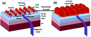
Highly dense 2D nanostructures are desirable in photocatalysis, water treatment and energy storage, due to their high surface to volume areas. This paper describes a novel approach combining thermal stress and magnetic force to generate highly dense α-Fe2O3 nanosheets on the surface of various iron substrates, including plates and powders. This technique involves the thermal oxidation of iron substrates on a hot plate with a magnetic field. The Lorentz force acting on the ions induced by the magnetic field facilitates the lateral growth of nanosheets. This effect results in a highly porous nanostructure consisting of dense 2D nanosheets with extremely large BET surface areas. The application of these nanosheets is explored in water treatment. Electron microscopic studies indicate that these nanosheets show a parabolic relation with time of thermal oxidation for the growth in the width direction. A comparison of heavy metal (As, Cr) ion adsorption of nanosheets and nanowires was also performed, which shows that nanosheets have a much better adsorption rate than nanowires.


Hematite (α-Fe2O3), an n-type semiconductor with a small band gap of 2.1 eV,2 has been extensively studied due to the advantages of high theoretical capacity (1007 mA h g−1), environmentally friendliness, nontoxicity (in bulk form), corrosion-resistance and low cost.3,4 It has been widely applied in the production of gas sensors,4 photocatalysts,5 water treatment,6 magnetic coatings for data storage devices7 and lithium-ion batteries.4 Stimulated by the promising applications of α-Fe2O3 and the novel properties of nanoscale materials,2,4,8–14 various methods such as electrodeposition,15 hydrothermal synthesis,16 sol–gel-mediated reactions,6 solvothermal synthesis,17 direct thermal oxidation,2,6,18 chemical vapor deposition (CVD),19 plasma oxidation20 and plasma-enhanced chemical vapor deposition (PECVD)21 have been developed to fabricate iron oxide nanostructures. In all of these methods, thermal oxidation of metals holds the advantage for commercial application since it is one of the simplest and most scalable approaches.20,22 Large scale of nanowires,7,22 nanoflakes,23 nanorod6 were synthesized by thermal oxidation in different circumstances. The nanowires has been generated by thermal oxidation of pure iron in ambient conditions.24 However, these nanostructures have relatively low area to volume ratio due to the lack of controlled growth in lateral direction. Herein, we report the synthesis of α-Fe2O3 nanosheets by thermal oxidation under magnetic field. With applied magnetic field, nanosheets other than nanowires are formed on the iron plate or powder surface. These highly dense nanosheets arrays will be applied to water treatment to test their functionality to reduce heavy metal ions from water.

During the thermal oxidation under magnetic field, the commercial iron plates and powders were heated in the ambient air. The size of iron plates was cut by 1 cm × 1 cm. These samples were mechanical polished by 0.05 μm-grade aluminum oxide powder.25–28 Two different sizes, micron-sized (average size from 4 to 6 μm) and nano-sized (from 20 to 100 nm), of iron particles were used. The hot plate with magnetic stir function was used as heat source. The magnetic force, which acted on iron ions by magnetic field of hot plate (max magnetic field: 60 mT), was applied on iron powders and plate during heating. The temperature of the hot plate was set to 500 °C to study the effect of time and magnetic field on nanosheets generation. In order to study the magnetic field effects, the width of nanosheets was measured by time evolution. Iron plates and powders were also heated to 500 °C in the ambient air without magnetic field to compare with the nanostructures generated with magnetic field.

The mechanism of nanosheet formation is schematically shown in Fig. 1. During thermal oxidation, different oxidation layers – FeO, Fe3O4 and Fe2O3 from bottom to top – were generated subsequently on iron plate. Compressive thermal stress, which is accumulated by the atomic volume difference between Fe3O4 and Fe2O3 layer, is considered to be the driving force for generating iron oxide nanostructures.2 Iron ions were driven to the sample surface through grain boundaries in Fe2O3 oxidation layer and then move up to the iron oxide nanostructures. As shown in Fig. 1(a), the magnetic field is perpendicular to the ion movement direction, which generates Lorentz force on the iron ions. The Lorentz force is on the nuclei plate and also perpendicular to the ion movement driven by thermal stress. As time increase, nanostructures grow on both directions resulting the generation of iron oxide nanosheet.


image file: c3ra47726f-f1.tif
Fig. 1 Schematic illustration of α-Fe2O3 nanosheet growth under magnetic field: (a) initiation of nanosheet, and (b) growth of nanosheet after several hours.

Fig. 2(a) shows large scale and high density of nanosheet growth on the iron plate due to the magnetic field. High density of iron oxide nanosheets were generated by controlling experimental conditions. The iron plate was placed on the middle of the hot plate. It was heated at 500 °C in the ambient air for 14 hours. The nanosheets show a triangular shape, which is wider at the bottom part. The wider bottom parts of nanosheet are affected by Lorentz force. These nanosheets are wider than iron oxide nanowires generated by thermal oxidation method.2,3,24 The α-Fe2O3 nanosheets and topmost two oxide layers are shown in Fig. 2(b). The Fe2O3 and Fe3O4 layers can be distinguished by discontinuities in grain size and confirmed by EDS study through investigating oxide and iron atomic ratio. The grain size in Fe3O4 layer is flat and large, compared with Fe2O3 layer. Based on the study of Sheikh-Ali et al.29 the grain boundary orientation also migrated by annealing in magnetic field. The grain boundaries were reoriented to parallel to samples surface. Dmitri et al.30 investigated the grain size enlarged by annealing Titanium under magnetic field. After annealing at 1023 K for 240 min under 17 T of magnetic field, the mean grain size increased to 139 μm from 39 μm. These two phenomena are both helpful for accumulating thermal stress.


image file: c3ra47726f-f2.tif
Fig. 2 Nanosheet generation at 500 °C in air for 14 hours under magnetic field, (a) surface morphology and (b) cross sectional view of oxidized layers, (c) TEM image of nanosheet, (d) side view of nanosheet, and (e) Raman spectrum of nanosheets before and after water treatment.

The nanosheet after the processing and its cross section are studied by TEM in Fig. 2(c) and (d), respectively. The diffraction pattern (insert of Fig. 2(c)) shows that the nanosheet is single crystal, which agrees with former iron oxide nanostructures grown by thermal oxidation method. The thickness of nanosheet in Fig. 2(d) is less than 20 nm. The Raman spectrum of nanosheets after thermal oxidation is shown in Fig. 2(f). The strong resonant Raman peaks (at 227, 245, 293, 411, 496, 613, 1318 cm−1) in the range of 150–1500 cm−1 are in good agreement of α-Fe2O3 (a = 5.038 Å, c = 13.772 Å).31 Downshift of the resonant peaks was observed from resonant peaks and it may be due to quantum size effect.2 A weak peak of Fe3O4 at 661 cm−1 was also sometimes detected in the surface, which is agree with the former results.24 This signal may come from the oxide layer of sample surface.

The growth of α-Fe2O3 nanosheets under magnetic field was further investigated by heating for different time at 500 °C. For α-Fe2O3 nanowire generated by thermal oxidation, the growth of α-Fe2O3 nanowire is via diffusion of iron ions from iron oxide layers through stacking fault defects in 〈110〉 direction.22,24 The Fe2O3 oxide layer is topmost and Fe3O4, FeO layers are formed subsequently when heating at elevated temperature.24 They served as the reactants for the inter ion diffusion at high temperature.19 Compressive force accumulated during heating was considered to be the driving force for the iron ion outward to form nanowire.2 Enough time and temperature are needed to accumulate compressive thermal stresses. The temperature range for generating iron oxide nanowires is between 300 °C and 900 °C.3 It needs to be above 300 °C since the rate of stress generation by solid-state phase transformation should sufficient to activate grain boundary diffusion for oxide nanowire growth.2 When above 900 °C,7 lattice diffusion becomes more favorable than grain boundary diffusion. The time evolution of nanosheet growth under magnetic field is shown in Fig. 3 (ref. 32) for 2, 6, 14 and 24 hours, respectively. Fig. 3(a) shows the initial growth morphology of α-Fe2O3 nanosheets. Maximum density of nanosheets was formed on substrate surface after 6 hours of heating. The nanosheet density does not increase after 6 hours. These nanosheets only grow along width and thickness directions.


image file: c3ra47726f-f3.tif
Fig. 3 SEM images of iron oxide nanosheet growth of time evolution: (a) 2 hours, (b) 6 hour, (c) 14 hours and (d) 24 hours, at 500 °C under magnetic field, (e) growth in width of nanosheet as function of time (f) XRD patterns of these samples.

Yuan et al.33 found the oxide layer growth following the parabolic growth law, i.e., x = (2kt)1/2, where x is the thickness of the oxide layer, k is rate constant, and t is the oxidation time. The widths of nanosheets at different heating times were measured by ImageJ in order to study the magnetic effect. As revealed in Fig. 3(e), the mean size of bottom width of nanosheets also follows the parabolic growth law. The growth at the width side proves the effect of magnetic force on nanosheet generation.

The X-ray diffraction (XRD) patterns of as-prepared samples are shown in Fig. 3(f). In the XRD pattern of nanosheets, the relative strong Fe2O3 peak intensities of the diffraction plane (110) and (214) are much higher than other peaks. While 〈110〉 is the direction of growth direction of nanowires for thermal oxidation method, which gives rise to a relatively intense diffraction peak of the (110) plane.31 The rising of (214) peak may be caused by the magnetic field effects.

The high-density nanosheets can be also grown on micro-sized powders through magnetic assisted thermal oxidation process. The α-Fe2O3 nanowires have been grown on micro-sized iron powders.2 In this study, nanosheets were generated under magnetic field at 500 °C for heating 6 hours, as shown in Fig. 4(a). As a comparison, nanowires were generated on micro sized iron powders by heating without magnetic field at 500 °C in air for 6 hours, as shown in Fig. 4(b). The cross-sectional view of nanosheet and nanowire can be seen from Fig. 4(c) and (d), respectively. The height of nanowires ranges from 2 to 3 μm, which are longer than nanosheet. However, nanosheets are much wider than the nanowires, which results in a much higher surface area to volume ratio. The nanosheets are also much a denser than the nanowires. The BET surface area of nanowires and nanosheet were measured, which are shown in Figure 4(e). The BET surface area [m2 g-1] value of nanowire and nanosheet on iron powders was measured 16.484 and 70.866, respectively. It shows that the surface area of the nanosheet is around 4.3 times of nanowire nanostructures, which is a great increase on surface area. The BET value is higher than the γ-Fe2O3 nanostructures in reference 6. It is also higher than commercial TiO2. The measured BET values show that the α-Fe2O3 nanosheet has a good potential for absorbing heavy metal ions.


image file: c3ra47726f-f4.tif
Fig. 4 (a) Nanosheet generation in air for 6 hours and (b) nanowire generation in air for 6 hours under magnetic field, (c) and (d) vertical view of (a) and (b).

Water pollution is one of the major health and environmental challenge for human society.6,34 Removal of heavy metal ions from waste water is an extensive industrial consideration. Currently, the development of using nanomaterials to removal toxic ions from water has attracted much attention. For example, semiconductor nanostructured materials including ZnS, Fe2O3, TiO2 and Cu2O, have been applied studied for water treatment.6,34 Iron oxide nanomaterials have been used to remove toxic ions from waste water. These materials show high capacities than bulk materials because of their high surface area ratio.6 Between all the iron oxide materials, the test results show that α-Fe2O3 has a better adsorption ability than γ-Fe2O3 and Fe3O4.6 However, mass production of nanomaterials with high surface to volume ratio was still a challenge. Thermal oxidation under magnetic field demonstrates its potential for the practical application of water treatment.

Herein, the powders, with iron oxide nanosheet and nanowires respectively, were synthesized for the application of water treatment. Chromium and arsenic are major highly toxic metal ion in waste water and it is of great importance to remove them from water.6 Fig. 5(a) shows the arsenic concentration variation in 10 mL solution as adsorption time increase. Three kinds of iron oxide powders (0.05 g) were added in the solution with arsenic concentration of 10 mg L−1 and the solution was adjusted to pH 4 at room temperature (20 °C). Nanowire, which was grown by thermal oxidation of 24 hours, shows a max of 10% arsenic adsorption. The arsenic adsorption of nanosheet, generated by thermal oxidation under magnetic field of 6 hours, also shows 10% of adsorption after 1 hour water treatment. As a comparison, arsenic can be removed almost 100% after 10 minutes when nanosheets after thermal oxidation for 24 hours were used. For chromium1 adsorption in Fig. 5(b), 0.05 g of nanomaterials, synthesized by thermal oxidation with and without magnetic field respectively, were used for adsorption. 10 mL solution with Cr concentration of 10 mg L−1 was prepared and the pH value was adjusted to 3. The adsorption of Cr for nanowire (after 24 hour thermal oxidation) is around 25% percentage after 10 min, while the adsorption of Cr for nanosheet by thermal oxidation of 6 hours and 24 hours are 50% and 100% after 10 min, respectively. The nanosheet grown after 24 hours by thermal oxidation under magnetic field shows a better adsorption ratio for both chromium and arsenic ions. These results are consistent with the Fig. 3(e) and (f), which shows that the width of nanosheet after 24 hours thermal oxidation under magnetic field is maximized. The phase stability of nanosheet was also measured, which is also shown in Fig. 2(e). The Raman shifts demonstrate that α-Fe2O3 was stable after water treatment.


image file: c3ra47726f-f5.tif
Fig. 5 Adsorption rate of (a) As and (b) Cr by various α-Fe2O3 nanostructures: nanowire 24 hours, nanosheet 6 hours and nanosheet 24 hours.

It was proposed that the mechanism of removing metal and anionic contaminant is surface complexation and ion exchange between nanostructure surface and heavy metal ions.6 Higher surface to volume ratio and better nanostructure stability are beneficial for water treatment. Fig. 6(a) the morphology of magnetic assisted growth of nanosheet after water treatment for 1 hour. It can be seen that the highly dense nanosheet provide extremely large surface per volume geometry for adsorption of chromium and arsenic on to the nanosheet. As a comparison, Fig. 6(b) shows the morphology of nanowires grown without magnetic field assisting, after water treatment for 1 hour. The adsorption of chromium and arsenic on the nanostructures cannot be observed due to both low surface to volume ratio, and not enough mechanical strength during water treatment. The nanowires are broken from the bottom and washed away, while nanosheets still remains their positions. This is because the nanosheets after thermal oxidization is much more mechanically stable due to the lateral growth under magnetic field. This partially contributes to their much higher absorption of heavy metals.


image file: c3ra47726f-f6.tif
Fig. 6 Surface morphology of (a) magnetic assisted growth of nanosheet and (b) nanowire growth without magnetic field assisting after 1 hour water treatment.

In summary, we have demonstrated a procedure combining both thermal oxidation and magnetic field to generate high density and large scale of α-Fe2O3 nanosheet on both iron plate and powders. Both Raman and XRD studies indicated that these nanosheets are α-Fe2O3 nanostructures. The evolution of shape of the nanosheets and grain distribution in the cross section were studied to reveal the effect of magnetic field for the synthesis of α-Fe2O3 nanosheet. Nanosheets (70.866) have much higher BET surface area than nanowires (16.484) and are also more stable during water treatment. These results in excellent adsorption of heavy metal ion in water treatment.

References

  1. J. S. Bunch, S. S. Verbridge, J. S. Alden, A. M. van der Zande, J. M. Parpia, H. G. Craighead and P. L. McEuen, Nano Lett., 2008, 8, 2458–2462 CrossRef CAS PubMed.
  2. Y. Y. Fu, R. M. Wang, J. Xu, J. Chen, Y. Yan, A. V. Narlikar and H. Zhang, Chem. Phys. Lett., 2003, 379, 373–379 CrossRef CAS PubMed.
  3. P. Hiralal, H. E. Unalan, K. G. U. Wijayantha, A. Kursumovic, D. Jefferson, J. L. MacManus-Driscoll and G. A. J. Amaratunga, Nanotechnology, 2008, 19, 455608 CrossRef CAS PubMed.
  4. J. Chen, L. Xu, W. Li and X. Gou, Adv. Mater., 2005, 17, 582–586 CrossRef CAS.
  5. J. S. Jang, H. G. Kim, V. R. Reddy, S. W. Bae, S. M. Ji and J. S. Lee, J. Catal., 2005, 231, 213–222 CrossRef CAS PubMed.
  6. L. S. Zhong, J. S. Hu, H. P. Liang, A. M. Cao, W. G. Song and L. J. Wan, Adv. Mater., 2006, 18, 2426–2431 CrossRef CAS.
  7. T. Tepper, F. Ilievski, C. A. Ross, T. R. Zaman, R. J. Ram, S. Y. Sung and B. J. H. Stadler, J. Appl. Phys., 2003, 93, 6948–6950 CrossRef CAS PubMed.
  8. S. F. Hasany, N. H. Abdurahman, A. R. Sunarti and R. Jose, Curr. Nanosci., 2013, 9, 561–575 CrossRef CAS.
  9. M. L. Kahn, A. Glaria, C. Pages, M. Monge, L. Saint Macary, A. Maisonnat and B. Chaudret, J. Mater. Chem., 2009, 19, 4044–4060 RSC.
  10. M. I. Dar and S. Shivashankar, RSC Adv., 2014, 4, 4105–4113 RSC.
  11. L. Yuan, R. Cai, J. I. Jang, W. Zhu, C. Wang, Y. Wang and G. Zhou, Nanoscale, 2013, 5, 7581–7588 RSC.
  12. L. Yuan, Q. Jiang, J. Wang and G. Zhou, J. Mater. Res., 2012, 27, 1014–1021 CrossRef CAS.
  13. L. Yuan, Y. Wang, R. Cai, Q. Jiang, J. Wang, B. Li, A. Sharma and G. Zhou, J. Mater. Sci. Eng. B, 2012, 177, 327–336 CrossRef CAS PubMed.
  14. R. Cai, T. Li, Y. Wang, C. Wang, L. Yuan and G. Zhou, J. Nanopart. Res., 2012, 14, 1–11 CrossRef.
  15. L. Y. Zhang, D. S. Xue, X. F. Xu, A. B. Gui and C. X. Gao, J. Phys.: Condens. Matter, 2004, 16, 4541 CrossRef CAS.
  16. D. Chen and L. Gao, Chem. Phys. Lett., 2004, 395, 316–320 CrossRef CAS PubMed.
  17. J. Jin, S. Ohkoshi and K. Hashimoto, Adv. Mater., 2004, 16, 48–51 CrossRef CAS.
  18. Y. M. Zhao, Y.-H. Li, R. Z. Ma, M. J. Roe, D. G. McCartney and Y. Q. Zhu, Small, 2006, 2, 422–427 CrossRef CAS PubMed.
  19. Y. L. Chueh, M. W. Lai, J. Q. Liang, L. J. Chou and Z. L. Wang, Adv. Funct. Mater., 2006, 16, 2243–2251 CrossRef CAS.
  20. U. Cvelbar, Z. Chen, M. K. Sunkara and M. Mozetič, Small, 2008, 4, 1610–1614 CrossRef CAS PubMed.
  21. F. Liu, P. J. Cao, H. R. Zhang, J. F. Tian, C. W. Xiao, C. M. Shen, J. Q. Li and H. J. Gao, Adv. Mater., 2005, 17, 1893–1897 CrossRef CAS.
  22. C. J. Love, J. D. Smith, Y. Cui and K. K. Varanasi, Nanoscale, 2011, 3, 4972–4976 RSC.
  23. P. M. Rao and X. Zheng, Nano Lett., 2009, 9, 3001–3006 CrossRef CAS PubMed.
  24. A. Nasibulin, S. Rackauskas, H. Jiang, Y. Tian, P. Mudimela, S. Shandakov, L. Nasibulina, S. Jani and E. Kauppinen, Nano Res., 2009, 2, 373–379 CrossRef CAS PubMed.
  25. D. Lin, M. Y. Zhang, C. Ye, Z. Liu, C. R. Liu and G. J. Cheng, Appl. Surf. Sci., 2012, 258, 4254–4259 CrossRef CAS PubMed.
  26. D. Lin, Y. Yang and G. J. Cheng, Appl. Surf. Sci., 2013, 283, 924–929 CrossRef CAS PubMed.
  27. D. Lin, S. Suslov, C. Ye, Y. Liao, C. R. Liu and G. J. Cheng, Appl. Surf. Sci., 2011, 113, 133509 Search PubMed.
  28. D. Lin, C. Ye, Y. Liao, S. Suslov, R. Liu and G. J. Cheng, J. Appl. Phys., 2013, 113, 133509 CrossRef PubMed.
  29. A. D. Sheikh-Ali, D. A. Molodov and H. Garmestani, Scr. Mater., 2003, 48, 483–488 CrossRef CAS.
  30. C. B. Dmitri, A. Molodov, P. J. Konijnenberg, L. A. Barrales-Mora and V. Mohles, Mater. Trans., 2007, 48, 2800–2808 CrossRef.
  31. X. Wen, S. Wang, Y. Ding, Z. L. Wang and S. Yang, J. Phys. Chem. B, 2004, 109, 215–220 CrossRef PubMed.
  32. M. Terrones, O. Martín, M. González, J. Pozuelo, B. Serrano, J. C. Cabanelas, S. M. Vega-Díaz and J. Baselga, Adv. Mater., 2011, 23, 5302–5310 CrossRef CAS.
  33. L. Yuan, Y. Wang, R. Mema and G. Zhou, Acta Mater., 2011, 59, 2491–2500 CrossRef CAS PubMed.
  34. H. Chen and J. He, J. Phys. Chem. C, 2008, 112, 17540–17545 CAS.

This journal is © The Royal Society of Chemistry 2014