Significant enhancement of visible up-conversion emissions of Y2O2S:Er3+ phosphors by Mn2+ sensitizing under 1550 nm excitation

Shuanglong Yuana, Huidan Zeng*a, Xuanshun Wua, Zhao Liuab, Jing Rena, Guorong Chena, Zhaofeng Wangc and Luyi Sun*c
aKey Laboratory for Ultrafine Materials of Ministry of Education, School of Materials Science and Engineering, East China University of Science and Technology, Shanghai 200237, China. E-mail: hdzeng@ecust.edu.cn; Fax: +86-21-64253395; Tel: +86-21-64253395
bState Key Laboratory of Luminescent Materials and Devices, South China University of Technology, Guangzhou, 510640, China
cDepartment of Chemical & Biomolecular Engineering and Polymer Program, Institute of Materials Science, University of Connecticut, Storrs, Connecticut 06269, USA. E-mail: luyi.sun@uconn.edu; Fax: +1-860-486-4745; Tel: +1-860-486-6895

Received 15th December 2013 , Accepted 25th March 2014

First published on 25th March 2014


Abstract

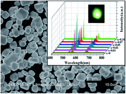
A novel up-conversion (UC) emission route of Er3+ by Mn2+ sensitizing in a Y2O2S:Er3+ phosphor prepared via a high-temperature solid-state reaction method is reported here. This methodology resulted in a significant enhancement of visible up-conversion emission by 1550 nm laser diode excitation. By co-doping Mn2+, the visible (red and green) UC emission intensity, which is assigned to the transitions of 4F9/24I15/2 (670 nm), 4S3/24I15/2 (547 nm), 2H11/24I15/2 (528 nm) of Er3+, was 2 to 3 times higher than that of the Mn2+-free one. As the concentration of Mn2+ was increased, the visible UC emission intensity was enhanced and then reduced. The phosphor powders were well crystallized in a hexagonal shape with an average size of ca. 2 μm. Based on the results of the luminescence spectra, energy matching conditions and three-photon process dependence on excitation power, a possible UC mechanism is proposed. The proposed sensitizing route may lead to a promising step towards high-intensity UC emissions of rare-earth ion doped phosphors.


Introduction

The lanthanide infrared (IR)-to-visible up-conversion (UC) phenomenon has attracted great attention for its potential applications in IR pumped imaging, bio-imaging, displays, lasers, and solar cells.1–3 With the advent of low cost, readily available and powerful IR laser diodes, there has been a renewed interest in UC. Notably, the trivalent Er3+ ions are considered the potential up-convertors for red, green, and blue emissions because of their rich energy levels, which well fit the excitation of commercial IR laser diodes. However, Er3+ ions doped samples usually exhibit low UC emission intensity when excited by the lights in the range of 1000–1600 nm, which strongly limits the application and development of these UC phosphors in the infrared wavelength region. Yb3+ ions have been virtually exclusively used as a trivalent rare earth sensitizer at the 980 nm excitation, but they are not effective in the 1000–1600 nm excitation range.4–6 In particular, Yb3+ ions perform poorly when excited by a commercial 1550 nm laser diode, which is one of the most widely used laser diodes on market currently. In order to improve the UC emission intensity at the 1550 nm excitation, we must seek alternative efficient sensitizers.

Non-rare-earth ions, which exhibit excellent performance, have been frequently used as co-dopants to improve the phosphor optical properties.7–9 As reported in the literature,10–14 UC of rare earth (RE)-transition metal (TM) ions co-doping system benefits from the combined advantages of specific energy levels of RE ions and tunable energy levels of TM ions, which are very attractive for a wide range of applications.15–17 The choice of different hosts and RE/TM dopants may result in novel and desirable UC properties.18

TM ions have been widely used in luminescent materials. Among them, Mn2+, as a typical luminescent center, has attracted high interest for various applications because of its unique optical properties.19–24 Mn2+ has been studied in various inorganic hosts covering a wide emission range from blue to red.25 Recently, green UC emission of Mn2+ at room temperature was observed in non-halide material LaMgAl11O19:Yb3+, Mn2+.15,17 The UC luminescence of the Er3+/Mn2+ pair was extensively investigated in Yb3Al5O12 at low temperatures under IR laser excitation.26 Compared to other host matrices (e.g., chalcogenides, fluorides, oxides), the commercial phosphor host Y2O2S exhibits favorable chemical stability as well as higher luminescent efficiency due to its moderate phonon energies (about 520 cm−1), wide band gap, and high energy transfer efficiency.27 Thus, Y2O2S is expected to exhibit UC when co-doped with Er3+ and Mn2+ due to the crystal local field.

In this work, Er3+/Mn2+ co-doped Y2O2S phosphors were prepared, with an aim to develop a novel route that can significantly enhance the visible UC emission intensity by the 1550 nm excitation. To the best of our knowledge, this is the first report on the 1550 nm excited UC spectral studies in Er3+/Mn2+ co-doped Y2O2S phosphors.

Experimental

Sample preparation

The phosphors were prepared by the high-temperature solid-state reaction method. Stoichiometric amounts of starting materials Y2O3 (99.99%), Er2O3 (99.99%) and S (99.999%), MnCO3 (analytical grade) and Na2CO3 (analytical grade) were thoroughly mixed in an agate mortar. The concentrations of these rare earth oxides and MnCO3 were formulated according to the chemical formula of (Y0.95−xEr0.05Mnx)2O2S (x = 0, 0.01, 0.03, 0.05, 0.07, 0.10) and (Y0.97Mn0.03)O2S (denoted as YM1). The Na2CO3 acted as a flux for the sintering process. The pre-determined amount of the starting materials were mixed, and sintered at 1100 °C for 3 h using an alumina crucible with an alumina cover in carbon reducing atmosphere,28 and then cooled down to room temperature in the furnace. The sintered samples were further treated by washing with dilute hydrochloric acid (pH ≈ 1) and distilled water several times. The washed powders were subsequently filtered and dried. The resultant fine powders were collected for characterization.

Characterization

The phosphor samples were characterized by X-ray diffraction (XRD) (Rigaku, D/Max-RB, Cu Kα radiation, λ = 0.15406 nm). Electron paramagnetic resonance (EPR) spectra of the samples were recorded on a Bruker EMX-8/2.7 EPR spectrometer operating in the X-band frequency (9.877 GHz). The morphology of the phosphor samples was examined by a field emission scanning electron microscope (FE-SEM, S-4800, Hitachi High-Technologies). Absorption spectra of the samples were acquired on a UV-Vis-NIR spectrophotometer (CARY 500, Varian Company). The UC luminescence spectra were recorded at room temperature on an Edinburgh FLS920P spectrometer, excited by a tunable 1550 nm semiconductor laser diode (0–500 mW).

Results and discussion

The XRD patterns of the as-synthesized samples with various Mn2+ ions concentrations are shown in Fig. 1. According to the XRD patterns, the phases of all samples are hexagonal Y2O2S (JCPDS # 24-1424) without any detectable impurity, which suggests that the crystalline hexagonal phase of Y2O2S samples were obtained by the high-temperature solid-state reaction method and their structural morphology was not influenced by the addition of Mn2+ ions. Fig. 1 also shows that the Mn2+-doping approach does not result in phase transformation, but the 2θ values of the XRD peaks for all Er/Mn co-doped samples are slightly lower than those of typical hexagonal Y2O2S. Y2O2S crystallizes in space group P[3 with combining macron]m1 (164) with the metal ions at the Wyckoff site 2d with 3m (C3v) point group symmetry, surrounded by four oxygen and three sulfur ions.29 The calculated cell parameters (a, b, c) (listed in Table 1) of the samples become slightly larger, indicating that the Mn2+-doped ions have a weak influence on the host crystal lattice.
image file: c3ra47645f-f1.tif
Fig. 1 XRD patterns of (Y0.95−x)2O2S:Er0.1,Mnx (x = 0, 0.01, 0.03, 0.05, 0.07, 0.10) samples and standard Y2O2S crystal.
Table 1 The unit cell parameters of the samples (Y0.95−xEr0.05Mnx)2O2S (x = 0, 0.01, 0.03, 0.05, 0.07, 0.10) compared with the standard trigonal Y2O2S
Sample no. Formula Unit cell parameters
a b c
Reference Y2O2S 3.785 3.785 6.571
YEM0 (Y0.95Er0.05)2O2S 3.789 3.789 6.609
YEM1 (Y0.95−xEr0.05Mn0.01)2O2S 3.799 3.799 6.616
YEM2 (Y0.95−xEr0.05Mn0.03)2O2S 3.806 3.806 6.621
YEM3 (Y0.95−xEr0.05Mn0.05)2O2S 3.812 3.812 6.625
YEM4 (Y0.95−xEr0.05Mn0.07)2O2S 3.817 3.817 6.627
YEM5 (Y0.95−xEr0.05Mn0.10)2O2S 3.824 3.824 6.628


Generally, there are two possible sites for the doped Mn2+: the interstices or the sites of Y3+ (the radius difference is less than 30%).30 From the increase of the cell parameters (a, b, c) as shown in Table 1, one can conclude that the occupy sites should be the interstices because the ionic size of Mn2+ is significantly smaller than that of Y3+. This is also consistent with a recent report by Yang et al.,31 which suggested that Mn2+ could partially enter interstitial sites when Mn2+ cations were doped into SrTiO3 due to the relatively large difference in ionic radius between Sr2+ and Mn2+. To compensate the charge of Mn2+ in the interstitial sites, some O2− or S2− should also exist there. Hence, luminescence defects will be produced during the interstitial process of Mn2+ (assigned as I(Mn)).32,33 These defects would introduce some new energy levels in the energy band of Y2O2S host matrix, which has significant influence on the photoluminescence properties of the phosphors.34,35

The prepared samples with various Mn2+ concentrations exhibit similar particle size and size distribution. Fig. 2 shows a representative SEM image of the as-fabricated (Y0.92Er0.05Mn0.03)2O2S sample. The sample is of hexagonal morphology with smooth surface and an average grain size is ca. 2 μm.


image file: c3ra47645f-f2.tif
Fig. 2 SEM image of (Y0.92Er0.05Mn0.03)2O2S sample.

EPR was further utilized to determine the existence of Mn2+. Fig. 3 presents the EPR spectra of (Y0.95−xEr0.05Mn0.03)2O2S and (Y0.94Mn0.03)2O2S samples. The resonance signals at a g value of ca. 2.0 were observed, in good agreement with the characteristic electron spin S and nuclear spin I of Mn2+ (S = I = 5/2).36 Therefore, the EPR results support that Mn2+ ions have been successfully doped into the Y2O2S host lattice.


image file: c3ra47645f-f3.tif
Fig. 3 EPR spectra of (Y0.92Er0.05Mn0.03)2O2S and (Y0.97Mn0.03)2O2S samples.

The absorption spectra of the samples with various Mn2+ concentrations are shown in Fig. 4, from which several absorption bands of Er3+ in all Er or Er/Mn co-doped samples can be observed. These absorption bands can be attributed to the transitions of 4I15/24G11/4 (381 nm), 4I15/24F7/2 (495 nm), 4I15/22H11/2 (524 nm), 4I15/24F9/2 (661 nm), 4I15/24I9/2 (808 nm), 4I15/24I11/2 (980 nm), 4I15/24I13/2 (1550 nm) of Er3+.37 By increasing Mn2+ concentration from 0 to 10.0 mol%, there was little influence on the entire absorption in the VIS-IR range. The zoomed absorption spectrum of the Mn2+ single-doped sample YM1 is shown in the inset of Fig. 4, from which one can observe an obvious absorption band in the range of 800 to 1000 nm wavelength. This absorption band does not match any Mn2+ energy level according to Tanabe–Sugano diagram for d5 ions,38 which suggests that the band probably originates from I(Mn). Moreover, such a band overlaps with the Er3+ doped samples.


image file: c3ra47645f-f4.tif
Fig. 4 Absorption spectra of (Y0.95−xEr0.05Mnx)2O2S (x = 0, 1.0, 3.0, 5.0, 7.0, 10.0 mol%).

Room temperature UC luminescence spectra of (Y0.97Mn0.03)2O2S, (Y0.95Er0.05)2O2S and (Y0.92Er0.05Mn0.03)2O2S samples when excited at 980 nm are shown in Fig. 5. It is interesting to note that the sample doped with Mn2+ only exhibited a broad non-symmetric emission band peaking at ca. 830 nm accompanied with a weak hump centered at ca. 771 nm. This is in accordance with the absorption spectrum of (Y0.97Mn0.03)2O2S. Such broad emission band only exists in Mn2+ single-doped samples, but is not shown in the Er3+/Mn2+ co-doped samples. Therefore, it is concluded that doping of Mn2+ would introduce a new energy level (assigned as E[Mn]) at ca. 830 nm. This energy level overlaps with I9/2 level of Er3+, which can potentially facilitate the energy transfer from E[Mn] to Er3+ in Er3+/Mn2+ co-doped samples.


image file: c3ra47645f-f5.tif
Fig. 5 UC luminescence spectra of samples excited at 980 nm.

Room temperature UC luminescence spectra of the samples with various Mn2+ concentrations when excited at 1550 nm are shown in Fig. 6. The inset shows a photograph of the UC emission (Y0.92Er0.05Mn0.03)2O2S upon 50 mW excitation at 1550 nm. In Fig. 6(a), the emission spectra in the 520–680 nm range are characterized by an intense green band at ca. 547 nm followed by an intense red band at ca. 670 nm. These emissions are strong to the naked eyes. The emission bands are observed in three regions that are composed of several overlapping peaks due to the crystal-field splitting, and can be attributed to the transitions 4F9/24I15/2 (670 nm), 4S3/24I15/2 (547 nm), 2H11/24I15/2 (528 nm) of Er3+. The sample without Mn2+ exhibits the lowest emission intensity among all samples. During the measurement, we also found that doping of Mn2+ did not result in peak shape or position evolution. And, Mn2+ single-doped sample (Y0.97Mn0.03)2O2S has no UC emission, which means that the introduced new energy level E[Mn] by Mn2+ does not match the energy of 1550 nm. In Fig. 6(b), as the concentration of Mn2+ ions increases from 1.0 to 3.0 mol%, the emission intensity increases gradually. It is noticeable that further increasing the concentration of Mn2+ to 10.0 mol% remarkably decreases the intensity of both green and red emission bands. The involved mechanism will be further discussed in the following paragraphs. It should be noted that the UC emission intensity of (Y0.92Er0.05Mn0.03)2O2S phosphor was 2–3 times as intense as (Y0.95Er0.05)2O2S.


image file: c3ra47645f-f6.tif
Fig. 6 (a) UC luminescence spectra of (Y0.95−xEr0.05Mnx)2O2S (x = 0, 1.0, 3.0, 5.0, 7.0, 10.0 mol%) samples excited at 1550 nm. The inset is a photograph of the UC emission of (Y0.92Er0.05Mn0.03)2O2S under 50 mW excitation power. (b) Variations of UC emission (528, 548 and 670 nm) intensity as a function of Mn2+ concentration.

The dependence of the pumping power and luminescence intensity of (Y0.92Er0.05Mn0.03)2O2S sample is shown in Fig. 7, in which the number of photons n determined from the slope coefficient of the linear fitted lines is 2.21, 2.83, 2.97 monitored at the emission peak wavelength 670, 548 and 524 nm, respectively. This result indicates that the UC luminescence is attributed to a three-photon absorption (TPA) mechanism, which is consistent with the literature.2


image file: c3ra47645f-f7.tif
Fig. 7 Log–log plot of the UC emission intensities as a function of the 1550 nm excitation power for (Y0.92Er0.05Mn0.03)2O2S sample.

Based on the results of the luminescence spectra, the energy matching conditions, and the TPA processes, the following possible UC mechanism is proposed as shown in Fig. 8. Initially, Er3+ can be directly excited from ground state to 4I13/2 level via the absorption of a 1550 nm photon, and it can be further excited to 4I9/2 level by absorbing another 1550 nm photon. The electron of Er3+ at 4I9/2 level can be further excited to a higher energy level (2H11/2), generating the emission bands at 528, 548, and 670 nm (2H11/24I15/2, 4S3/2 → 4I15/2, and 4F9/2 → 4I15/2 transitions, respectively) through non-radiation relaxation. For this reason, the Er3+ doped sample can exhibit UC luminescence. When Mn2+ was co-doped in the matrix, it turned to be different because I(Mn) could act as an efficient sensitizing center. Since the energy of 4I9/2 level of Er3+ is slightly larger than that of the E[Mn] level originated from I(Mn), the energy transfer (ET) process from Er3+ to I(Mn) dominates in the excitation of E[Mn] level (ca. 830 nm, which can be reflected from Fig. 5). As the E[Mn] matches well with 4I13/22H11/2, part of the populated 4I13/2 level is excited to the 2H11/2 state from the I(Mn) emission channel. Similar energy transfer between Er3+ and Mn2+ was also reported in a recent research.39 After these excited state processes, de-excitation accumulates electrons in different excited states and the intensity of emission depends on the electron density at that particular level as well as the non-radiative contribution to the emission band. The level 2H11/2 acts as a meta-stable level and the emission from 2H11/2 to 4I15/2 results in 528 nm emission. Since the 2H11/2 level couples to the 4S3/2 level by lattice phonon relaxation between closely spaced energy levels, the level 4S3/2 act as a meta-stable level and the emission from 4S3/2 to 4I15/2 results in 547 nm emission. Fractional populations accumulated in level 4F9/2 decays to 4I15/2, giving rise to emissions at 670 nm. In oxysulfide hosts, because of the weak lattice phonon relaxation, the non-radiative contribution to 547, 670 nm emission bands forms the energy gap between 4S3/24F9/2 (Er3+).


image file: c3ra47645f-f8.tif
Fig. 8 Proposed UC luminescence mechanism of Er3+, Mn2+ co-doped Y2O2S excited at 1550 nm.

The optimal doping concentration of Mn2+ is found to be 3.0 mol%, and the corresponding emission intensity is 2–3 times higher than that of (Y0.95Er0.05)2O2S. By Mn2+ sensitizing in Y2O2S:Er3+ phosphor, the visible UC emission intensity enhances significantly due to the increase of the photon numbers of the 2H11/2 (Er3+) level. With the further increase of Mn2+ ions, however, the intensity of luminescence grows less intense. Similar phenomena have been widely reported for the Mn2+ ions doped glasses,40,41 and are ascribed to the concentration quenching effect that is due to the cross-relaxation caused by the interactions of Mn2+ ions.

Conclusions

The 1550 nm excited UC processes of Er3+/Mn2+ co-doped Y2O2S phosphors prepared by a high-temperature solid-state reaction method is reported for the first time. Through Mn2+ ions doping, hexagonal phase of the samples remains intact, and their average size is ca. 2 μm. By co-doping Mn2+, Y2O2S:Er3+ samples exhibit strong green and red UC emission under the excitation of 1550 nm laser. The UC emission intensity of (Y0.92Er0.05Mn0.03)2O2S phosphor is 2–3 times higher than that of (Y0.95Er0.05)2O2S. It is hoped that this report will stimulate further discoveries of other UC materials with the designed structure and desirable optical functionalities.

Acknowledgements

This work is financially supported by the Natural Science Foundation of Shanghai (12ZR1407600, 11ZR1409300), the Fundamental Research Funds for the Central Universities, the Shanghai Leading Academic Discipline Project (B502), and the Open Fund of the State Key Laboratory of Luminescent Materials and Devices (South China University of Technology). L.S. acknowledges the National Science Foundation (Partnerships for Research and Education in Materials, DMR-1205670), Air Force Office of Scientific Research (no. FA9550-12-1-0159), and a Faculty Large Grant from the University of Connecticut for partial support of this project.

References

  1. I. Etchart, I. Hernández, A. Huignard, M. Bérard, W. P. Gillin, R. J. Curry and A. K. Cheetham, J. Mater. Chem., 2011, 21, 1387–1394 RSC.
  2. G. Kumar, M. Pokhrel and D. Sardar, Mater. Lett., 2012, 68, 395–398 CrossRef CAS PubMed.
  3. C. Yuan, G. Chen, P. N. Prasad, T. Y. Ohulchanskyy, Z. Ning, H. Tian, L. Sun and H. Ågren, J. Mater. Chem., 2012, 22, 16709–16713 RSC.
  4. A. Shooshtari, P. Meshkinfam, T. Touam, M. P. Andrews and S. I. Najafi, Opt. Eng., 1998, 37, 1188–1192 CrossRef CAS PubMed.
  5. P. M. Peters, D. S. Funk, A. P. Peskin, D. L. Veasey, N. A. Sanford, S. N. Houde-Walter and J. S. Hayden, Appl. Opt., 1999, 38, 6879 CrossRef CAS.
  6. Z. Wang, Y. Wang, Y. Li and H. Zhang, J. Mater. Res., 2011, 26, 693–696 CrossRef CAS.
  7. M. Chong, K. Pita and C. Kam, Appl. Phys. A: Mater. Sci. Process., 2004, 79, 433 CrossRef CAS PubMed.
  8. J. Li, Y. Wang and B. Liu, J. Lumin., 2010, 130, 981 CrossRef CAS PubMed.
  9. Q. Yu, H. Zeng, Z. Liu, J. Ren, G. Chen, Z. Wang and L. Sun, J. Alloys Compd., 2014, 590, 92–95 CrossRef CAS PubMed.
  10. N. Sonoyama, K. Kawamura, A. Yamada and R. Kanno, J. Lumin., 2008, 128, 1679–1683 CrossRef CAS PubMed.
  11. G. Gasparotto, S. A. M. Lima, M. R. Davolos, J. A. Varela, E. Longo and M. A. Zaghete, J. Lumin., 2008, 128, 1606–1610 CrossRef CAS PubMed.
  12. C. Liu, Y. Wang, Y. Hu, R. Chen and F. Liao, J. Alloys Compd., 2009, 470, 473–476 CrossRef CAS PubMed.
  13. Y. Hu, W. Zhuang, H. Ye, S. Zhang, Y. Fang and X. Huang, J. Lumin., 2005, 111, 139–145 CrossRef CAS PubMed.
  14. S. Ye, Y.-j. Li, D.-c. Yu, G.-p. Dong and Q.-Y. Zhang, J. Mater. Chem., 2011, 21, 3735–3739 RSC.
  15. B. M. van der Ende, L. Aarts and A. Meijerink, Phys. Chem. Chem. Phys., 2009, 11, 11081–11095 RSC.
  16. R. Martín-Rodríguez, R. Valiente and M. Bettinelli, Appl. Phys. Lett., 2009, 95, 091913 CrossRef PubMed.
  17. R. Martín-Rodríguez, R. Valiente, F. Rodríguez, F. Piccinelli, A. Speghini and M. Bettinelli, Phys. Rev. B: Condens. Matter Mater. Phys., 2010, 82, 075117 CrossRef.
  18. J. Suyver, A. Aebischer, D. Biner, P. Gerner, J. Grimm, S. Heer, K. Krämer, C. Reinhard and H. Güdel, Opt. Mater., 2005, 27, 1111–1130 CrossRef CAS PubMed.
  19. R. Bhargava, D. Gallagher, X. Hong and A. Nurmikko, Phys. Rev. Lett., 1994, 72, 416–419 CrossRef CAS.
  20. A. Morell and N. El Khiati, J. Electrochem. Soc., 1993, 140, 2019–2022 CrossRef CAS PubMed.
  21. A. A. Bol and A. Meijerink, J. Phys. Chem. B, 2001, 105, 10203–10209 CrossRef CAS.
  22. T. Ohtake, N. Sonoyama and T. Sakata, Chem. Phys. Lett., 1998, 298, 395–399 CrossRef CAS.
  23. G. Tian, Z. Gu, L. Zhou, W. Yin, X. Liu, L. Yan, S. Jin, W. Ren, G. Xing and S. Li, Adv. Mater., 2012, 24, 1226–1231 CrossRef CAS PubMed.
  24. H. Zeng, Q. Yu, Z. Wang, L. Sun, J. Ren, G. Chen and J. Qiu, J. Am. Ceram. Soc., 2013, 96, 2476–2480 CrossRef CAS.
  25. G. Blasse and A. Bril, Philips Tech. Rev., 1970, 31, 304–334 CAS.
  26. Z. P. Li, B. Dong, Y. Y. He, B. S. Cao and Z. Q. Feng, J. Lumin., 2012, 132, 1646–1648 CrossRef CAS PubMed.
  27. G. F. J. Garlick and C. L. Richards, J. Lumin., 1974, 9, 432–439 CrossRef CAS.
  28. X. Wu, H. Zeng, Q. Yu, C. Fan, J. Ren, S. Yuan and L. Sun, RSC Adv., 2012, 2, 9660–9664 RSC.
  29. M. Raukas, K. C. Mishra, C. Peters, P. C. Schmidt, K. H. Johnson, J. Choi and U. Happek, J. Lumin., 2000, 87–89, 980–982 CrossRef CAS.
  30. Z. Wang, Y. Wang, Y. Li and B. Liu, J. Electrochem. Soc., 2010, 157, J125–J129 CrossRef CAS PubMed.
  31. H. Yang, P. G. Kotula, Y. Sato, M. Chi, Y. Ikuhara and N. D. Browning, Mater. Res. Lett., 2014, 2, 16–22 CrossRef CAS.
  32. J. Iqbal, X. Liu, A. Majid, D. Yu and R. Yu, Europhys. Lett., 2009, 87, 57004 CrossRef.
  33. Z. Wang, Y. Wang, Y. Li and B. Liu, J. Alloys Compd., 2011, 509, 343–346 CrossRef CAS PubMed.
  34. C. Zhang and J. Lin, Chem. Soc. Rev., 2012, 41, 7938–7961 RSC.
  35. Y. Li, Z. Wang, L. Sun, Z. Wang, S. Wang, X. Liu and Y. Wang, Mater. Res. Bull., 2014, 50, 36–41 CrossRef CAS PubMed.
  36. Q. Yan, Y. Liu, G. Chen, N. Da and L. Wondraczek, J. Am. Ceram. Soc., 2011, 94, 660–662 CrossRef CAS.
  37. E. Chukova, Anti-Stokes Luminescence and Its Potential Applications, Sovetskoe Radio, Moscow, 1980 Search PubMed.
  38. Y. Tanabe and S. Sugano, J. Phys. Soc. Jpn., 1954, 9, 766–779 CrossRef CAS.
  39. G. Tian, Z. Gu, L. Zhou, W. Yin, X. Liu, L. Yan, S. Jin, W. Ren, G. Xing, S. Li and Y. Zhao, Adv. Mater., 2012, 24, 1226–1231 CrossRef CAS PubMed.
  40. M. Kawano, H. Takebe and M. Kuwabara, Opt. Mater., 2009, 32, 277–280 CrossRef CAS PubMed.
  41. J. Flores, G. Caldino, A. Hernández, G. Camarillo, B. Cabrera, H. Del Castillo, A. Speghini, M. Bettinelli and S. Murrieta, Phys. Status Solidi C, 2007, 4, 922–925 CrossRef PubMed.

This journal is © The Royal Society of Chemistry 2014
Click here to see how this site uses Cookies. View our privacy policy here.