An ultrafast microwave approach towards multi-component and multi-dimensional nanomaterials

Zhen Liua, Lin Zhangb, Selcuk Poyraza, James Smitha, Vinod Kushvahac, Hareesh Tippurc and Xinyu Zhang*a
aDepartment of Polymer & Fiber Engineering, Auburn University, Auburn, AL 36849, USA. E-mail: xzz0004@auburn.edu
bMaterials Research and Education Center, Auburn University, Auburn, AL 36849, USA
cDepartment of Mechanical Engineering, Auburn University, Auburn, AL 36849, USA

Received 27th November 2013 , Accepted 23rd January 2014

First published on 23rd January 2014


Abstract

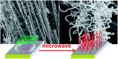
Sea-urchin like, multi-component, 3-D nanostructures have been synthesized using a microwave assisted approach, which is called the “PopTube” method. This microwave approach has the advantages of high-efficiency and selective heating, simple experimental conditions and instrument setups, which provides a facile and ultrafast technique to obtain three dimensional nanomaterial growth on various engineering material substrates. It takes at most 15–30 s to grow carbon nanotubes (CNT) on top of a wide selection of substrate surfaces, such as indium tin oxide (ITO) nanopowders/glass, carbon fibers and milled glass fibers. Moreover, metal oxide nanostructures such as iron oxide can also be produced via this process without any extra chemical reagents. The process can be performed with a kitchen microwave oven, at room temperature and ambient conditions, without the need for any gas protection or high vacuum. Multi-component and multi-dimensional nanomaterials synthesized by this approach are good candidates for chemical, biological and electrochemical applications.


Introduction

Nanomaterials have drawn much attention due to their superior electrical, mechanical and optical properties. A large variety of approaches have been developed to produce nanomaterials, such as self-assembly,1 templated growth,2–4 electrospinning,5,6 lithography,7 arc discharge,8 and chemical vapor deposition (CVD).9 In the majority of these approaches, 0-D (nanospheres/nanoparticles)10 or 1-D (nanofibers/nanowires/nanotubes)11 nanostructures can be easily produced. However, higher dimensional nano-architectures, such as 2-D (nanorings/nanoclips/nanodiscs)2,12–14 or 3-D (urchin-like)15 structures, are more difficult to control and manufacture.

Multi-component or hybrid nano-architectures provide multi-functionality to the nanomaterials, since each component delivers its own unique characteristics, which can be used for electrochemical,16,17 biological18,19 and high energy storage applications.20–23 However, the attempt to manufacture multicomponent and multidimensional (2-D or 3-D) nanomaterials makes the already difficult endeavor even more challenging. Although, there are some successful reports on making 3-D nanostructures, such as ZnO,24 SiO2 nanotube array,25 and CNT forest.26,27 CVD is one of the most popular methods to produce these multi-component and multi-dimensional nanomaterials, during which, complicated experimental setups and procedures (i.e. inert gas protection, high vacuum instruments) and multi-step processing are required.

We have reported a PopTube approach to grow CNTs on top of different substrate surfaces, including glass fibers/balloons, polymeric fibers, carbon fibers, mineral fibers/powders and metal oxide nanopowders.28 This approach is a microwave initiated nanocarbonization process, which takes only 15–30 seconds to grow 3-D, CNT coated, multi-component composite materials at ambient conditions.29–31 According to the electric concern, there are two different types of substrates, e.g. conductors and insulators. Intrinsically conducting materials, such as ITO, carbon fiber and carbon black, can be directly used as substrate materials without further modification.32 However, the insulating materials, such as glass, conventional ceramic materials, or polymers may need to be coated with a conductive layer. Conducting polymers offer flexible processing approaches to get coated/deposited on various types of surfaces. Through the in-situ deposition method, one can easily coat the insulating materials with conducting polymers.33

In this study, the methodology of establishing multi-component and multi-dimensional nanomaterials is developed by using the microwave heating process. Investigations have been carried out to study the mechanism and optimization of the experimental conditions for CNT and iron oxide nanowire growth.

Experimental

In this study, conductive polypyrrole (PPy) was selected as the microwave absorbing and heating layer, due to its high environmental stability and conductivity, as shown in Fig. 1.
image file: c3ra47086e-f1.tif
Fig. 1 Schematic representation of the general microwave initiated nanocarbonization process for insulating substrates to obtain grafted CNTs on their surface.

After the deposition of the conducting layer, the substrates are ready for the next step. Here, as shown in Table 1, different substrates and precursors were selected for this study. Upon further review, the PopTube technique seems to be a general approach for growing nanomaterials, rather than just CNTs. When different precursors are used, nanostructured metal oxide can be grown. For example, iron pentacarbonyl (Fe(CO)5) can be used to grow nanowires of iron oxide, within one minute at ambient conditions, using this microwave technique.

Table 1 Different substrates and precursors used for microwave initiated nanocarbonization process
Substrate Coating Precursor Product
Conductor Indium tin oxide w/o Ferrocene CNT
w/o Fe(CO)5 Fe2O3
Carbon fiber w/o Ferrocene CNT
w/o Fe(CO)5 Fe2O3
Carbon black w/o Ferrocene CNT
Insulator Milled glass fiber PPy Ferrocenecarboxyaldehyde CNT
PPy CNT
Fly ash PPy 1,1′-Ferrocenediboronic acid bis(pinacol) ester CNT
PPy 1,1′-(Bis(diphenylphosphino) ferrocene CNT


Preparation of substrate materials

In a typical experiment, a fixed amount of milled glass fiber (MGF) (12 g) substrate was rinsed with isopropyl alcohol and then dispersed in 150 mL of 1 M aq. HCl. The mixture in a sealed glass container was stirred on a shaker table for 10 min. Pyrrole monomer (0.24 M) was then added into this MGF/HCl dispersion, and stirred for an additional 10 min. After that, ammonium peroxydisulfate ((NH4)2S2O8, APS) (0.03 M) was added into this mixture and kept stirred for 4 h resulting in PPy coated milled glass fiber (PPy/MGF) in the form of dark precipitates. Eventually, the resulting black precipitate of PPy/MGF was suction filtered while getting washed with copious amounts of 1 M aq. HCl (3 × 100 mL) and acetone (3 × 100 mL), and the precipitates were finally freeze-dried for 12 h. The yield of PPy/MGF was ∼12.3 g. The other insulating substrates were coated with PPy in a similar manner.

Solid/liquid state blending of ferrocene with PPy coated engineering materials

In a typical blending process, varying amounts of PPy/MGF were placed in a 10 mL sealed plastic cup with a fixed amount of ferrocene under with different mixing ratios, namely 1[thin space (1/6-em)]:[thin space (1/6-em)]1, 2[thin space (1/6-em)]:[thin space (1/6-em)]1, 6[thin space (1/6-em)]:[thin space (1/6-em)]1 and 10[thin space (1/6-em)]:[thin space (1/6-em)]1, where 1 unit represents 25 mg of any compound. At a rotation speed of ∼3500 rpm, these compounds were blended by a speed mixer for 2 min. As an alternative attempt to blend the precursors, ferrocene solution was prepared by dissolving 200 mg (0.0011 moles) of ferrocene in 5.5 mL of toluene to obtain a 0.2 M solution. After that, 200 mg of PPy/MGF was added into this solution to obtain a 1[thin space (1/6-em)]:[thin space (1/6-em)]1 ratio mixture and then blended together using a speed mixer for 2 min before microwave heating.

Ultrafast CNT growth from PPy/MGF and ferrocene mixture by microwave assisted heating

As-prepared PPy/MGF and ferrocene mixtures were transferred in glass vials. Next, as an additional “extra carbon supporting” compound, 0.1 mL of hexane was added into each mixture. The main purpose of this hexane addition was to improve both the growth quality and the homogeneity of CNTs on the surface of PPy/MGF substrates.28 When the hexane was partially evaporated in air for 30 seconds, the glass vial was placed in a conventional microwave oven and irradiated at a microwave power of 1250 W.

Ultrafast iron oxide fibers growth on conducting substrate surfaces ITO and carbon fibers by microwave heating

Fe(CO)5, which was used as the iron oxide source, was casted drop wise onto ITO glass substrate surfaces (1 inch2 or 1 cm2) to grow iron oxide fibers. Highly smooth surfaces of ITO glass substrates were also etched using diamond cutters to increase the strength of attachment at the Fe(CO)5 droplets interface. After the substrates were cleaned and dried at ambient temperature, Fe(CO)5 was drop wise casted on their surfaces (3–5 drops to cover the surface). Finally, the ITO substrate was placed into the microwave oven for the ultrafast nanofiber growth process. Within 5–10 s of microwave heating at 1250 W power level, formations of bush-like, reddish iron oxide fibers took place on top of ITO glasses, and a similar, aligned iron oxide forest have been successfully grown on the carbon fiber substrates.

Results and discussion

CNT growth on different substrates

As shown in Fig. 2, highly dense CNT covered sea-urchin like hybrid structures were obtained by using the ultrafast microwave heating process to grow CNTs on top of different substrates such as ITO powder, carbon black powder, and milled carbon fibers. Since these substrates possess moderate conductivity, 10−5 to 10 Ω m, it becomes possible to reach much higher heating efficiency via microwave irradiation compared to the insulating or highly conducting materials.34–36 Upon the absorption of the microwave energy, the substrate material temperatures can reach up to 1100 °C or higher causing rapid decomposition of the organometallic precursors, such as ferrocene, and initiate the CNT growth.28 A conductive layer is necessary for the insulating substrates in this microwave heating process. Thus, as described in the experimental section, PPy coated MGF, fly ash and glass micro balloons were used as substrates. These materials were homogeneously blended with ferrocene to obtain a mixture, which could be exposed to microwave heating to grow CNTs on their surfaces. As shown in Fig. 3, CNTs with several microns in length, were grown on the surface of these substrates. As shown in Fig. 2 and 3, it is clearly indicated that the microwave heating process is not only an ultrafast approach for multi-dimensional CNT growth, but it can also be executed on different substrate material surfaces. Besides the variety of the substrates, different types of organometallic precursors can be used to replace ferrocene as well. In Fig. 4, three types of ferrocene derivatives were successfully utilized as precursors for CNT growth. As previously reported, other metallocene materials, such as nickelocene and cobaltocene can serve as the precursor to replace the iron with nickel and cobalt.34
image file: c3ra47086e-f2.tif
Fig. 2 SEM images of; (A and B) CNT grafted ITO nanopowders, (C and D) CNT grafted carbon black powders, (E and F) CNT grafted milled carbon fibers (scale bars; (A, C and E): 5 μm and (B, D and F): 1 μm).

image file: c3ra47086e-f3.tif
Fig. 3 SEM images of; (A and D) CNT grafted PPy/MGF, (B and E) CNT grafted PPy coated fly ash, (C and F) CNT grafted PPy coated glass balloons (scale bars; (A, B and C): 5 μm and (D, E and F): 1 μm).

image file: c3ra47086e-f4.tif
Fig. 4 SEM images of CNT grafted PPy coated fly ash samples obtained by using different ferrocene derivatives; (A) ferrocenecarboxaldehyde, (B) 1,1′-ferrocenediboronic acid bis(pinacol) ester, (C) 1,1′-bis(diphenylphosphino) ferrocene (scale bars; 5 μm).

As mentioned in the experimental part, systematic mechanistic studies were carried out both to investigate the key parameters that are affecting the CNT growth, and to optimize the experimental conditions. PPy/MGF was used as a prototype substrate for this detective work. In order to determine the optimized conditions for CNT growth in different PPy/MGF systems, a series of coating conditions were proposed to obtain the substrate material. To start with, 8 g MGF/1 mL pyrrole/1.15 g APS, which is called 8/1/1.15 system, besides 12/1/1.15 and 16/1/1.15 systems (using 12 g and 16 g of MGF) were prepared, respectively. Here, the goal was to study the optimal experimental conditions, hope to reach high uniformity and even distribution of CNT growth, which is dependent on homogeneity of conducting polymer coating.

As shown in Fig. 5A, with a fixed PPy/MGF[thin space (1/6-em)]:[thin space (1/6-em)]ferrocene ratio of 6[thin space (1/6-em)]:[thin space (1/6-em)]1, both the amount of PPy coating and the CNT growth density on MGF surfaces were not in satisfactory condition for the 8/1/1.15 system, where MGFs were eventually buried in the PPy matrix and did not well covered. Due to insufficient amount of MGF, an excessive amount of PPy was produced. This caused the PPy to clump and lead to a clear phase separation, instead of forming a homogenous layer on MGF surfaces. To obtain better PPy coverage, CNT growth density, and to avoid the formation of PPy clumps, 12/1/1.15 and 16/1/1.15 systems were prepared with an increased amount of MGF substrates. The former system (12/1/1.15) was found to be the optimal condition among others for the preparation of PPy/MGF substrates, as can be seen from Fig. 5C and E. In addition, substrate to precursor ratio is another key factor to be optimized to obtain high density, 3-D CNT growth with good uniformity. PPy/MGF substrate from the 12/1/1.15 system was used at varied mixing ratios with ferrocene precursor, from 2[thin space (1/6-em)]:[thin space (1/6-em)]1, 6[thin space (1/6-em)]:[thin space (1/6-em)]1 to 10[thin space (1/6-em)]:[thin space (1/6-em)]1. With higher amount of substrate, the CNT coverage density was enhanced, as shown in Fig. 5B, D, and F, and the better quality was obtained from 10[thin space (1/6-em)]:[thin space (1/6-em)]1 ratio system. Accordingly with the previous reports,34 upon the addition of hexane into these systems, as the CNT growth enhancer prior to microwave heating, the overall CNT coverage density and homogeneity have been improved to a great extent.


image file: c3ra47086e-f5.tif
Fig. 5 SEM images of; (A, C and E) CNT/MGF samples obtained from 8/1/1.15, 12/1/1.15 and 16/1/1.15 systems with a fixed substrate to ferrocene ratio of 6[thin space (1/6-em)]:[thin space (1/6-em)]1, and (B, D and F) CNT/MGF samples obtained from 12/1/1.15 system with 2[thin space (1/6-em)]:[thin space (1/6-em)]1, 6[thin space (1/6-em)]:[thin space (1/6-em)]1 and 10[thin space (1/6-em)]:[thin space (1/6-em)]1 substrate to ferrocene ratios. (scale bars; (A and F): 100 μm, (B–E): 10 μm).

Thermal gravimetric analysis (TGA) was performed to determine the weight losses occurred with the increasing temperature, which would reveal the composition identification, degradation patterns, and the thermo-oxidation behavior of the as-obtained nanocomposites. For the CNT coated nanocomposites, TGA is a key method to understand how much CNT was grown on the substrates and how much conducting polymer was coated on them. As shown in Fig. 6, CNT coated fly ash was investigated by TGA due to its high thermal stability at high temperatures in air. Here, three different samples, namely, bare fly ash (sample 1), PPy coated sample 1 (sample 2) and CNT decorated sample 2 (sample 3), were tested. The results revealed that after heating up to 800 °C in air, the weight ratios of the residues was: 97.64% for sample 1, 66.57% for sample 2 and 68.60% for sample 3. Based on our calculations, the CNT growth load was ∼6.15%, without any problem of entanglement and agglomeration. Another major surface property of a material is its specific surface area, which is measured by the total area per unit mass. It has a particular importance in cases of adsorption, catalysis, energy storage and the reactions that take place on the surface. Fly ash-based nanocomposites were tested to calculate their specific surface areas before and after the CNT growth process, as shown in Table 2. Based on the compositions of fly ash substrate, PPy and CNTs, and the Brunauer-Emmett-Teller (BET) test results, the specific surface area for each sample was calculated as 9.06 m2 g−1, 62.04 m2 g−1, and 465.9 m2 g−1, respectively. These multi-layer nanocomposites with such specific surface area gradients will be advantageous for the applications in sensory, energy storage and absorption/separation systems. Of course, there are still many unclear aspects that need to be properly explored and addressed in order to develop a proper control on the PPy coating quality, CNT growth density, and the overall nature of the CNTs grown on different engineering substrate surfaces.


image file: c3ra47086e-f6.tif
Fig. 6 Thermogravimetric analysis (TGA) of the fly ash-based nanocomposite samples.
Table 2 BET analysis results of fly ash-based nanocomposite samples
  Surface area [m2 g−1] Pore volume [cm3 g−1] Average pore diameter [Å]
Fly ash 9.06 1.318 × 10⁻² 14.49
Fly ash-PPy 25.92 6.122 × 10⁻² 5.06
Fly ash-PPy-CNT 52.97 7.435 × 10⁻² 6.22


Fibrillar iron oxide growth on different substrates

An illustration of iron oxide fiber fabrication, directly from Fe(CO)5 in a hexane solution, is shown in Fig. 7A and B. Within 5–10 seconds of microwave heating, the solution casted on the ITO glass became red fibers and covered the ITO substrate surface. The height of the bush-like cluster of iron oxide fibers was larger than 1 cm, which indicated that the microwave heating process was strongly effective on the nanofiber growth rate. Here, the solution temperature rose rapidly in a few seconds and led to a very fast reaction. Due to the limited surface area of ITO glass, heat transfer between the substrate and the precursor solution may not be uniformly distributed, which resulted in a relatively large distribution of the iron oxide nanowires, ranging from 200 nm to 1 μm, as shown in Fig. 7C–E. The X-ray diffraction (XRD) analysis was performed to identify the crystalline structure of these red fibers. Fig. 8 indicates that all diffraction peaks can be indexed to those of Fe2O3 hematite (JCPDS: 33–0664).
image file: c3ra47086e-f7.tif
Fig. 7 (A and B) Illustration of the iron oxide nanostructure fabrication directly from Fe(CO)5 in hexane suspension via ultrafast microwave heating, (C–E) SEM images of the as-grown iron oxide nanostructures, (scale bars; (C): 10 μm, (D and E): 1 μm).

image file: c3ra47086e-f8.tif
Fig. 8 X-ray diffractogram of the as-produced iron oxide nanostructures on ITO glass substrates.

In light of a very recent publication,37 a cluster of carbon fibers were merged with the Fe(CO)5 solution. Again, within 5–10 s of microwave heating process, similar iron oxide fibers were grown directly on the surface of carbon fibers, as shown in Fig. 9. The formation mechanism of the iron oxide fibers, by microwave heating process, is still under investigation. Although we believe that a uniform mixture of Fe(CO)5 precursor and the substrate is the key to uniform growth of iron oxide nanowires. The two proposed approaches to obtain iron oxide nanowires by microwave heating process on ITO glass and on carbon fiber substrates are illustrated in Fig. 10. We believe the carbon fiber substrate has much better contact with the precursors during the microwave process, which caused a uniform growth for iron oxide nanowires. Moreover, there are some twig-like structures detected on these fibers which are similar to tree branches. They can be explained by some possible choices in growth direction. In the approach using carbon fibers, most of the iron oxide fibers were similar in size and well distributed on the carbon fiber surface, which can be considered as an “iron oxide nanowire forest”. This might be due to the uniform distribution of Fe(CO)5 precursors on the carbon fiber surfaces and their improved reaction rates.


image file: c3ra47086e-f9.tif
Fig. 9 SEM images of; (A–D) Iron oxide nanostructures grown on carbon fibers via ultrafast microwave initiated nanocarbonization of Fe(CO)5 blends with mass ratio of 1[thin space (1/6-em)]:[thin space (1/6-em)]1 (scale bars; (A and C): 100 μm, (B and D): 10 μm).

image file: c3ra47086e-f10.tif
Fig. 10 Schematic representation of two different approaches to obtain iron oxide nanostructures by microwave assisted heating process; (A) on ITO glass and (C) on carbon fiber (scale bars; (B): 1 μm, (D): 10 μm).

Conclusions

Systematic studies have been carried out to investigate the mechanism of CNT and iron oxide nanowire growth on different substrates using a microwave approach, and to identify the key factors that are affecting the overall quality of the as-grown nanomaterials. For microwave approach to CNT growth, the optimized experimental conditions have been determined for the PPy/MGF system, along with the qualitative evaluation of the results through SEM imaging. According to the results, 12/1/1.15 system was selected as the optimum parameters to produce PPy/MGF substrates. The ratio of substrate to precursor at 10[thin space (1/6-em)]:[thin space (1/6-em)]1 shows better growth quality of CNT. For iron oxide nanowire growth, the quality distribution of active spots could result in uniform iron oxide nanowire formations. This approach is a “universal” methodology in providing a facile and ultrafast technique to obtain 3-D nanomaterial growth on various engineering material substrates, and it is also flexible to use different organometallic precursors. Therefore, this microwave heating process offers a simple and cost-effective way for the nano-manufacturing and fabrication of multi-component/multi-dimensional nanocomposites.

Acknowledgements

The authors gratefully acknowledge the financial support from National Science Foundation (awards #CMMI-1000491 and #CMMI-1100700).

References

  1. G. M. Whitesides, J. P. Mathias and C. T. Seto, Science, 1991, 254, 1312 CAS.
  2. Z. Liu, X. Y. Zhang, S. Poyraz, S. P. Surwade and S. K. Manohar, J. Am. Chem. Soc., 2010, 132, 13158 CrossRef CAS PubMed.
  3. D. Y. Zhao, J. L. Feng, Q. S. Huo, N. Melosh, G. H. Fredrickson, B. F. Chmelka and G. D. Stucky, Science, 1998, 279, 548 CrossRef CAS.
  4. F. Caruso and Y. J. Wang, Chem. Mater., 2006, 18, 4089 CrossRef.
  5. D. Li, Y. Wang and Y. Xia, Nano Lett., 2003, 3, 1167 CrossRef CAS.
  6. V. A. Ganesh, A. S. Nair, H. K. Raut, T. M. Walsh and S. Ramakrishna, RSC Adv., 2012, 2, 2067 RSC.
  7. D. Grosso, M. Faustini, B. Marmiroli, L. Malfatti, B. Louis, N. Krins, P. Falcaro, G. Grenci, C. Laberty-Robert, H. Amenitsch and P. Innocenzi, J. Mater. Chem., 2011, 21, 3597 RSC.
  8. C. Journet, W. K. Maser, P. Bernier, A. Loiseau, M. Lamy de la Chapells, S. Lefrant, P. Deniard, R. Lee and J. E. Fischer, Nature, 1997, 388, 756 CrossRef CAS PubMed.
  9. G. Che, B. B. Lakshmi, C. R. Martin, E. R. Fisher and R. S. Ruoff, Chem. Mater., 1998, 10, 260 CrossRef CAS.
  10. C. Tang, K. Qi, K. L. Wooley, K. Matyjaszewski and T. Kowalewski, Angew. Chem., Int. Ed., 2004, 43, 2783 CrossRef CAS PubMed.
  11. K. Huang and M. Wan, Chem. Mater., 2002, 14, 3486 CrossRef CAS.
  12. G. X. Wang, X. L. Gou, J. S. Yang, J. Park and D. Wexler, J. Mater. Chem., 2008, 18, 965 RSC.
  13. C. J. Jia, L. D. Sun, F. Luo, X. D. Han, L. J. Heyderman, Z. G. Yan, C. H. Yan, K. Zheng, Z. Zhang, M. Takano, N. Hayashi, M. Eltschka, M. Klaui, U. Rudiger, T. Kasama, L. Cervera-Gontard, R. E. Dunin-Borkowski, G. Tzvetkov and J. Raabe, J. Am. Chem. Soc., 2008, 130, 16968 CrossRef CAS PubMed.
  14. J. G. S. Moo and M. Pumera, RSC Adv., 2012, 2, 1565 RSC.
  15. J. M. Ting, C. M. Chuang, S. P. Sharma, H. P. Lin, H. S. Teng and C. W. Huang, Diamond Relat. Mater., 2008, 17, 606 CrossRef PubMed.
  16. Z. Liu, L. Zhang, S. Poyraz and X. Y. Zhang, Curr. Org. Chem., 2013, 17, 2256 CrossRef CAS.
  17. H. H. Li, S. Q. Liu, Z. H. Dai, J. C. Bao and X. D. Yang, Sensors, 2009, 9, 8547 CrossRef CAS PubMed.
  18. C. Cha, S. R. Shin, N. Annabi, M. R. Dokmeci and A. Khademhosseini, ACS Nano, 2013, 7, 2891 CrossRef CAS PubMed.
  19. J. L. West and N. J. Halas, Annu. Rev. Biomed. Eng., 2003, 5, 285 CrossRef CAS PubMed.
  20. Y. Qin, X. D. Wang and Z. L. Wang, Nature, 2008, 451, 809 CrossRef CAS PubMed.
  21. G. X. Zhao, T. Wen, C. L. Chen and X. K. Wang, RSC Adv., 2012, 2, 9286 RSC.
  22. B. Luo, S. M. Liu and L. J. Zhi, Small, 2012, 8, 630 CrossRef CAS PubMed.
  23. L. Zhang and Z.-Y. Cheng, J. Adv. Dielectr., 2011, 1, 389 CrossRef CAS.
  24. Z. L. Wang and J. H. Song, Science, 2006, 312, 242 CrossRef CAS PubMed.
  25. R. Fan, Y. Y. Wu, D. Y. Li, M. Yue, A. Majumdar and P. D. Yang, J. Am. Chem. Soc., 2003, 125, 5254 CrossRef CAS PubMed.
  26. L. T. Qu, Y. Zhao and L. M. Dai, Small, 2006, 2, 1052 CrossRef CAS PubMed.
  27. S. J. Pastine, D. Okawa, B. Kessler, M. Rolandi, M. Llorente, A. Zettl and J. M. J. Fréchet, J. Am. Chem. Soc., 2008, 130, 4238 CrossRef CAS PubMed.
  28. Z. Liu, J. L. Wang, V. Kushvaha, S. Poyraz, H. Tippur, S. Park, M. Kim, Y. Liu, J. Bar, H. Chen and X. Y. Zhang, Chem. Commun., 2011, 47, 9912 RSC.
  29. H. G. Gu, D. W. Ding, P. Sameer, J. Guo, N. Yerra, Y. D. Huang, Z. P. Luo, T. C. Ho, N. Haldolaarachchige, D. P. Young, A. Khasanov, Z. H. Guo and S. Y. Wei, ECS Solid State Lett., 2013, 2, M65 CrossRef CAS PubMed.
  30. J. H. Zhu, S. Pallavkar, M. J. Chen, N. Yerra, Z. P. Luo, H. A. Colorado, H. F. Lin, N. Haldolaarachchige, A. Khasanov, T. C. Ho, D. P. Young, S. Y. Wei and Z. H. Guo, Chem. Commun., 2013, 49, 258 RSC.
  31. H. Xie, S. Poyraz, M. Thu, Y. Liu, E. Y. Snyder, J. W. Smith and X. Y. Zhang, RSC Adv., 2014, 4, 5649 RSC.
  32. H. R. Nie, M. M. Cui and T. P. Russell, Chem. Commun., 2013, 49, 5159 RSC.
  33. S. Poyraz, Z. Liu, Y. Liu and X. Y. Zhang, Curr. Org. Chem., 2013, 17, 2243 CrossRef CAS.
  34. X. Y. Zhang and Z. Liu, Nanoscale, 2012, 4, 707 RSC.
  35. National Research Council, Microwave Processing of Materials, Washington, D. C: The National Academies Press, 1994 Search PubMed.
  36. G. J. W. K. Walkiewicz and S. L. McGill, Miner. Metall. Process., 1988, 5, 39 Search PubMed.
  37. H. R. Nie, M. M. Cui and T. P. Russell, Chem. Commun., 2013, 49, 5159 RSC.

This journal is © The Royal Society of Chemistry 2014
Click here to see how this site uses Cookies. View our privacy policy here.