Synergistic electrochemical activity of titanium carbide and carbon towards fuel cell reactions†
Vankayala Kiran,
K. L. Nagashree and
Srinivasan Sampath*
Department of Inorganic and Physical Chemistry, Indian Institute of Science, Bangalore 560012, India. E-mail: sampath@ipc.iisc.ernet.in; Fax: +91 80 23600085; Tel: +91 80 22933315
First published on 18th February 2014
Abstract
Titanium carbide (TiC) is an electrically conducting refractory interstitial compound possessing several unique properties. A cost-effective, efficient and non-Pt electrocatalyst based on TiC is explored and the multi-functionality of TiC towards various electrochemical reactions that are of significant interest in low temperature fuel cells is studied. Ameliorated activities towards oxygen reduction reaction (ORR) and borohydride oxidation are observed with TiC–carbon composites. High sensitivity and selectivity towards ORR have been demonstrated with very good methanol tolerance. The charge transfer interactions between TiC and carbon seem to play a vital role in the improved activity as compared to their individual counterparts. The present study opens up a way to realize completely Pt-free borohydride fuel cell architecture.
Research and development of novel electrode materials is an on-going activity in the electrochemistry community. The development of new and novel electrocatalysts is essential towards various applications in sensors, electrosynthesis, energy systems etc. Due to increasing demand for energy, research on the development of materials for alternate energy systems has become an important area of global interest. Electrochemical energy devices such as batteries, fuel cells and capacitors have emerged as powerful alternatives over conventional energy sources. However, these devices, for instance polymer electrolyte fuel cells are often hampered with several issues like use of expensive catalysts (Pt), durability under harsh conditions, slow kinetics of fuel cell reactions such as ORR and methanol oxidation.1 For example, it has been reported that the kinetics of ORR on Pt cathode is six or more orders of magnitude smaller than the hydrogen oxidation at the anode for Pt nanospheres in the size domain of 2 nm.2,3 Thus, in order to enhance the utility of the electrochemical energy devices, highly active catalysts are in demand.
Transition metal carbides (TMC) and transition metal nitrides (TMN) are possible alternates to Pt-group metals due to their good electronic conductivity and stability.4 TMC–TMN have been extensively studied for their mechanical behaviour wherein these materials have been used as cutting tools, wear resistant coatings etc.5,6 TMC–TMN are also known to possess excellent electronic and magnetic properties.4 This has led to the use of TMC–TMN in various applications.7–13 Titanium nitride (TiN) has recently been reported as active host to anchor Pt or Pd nanoparticles with high catalytic activity for small molecule oxidation.8–10 Also, it is possible to achieve high surface area, mesoporous carbon materials by chlorination of TMC.14 Among the TMC, electrochemical aspects of TiC are scarcely looked at.15–20 In a recent report, we have demonstrated the morphology dependant activity of TiC for ORR.21 Thus, based on the afore-mentioned advantages offered by TMC, one can anticipate further improvement of physico-chemical properties in the form of composites.
Research on nanocomposites has gained considerable momentum due to their ability to modify properties of individual constituents. Several attempts have been directed to improve the performance of different energy devices, namely supercapacitors and batteries using nanocomposites.22–25 Further, the composites have been used to improve kinetics of several important reactions like hydrogen evolution, oxygen evolution etc.26,27 For example, MoS2/graphene-based composites have been reported to be better candidates for hydrogen evolution than that of MoS2 and graphene alone.26 In this direction, based on the advantages offered by TMC and carbon on their own in terms of catalytic activity and as support, one can expect further enhancement in the performance when both are combined. A few reports can be found wherein TMC–TMN have been used in combination with various forms of carbon and the performance towards various electrochemical reactions relevant to fuel cells and dye sensitized solar cells have been discussed.27–30 However, reports on the use of TiC and its composites as electrocatalysts are scanty and thus we are motivated to explore TiC–carbon composites as Pt-free catalyst for various electrochemical reactions which are of significant interest in low temperature fuel cells.
In the present study, the multi-functional aspects of TiC have been demonstrated by studying ORR and sodium borohydride oxidation. ORR is one of the well-studied reactions and the development of non-Pt catalysts to mitigate fuel cross-over problem is of fundamental interest, especially in alcohol-based fuel cells. The other system studied is the oxidation of sodium borohydride, a relatively recent addition as a fuel in fuel cells. This fuel possesses certain added advantages over most commonly used methanol. NaBH4 has an energy density of 9.6 kW h g−1 and hydrogen content of approximately 11 wt%.31 Direct borohydride fuel cell (DBFC) possesses high open circuit voltage (OCV) of 1.64 V and 50% higher specific energy than that of direct methanol fuel cells (DMFC).32,33 Being a non-carbonaceous fuel, environmental concerns are less as compared to alcohol-based fuel cells. The product of the reaction, borate (BO2−) [eqn (1)] is non-toxic and in principle can be regenerated back to BH4− which is an energy intensive process.34 Also, ‘fuel cross-over’ is reported to be minimum in the case of borohydride fuel cells.31 Hydrolysis of borohydride during oxidation is one of the major issues in DBFC. Several catalysts like Au, Au-alloys, Pt, Os, Ag, Ag-alloys, Rh, Rh-alloys35–39 have been reported for BH4− oxidation. Oxidation of NaBH4 undergoes series of reaction pathways and the predominance of one over the other is purely electrode specific.40 For every molecule of hydrogen formed, two electrons are no longer available for providing electrical energy and the eqn (1) may be rewritten as eqn (2). In order to achieve high faradaic efficiency, one needs to develop catalyst that can selectively oxidize borohydride [eqn (1)] without unwanted borohydride hydrolysis.
| BH4− + 8OH− → BO2− + 8e− + 6H2O | (1) |
| BH4− + xOH− → BO2− + (x − 2)H2O + (4 − 1/2x)H2 + xe− | (2) |
The present study aims at the demonstration of multi functional aspects of TiC. Ameliorated activities for ORR and borohydride oxidation are achieved by a combination of bulk TiC particles with Vulcan XC72R carbon. Different compositions have been tested and an optimum composition is arrived at, to get enhanced activities for ORR and borohydride oxidation. Cross-over issue has been addressed with aid of methanol tolerance studies. Also, stability tests are performed to depict the robustness of TiC.
Experimental section
Methods and materials
Titanium carbide (TiC) powder was obtained commercially from MaTecK, Germany. Vulcan XC72R carbon was obtained from Cabot Corporation, USA. Potassium hydroxide (KOH), sodium hydroxide (NaOH) and sodium borohydride (NaBH4) were AnalaR grade chemicals from Polysales, India and used as received. Nafion solution was the product from Fuel cell stores, USA. All solutions were prepared using water with resistivity, 18.2 MΩ cm obtained using Millipore water purification unit.TiC-based composites were prepared by a simple and one pot method. Briefly, required amount of TiC and Vulcan XC72R carbon were dispersed in 50 mL water via ultra sonication for about 1 h. Then the dispersion was stirred at room temperature for 12 h to ensure proper adsorption of TiC onto carbon. Later, the dispersions were centrifuged at a rotation rate of 6000 for 10 min and washed several times with ethanol and water. The upper solution was decanted and the residue was dried at 60 °C for 1 h. By changing the content of TiC, various TiC–C composites, namely 1![[thin space (1/6-em)]](https://www.rsc.org/images/entities/char_2009.gif) :1, 3:1 and 1:3 (by weight) were synthesized.
:1, 3:1 and 1:3 (by weight) were synthesized.
Fabrication of working electrode
Titanium carbide-based working electrodes (WE) (TiC–C) were fabricated as follows. 1 mg of required composition of TiC–C was dispersed in water–ethanol mixture (1:0.4) (by volume). To this, 10 μL of Nafion solution was added under agitation. The mixture was then sonicated for about 30 min and 10 μL of the dispersion was uniformly applied onto a polished glassy carbon (GC) of diameter 0.3 cm. The electrode was dried under ambient conditions. For borohydride oxidation studies, WEs were fabricated by drop casting 20 μL aliquot onto GC from a mixture containing 10 mg of TiC/TiC–C and 1 mL ethanol which was sonicated for 30 min, and air dried.
Characterization
The composites were characterized using various characterization techniques, powder X-ray diffraction (XRD) (Bruker, D8 model, Cu-Kα source), scanning electron microscopy (SEM) (ESEM, Quanta) along with energy dispersive X-ray spectroscopy (EDS) and transmission electron microscopy (TEM) (JEOL, 2100F, 200 kV) with EDS. The samples for SEM analysis were prepared by drop casting ethanolic dispersions of composites onto pre-cleaned Si wafers and dried for 12 h under vacuum before imaging. TEM samples were prepared by drop casting dispersions onto carbon coated copper grid and well dried under vacuum for 12 h. Raman spectral measurements were carried out using a LabRAM (Horiba Jobin Yvon) Raman microscope with an Ar+ ion laser equipped with an air-cooled CCD detector. The surface area of the catalysts was determined using Micromeritics surface area analyzer (Model ASAP 2020). Nitrogen adsorption–desorption experiments were conducted at 77 K. X-Ray photoelectron spectroscopy (XPS) (AXIS ULTRA, Krotos Analytical) with Al-Kα excitation was used to decipher the surface oxidation state of the material.Electrochemical studies were performed in a conventional three electrode assembly with TiC-based composites coated GC electrode as WE and large area Pt foil (1.5 cm2) as counter electrode. A Hg/HgO, OH− (1 M KOH) (mercury/mercuric oxide electrode), (MMO) was used as reference electrode. Voltammetry studies were carried out using CH660C galvanostat/potentiostat, (CH Instruments, USA). The ORR studies were performed in high pure oxygen saturated 0.5 M KOH. Borohydride oxidation studies were performed in N2-saturated 1 M NaOH. The currents were normalized with respect to geometric area of the working electrode used. Rotating disc electrode (RDE) measurements were carried out with RDE system obtained from Pine instruments (Model AFMSRCE) by coupling with a galvanostat/potentiostat (CH660C, USA). All electrochemical experiments were carried out in airtight glass cell having provisions for gas purging. Commercial GC electrodes (3 mm diameter) were used for RDE studies, whose surface is coated with the catalyst material.
Results and discussion
The quantity of titanium (Ti) present in all composites is estimated and the procedure followed for the estimation of Ti is given in the ESI.† A slight over estimation is observed and this may be because of the scattering due to carbon present in the composites. This study clearly confirms that the samples are almost homogeneous.Fig. 1(a) depicts XRD patterns of various TiC–C composites. The reflections are scaled out for better visibility of reflections corresponding to constituents. As shown in the figure, the reflections match well with the face centered cubic (fcc) TiC phase (JCPDF: 73-0472). Also, the commencement of a broad reflection at 2θ value around 25.4 degrees is due to the presence of Vulcan XC72R carbon, confirming the existence of both TiC and carbon in the composites. The sample with the composition 3:1 also contains detectable amount of carbon which is clear in the amplified version of the plot. The intensity of the reflection located at 25.4 degrees corresponding to (002) plane of carbon increases with increase in carbon content.
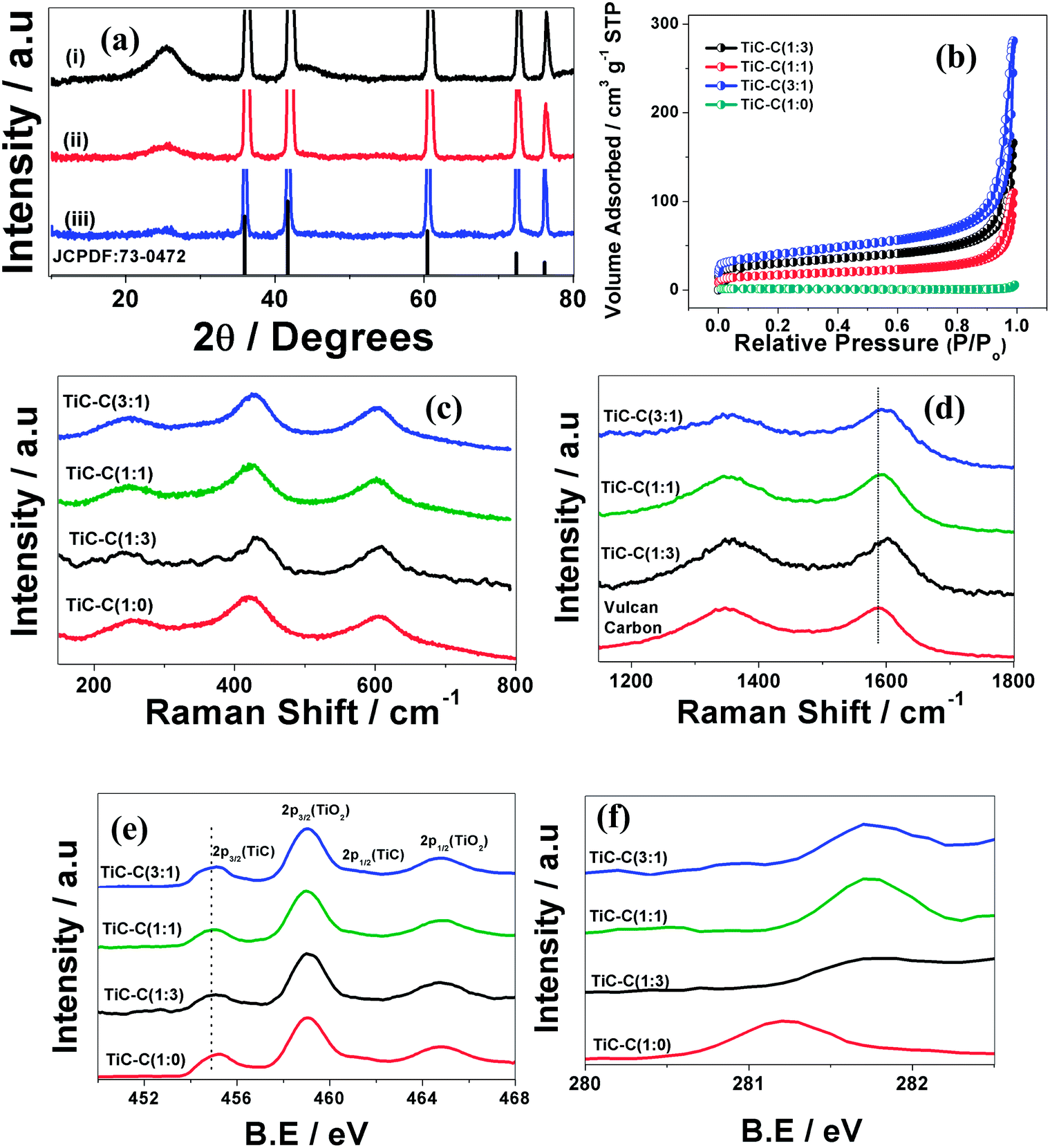 | ||
| Fig. 1 (a) X-ray diffraction patterns of (i) TiC–C (1:3) (ii) TiC–C (1:1), (iii) TiC–C (3:1). (b) shows BET isotherms of TiC–C composites. (c and d) and (e and f) represent Raman spectra and XPS spectral regions of Ti-2p, C-1s, respectively. | ||
The catalysts are further characterized using BET measurements [Fig. 1(b)]. Prior to the measurements, all the catalysts are pre-treated at 120 °C for 4 h. The surface area of bare TiC particles is found out to be 3.1 m2 g−1 where as the composites exhibit surface areas of 103 (1:1 composition of TiC:C), 139 (1:3) and 58 (3:1) m2 g−1. A decrease in surface area is observed with increase in TiC content. The surface area differences may affect the diffusion characteristics since the porosity may be different.
The resistivity values for all the composites are measured using two probe method. A known amount of catalyst is dispersed in ethanol and vacuum filtered using Whatman membranes with the help of Millipore vacuum filtration unit. The films are well-dried and during this process little cracks are observed especially in the case of composites. Uniform films without any crack are obtained for TiC. Measurements are performed in the regions where there are no cracks, using Keithley meters. The resistivity value for TiC is found out to be 193 ohm cm while the resistivity decreases drastically in the case of composites ranging from 1.5 to 4.1 ohm cm, measured under identical conditions. TiC shows relatively poor lateral sheet conductivity. Though TiC is known to be highly conducting, the poor lateral conductivity might be due to large separation of individual particles in addition to the presence of TiO2 on the surface. Decrease in resistivity observed for the composites indicate that the particles are well interconnected leading to percolation-type conduction. Presence of carbon contributes to high conductivity.
Raman spectroscopic measurements are performed for TiC and TiC–C composites and the results are shown in Fig. 1(c and d). The spectra show bands located at 258, 419 and 605 cm−1 and are ascribed to the presence of surface defects, edge defects and disorder induced by carbon vacancies.21 Further, the presence of carbon is evidenced by the appearance of bands in the region, 1150–1850 cm−1. The composites show two peaks at 1348 cm−1 and 1595 cm−1 and the former band is due to the breathing modes of sp2 atoms in rings and the latter one is G-band, arising from C–C stretching of sp2 carbon atoms present in both rings and chains.41 Raman spectrum is recorded for Vulcan carbon for comparison. As shown in Fig. 1(d), there is a shift of around 7 cm−1 noted for G band in case of composites as compared to pristine carbon. The observed shift is due to charge transfer interactions between TiC and carbon. Similar shifts in G-band have been observed for graphene with various molecules and metal nanoparticles such as Pt, Ag, and Au.42,43 It has been earlier reported based on soft X-ray emission studies that there can be a charge transfer across TiC and amorphous carbon interface.44 It is noteworthy that charge transfer interactions between TiC and carbon are observed in the present studies though particle sizes are very different from that of the above mentioned reference.
The surface oxidation states of the samples are analyzed using XPS. Fig. 1(e and f) represents deconvoluted regions corresponding to Ti-2p and C-1s spectra for TiC and TiC–C composites. The presence of peaks located at binding energy values (B.E) around 455 eV and 461 eV corresponds to Ti–C linkages.17,20,21 The spectra also reveal another pair of peaks situated at 459 eV and 464.5 eV, due to TiO2 phase.17,20,21 As shown in Fig. 1(f), C-1s spectra consist of peak around 281 eV, confirming the presence of TiC20,21 in all samples. On close examination of the peaks corresponding to TiC, a slight shift to low B.E values (∼0.2–0.3 eV) is found, indicating weak charge transfer interactions between TiC and carbon. However, one needs to be very cautious as the shifts are very small. The shifts are more prominent in C-1s region of all the samples. The interfacial surface areas between TiC and carbon possibly contribute to a difference in catalytic activity. Similar effects have earlier been observed when Pt is deposited on titanium nitride particles.9
As shown in Fig. 2(a), TiC–C (1:1) composite contains two phases with clear contrast difference and is attributed to the presence of TiC and carbon which is evident from EDS pattern [Fig. 2(b)]. The polydisperse, commercial TiC (bright regions) particles are dispersed well with carbon particles (dark regions). The EDS mapping shows the presence of various constituents in the composites [Fig. 3(a)–(c)]. The data reveal the existence of Ti and C, extracted from Ti-mapping and C-mapping. Similar observations have been found in the case of all composites. The composites are further characterized using TEM. Fig. 4 represents TEM image of TiC–C composite. High resolution TEM indicates that TiC particles are crystalline in nature and fast Fourier transform (FFT) pattern of the selected region shows diffraction spots that correspond to fcc phase of TiC. To differentiate TiC and carbon, scanning TEM (STEM) images are recorded. The data shown in Fig. S2† represents STEM bright field and dark field images of a particular region. Since the images are Z-contrast images, we can clearly say from DF image that the regions appear bright represent TiC as Ti possess high atomic number than C. To further confirm this, elemental maps are recorded from the region shown in Fig. S3,† which again confirms the presence of Ti and carbon, corroborating SEM data.
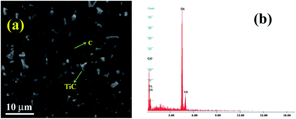 | ||
| Fig. 2 (a) SEM image of TiC–C (1:1) composite and (b) corresponding EDS pattern. | ||
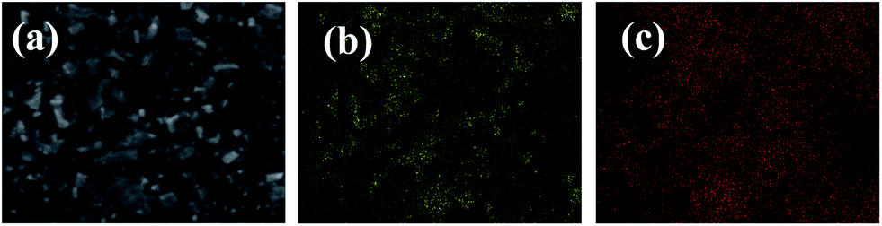 | ||
| Fig. 3 (a) SEM image and corresponding elemental maps of (b) titanium and (c) carbon for TiC–C (1:1) composite. | ||
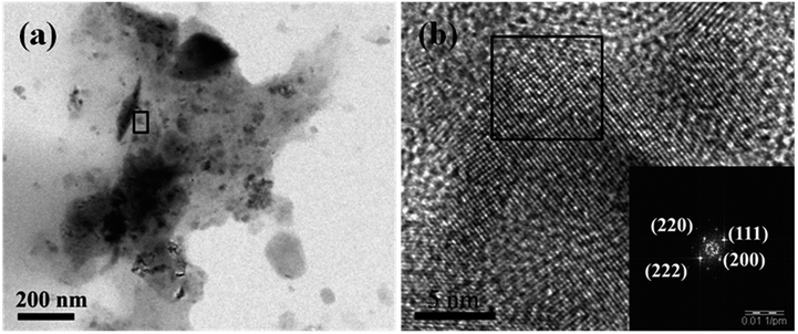 | ||
| Fig. 4 (a) TEM image of TiC–C (1:1) composite and (b) represents high resolution TEM of the region marked in (a). Inset of (b) shows FFT of the region marked in (b). | ||
ORR studies
Electrochemical reduction of oxygen has been investigated using TiC and all the three composites, namely TiC–C (1:1, 1:3 and 3:1, by weight). Cyclic voltammetric studies indicate superior activity of the composite catalysts towards ORR. As indicated in Fig. S4(a)–(d),† the appearance of a broad peak between −0.1 and −0.5 V vs. MMO on potential excursion towards negative values is attributed to oxygen reduction, which is absent in the case of N2-saturated electrolytes. Similar peak potentials for ORR have been reported by several groups on carbon-based materials in alkaline media.45–47 The peak potential as well as onset potential for ORR are different for different materials studied (Fig. 5), and are more positive in the case of TiC–C (1:1) where the peak potential is around −0.3 V vs. MMO. The TiC–C (1:1) composite seems to be the best amongst the investigated catalysts [Fig. 5].
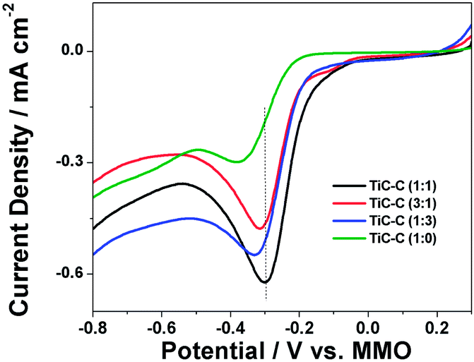 | ||
| Fig. 5 Cyclic voltammograms for ORR obtained using bare TiC and TiC–C composites. Supporting electrolyte used is 0.5 M KOH and scan rate used is 0.05 V s−1. Details of the samples are given in the figure. | ||
Rotating disk electrode (RDE) measurements are performed in linear potential scan mode at a scan rate of 0.005 V s−1. This study gives precise information about kinetic parameters. Fig. S5(a–d) (ESI†) shows the effect of rotation rate on i–v behaviour of ORR. The currents increase as a function of rotation rate owing to the availability of high reactant flux at the working electrode at high rotation rates. The absence of well-defined limiting current plateau is attributed to the presence of residual contribution from mixed kinetic and diffusion control processes as reported in the literature.48,49 As compared with bare TiC [Fig. 6(a)], TiC–C composites show positive shift in the onset potential with more pronounced increase in current density. Further, the activity of TiC towards ORR strongly depends on the amount of carbon present in the composite and TiC–C (1:1) is found to be the optimum composition for obtaining the best activity.
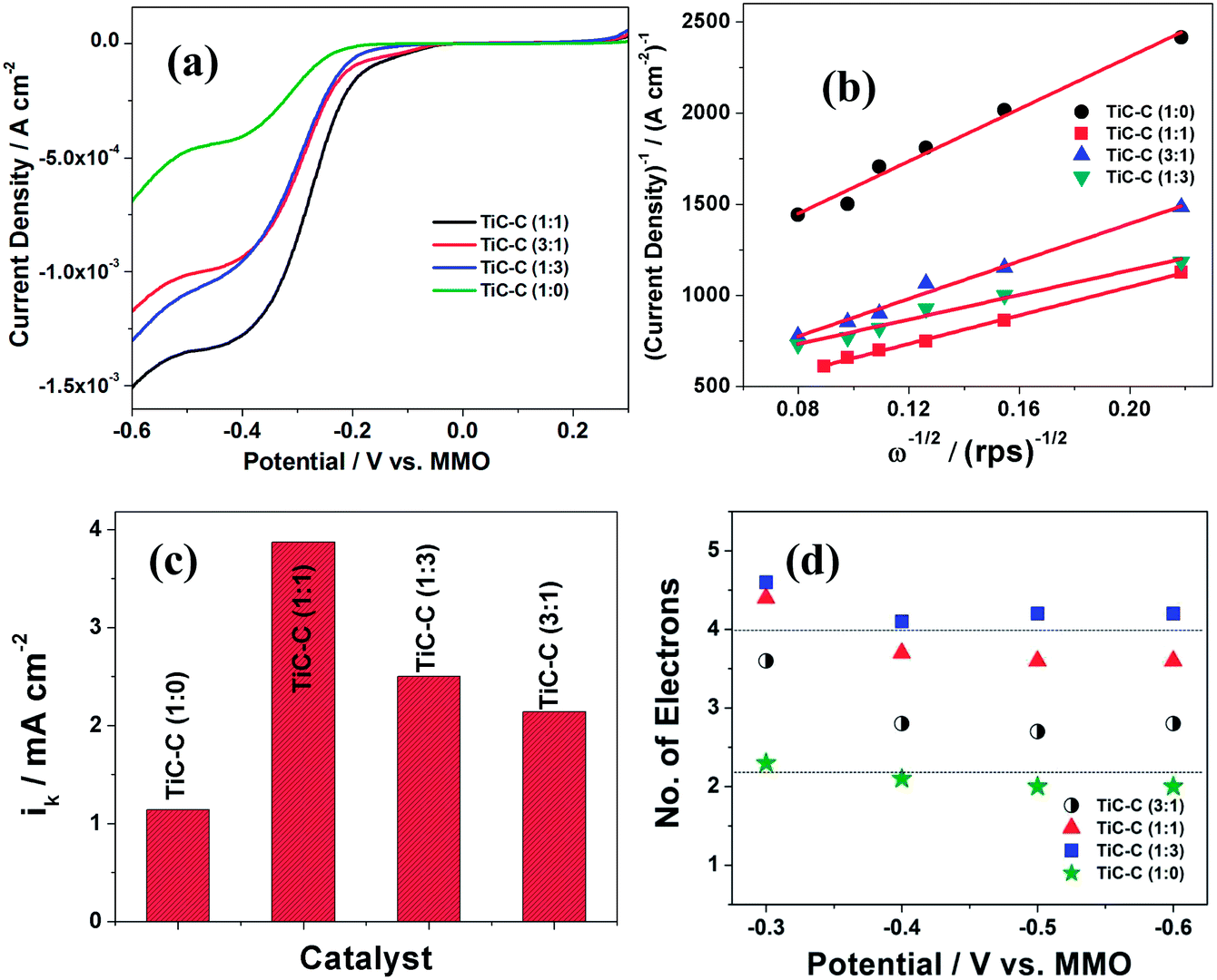 | ||
| Fig. 6 (a) Linear sweep voltammograms for ORR in 0.5 M KOH at 1000 rpm and at a scan rate 0.005 V s−1 on various catalysts. (b) K–L plots obtained at a DC bias value of −0.6 V. (c) represents variation of ik with catalyst obtained at −0.6 V and (d) represents number of electrons as a function of potential obtained on various catalysts in O2-saturated 0.5 M KOH electrolyte. Details of the catalysts are given in figure. | ||
As shown in Fig. S6,† the linear plots are not passing through origin and suggest possible deviations. Thus, Koutecky–Levich equation is used to analyze the data. Apparent kinetic parameters are extracted by treating the data shown in Fig. 6(b) and S5† based on Koutecky–Levich methodology (eqn (3)). The data depict the dependence of 1/i with 1/ω at various potentials. It is possible to determine the number of electrons (n) from the slope and kinetic current density (ik) from the intercept as given in eqn (4).
| 1/i = 1/ik + 1/id | (3) |
| 1/i = −1/(nFkCo) − 1/(0.62 nFDo2/3ν−1/6Coω1/2) | (4) |
500 C mol−1), k is rate constant for ORR, Do is diffusion coefficient (1.65 × 10⁻⁵ cm2 s−1),50 Co is bulk concentration of O2 (0.84 × 10⁻⁶ mol cm−3),50 ν is kinematic viscosity (0.01 cm2 s−1)50 and ω is rotation speed of electrode (revolutions per s).
Fig. S6† represents K–L plots obtained on various catalysts at different potentials. By equating experimentally obtained slope (Fig. S6†) with the theoretical expected slope (eqn (4)) along with substitution of corresponding parameters, n value can be calculated. The value of n is around 3.5–4 in case of TiC–C composites depending on the composition whereas it is around 2 with bare TiC [Fig. 6(d)]. This suggests that four electron, direct conversion of O2 to H2O can be realized on composites unlike bare TiC and pristine Vulcan XC72R carbon, where it is a two electron process in alkaline media.21,51 Thus, it is obvious that composites give better efficiency for ORR than that of the bare TiC. Similarly, the values of ik at −0.6 V can be extracted from the intercepts as given in Fig. 6(b) and the results are shown in Fig. 6(c). The catalysts with composition 1:1 have best efficacy towards ORR as compared to other compositions and is in line with other voltammetric findings given earlier. The obtained ik values are comparable with reported values on W2C/C11 ruthenium tetrakis (diaquaplatinum)octacarboxy phthalocyanine modified MWCNT,52 gold nanoclusters,53 3 nm gold clusters (3.5 mA cm−2, at −0.6 V vs. Ag/AgCl) and 7 nm gold clusters (1.5 mA cm−2 at −0.6 V vs. Ag/AgCl).54 The present studies have used geometric areas for determining the apparent kinetic parameters since we are unable to obtain the electrochemically active area of TiC. It should be pointed out that the studies carried out using different loadings of the catalysts on the same glassy carbon electrode of diameter 0.3 cm, reveals the number of electrons to be the same for all the catalysts studied.
One of the major hurdles in fuel cell community is the cross-over of fuel from anode to cathode compartment. In order to overcome this, highly methanol tolerant cathode catalysts are greatly in demand for achieving good efficiencies. To address this issue, ORR studies are performed in presence of methanol. Chronoamperometric studies are performed by holding the electrode at a potential −0.25 V vs. MMO with successive addition of different concentrations of methanol. For comparison, similar measurements are carried out with commercial 40 wt% Pt/C catalyst. As shown in Fig. 7(a), the amperometric response from bare TiC and TiC–C composites remains unaltered even after the addition of methanol. But in case of 40 wt% Pt/C, a sharp decrease in current is noted upon the addition of methanol. This result again confirms the advantage of high methanol tolerance in case of TiC and TiC–C composites over commercial Pt/C. To understand durability of the catalyst, cyclic voltammograms are recorded over 700 cycles and it is observed that very stable performance is shown up to 700 cycles. The normalized peak current with respect to first cycle is shown in Fig. 7(b). Stable performance of ORR with retention of 80% of initial current density is observed.
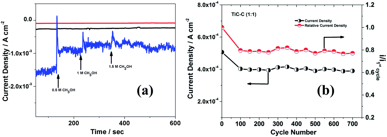 | ||
| Fig. 7 (a) i–t transients for ORR on bare TiC (red), TiC–C (1:1) (black)and 40 wt% Pt/C (blue) in O2-saturated 0.5 M KOH at DC bias of −0.25 V vs. MMO with successive additions of different concentrations of methanol. Loading of Pt used is 57 μg cm−2. (b) Peak current density as a function of cycle number for ORR on TiC–C (1:1) in O2-saturated 0.5 M KOH. Scan rate used is 0.05 V s−1. Normalized currents with respect to first cycle are also shown in (b). | ||
Studies on borohydride oxidation
Voltammograms are recorded for borohydride oxidation using varying ratios of TiC–C composites. As shown in the Fig. S7,† there is a clear indication of the oxidation of borohydride based on the commencement of peaks in the presence of borohydride and which are absent in the absence of borohydride. Further, the peaks correspond to borohydride oxidation increase with increasing the concentration of borohydride, strongly confirms the oxidation of borohydride. As reported in our earlier study,20 the forward peak is assigned to the direct oxidation of borohydride (eqn (1)) while the peak in the reverse direction is likely to be due to the oxidation of intermediates (possibly BH3OH−) that are formed during the forward scan. As shown in Fig. 8(a), there is a clear dependence of composition on electroactivity of borohydride oxidation recorded under identical conditions. The appearance of peaks in the forward as well as reverse directions is similar to that reported for other electrode materials.20,37,38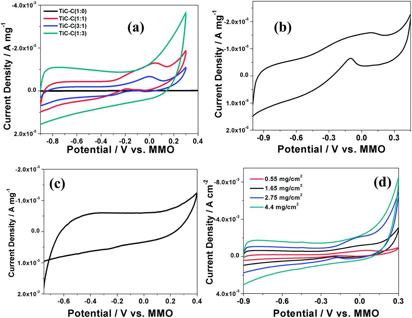 | ||
| Fig. 8 (a) Cyclic voltammograms of borohydride oxidation on bare TiC and TiC–C composites coated onto GC electrode; (b) shows voltammogram correspond to bare TiC. (c) shows voltammogram that corresponds to bare carbon electrode. (d) Cyclic voltammograms of borohydride oxidation showing effect of loading of TiC–C (1:1) for 0.1 M NaBH4 in 1 M NaOH is the electrolyte used at a scan rate of 0.05 V s−1. | ||
Among the composites studied, TiC (1:1) is found to be superior to others. The voltammograms recorded using TiC–C (1:3) does not show any peak for borohydride oxidation. However, an increase in currents observed in the presence of borohydride is also indicative of high capacitive currents due to carbon that actually mask borohydride oxidation currents. Effect of loading of TiC–C (1:1) on borohydride oxidation is studied and the results are depicted in Fig. 8(d). Increase in peak current is observed with increasing loading of the catalyst. However, beyond a certain threshold, the performance decreases. This could be due to blocking of catalytic sites at high loadings as reported earlier for Ni-based composites.55 A thick catalyst layer increases the resistance and reduces mass transport of reactants to catalytic sites.55 Further, peak currents are monitored as a function of concentration of borohydride and the peak currents vary linearly with concentration of borohydride. The oxidation process is diffusion limited as the peak currents vary linearly with square root of scan rate (data not shown).
Based on the above observations, it is clear that TiC can be used as a non-Pt catalyst for ORR and borohydride oxidation. The improved activities observed in the case of TiC–C composites may be due to the following reasons. It seems to be a synergism which is active because of the presence of carbon, playing a vital role in dictating electroactivity. Enhanced activities for ORR are reported using carbon supported catalysts both theoretically and experimentally. It is important to mention that availability of large number of electrode–electrolyte–gas three-phase boundaries (TPB) is mandatory for efficient electron transfer. Thus, in the case of bare TiC (low conductivity), active sites are limited to narrow regions of TPB boundaries because of poor electron transfer efficiency leading to inefficient activity. In the case of TiC–C composites, the active sites can spread over the entire surface of the catalyst due to availability of wider TPB zones (due to high conductivity), which in turn facilitates good activity towards ORR and borohydride oxidation. Qiao et al. reported similar observations with experimental as well as theoretical studies using graphitic-carbon nitride (g-C3N4) catalyst for ORR.56 We believe that the interfacial charge transfer as evidenced from Raman and XPS study may be one of the crucial factors which results in the observed activities. Thus, the presence of carbon plays a multi-role, one in improving electronic conductivity, secondly in increasing the availability of wide TPB zones and thirdly in providing a charge transfer at the interface between TiC and carbon.
Conclusions
Multi-functional electrochemical aspects of titanium carbide have been demonstrated using oxygen and borohydride as probe molecules. The composites of TiC with Vulcan XC72R carbon display improved catalytic activities for ORR and borohydride oxidation. Among composites studied, TiC–C (1:1) is proved to be a superior catalyst as compared to other investigated materials. Further, the present catalysts can reduce oxygen quite effectively with high degree of specificity in presence of methanol. Also, these catalysts can be used for long term applications owing to the robustness of TiC, a corrosion resistant material. Thus, the present study opens up a way to assemble a DBFC architecture which is completely Pt-free.
Notes and references
- R. Borup, J. Meyers, B. Pivovar, Y. S. Kim, R. Mukundan, N. Garland, D. Myers, M. Wilson, F. Garzon, D. Wood, P. Zelenay, K. More, K. Stroh, T. Zawodzinski, J. Boncella, J. E. McGrath, M. Inaba, K. Miyatake, M. Hori, K. Ota, Z. Ogumi, S. Miyata, A. Nishikata, Z. Siroma, Y. Uchimoto, K. Yasuda, K. I. Kimijima and N. Iwashita, Chem. Rev., 2007, 107, 3904 CrossRef CAS PubMed.
- W. Xiong, F. Du, Y. Liu, A. Perez, M. Supp, T. S. Ramakrishnan, L. M. Dai and L. Jiang, J. Am. Chem. Soc., 2010, 132, 15839 CrossRef CAS PubMed.
- M. K. Debe, Nature, 2012, 486, 43 CrossRef CAS PubMed.
- L. E. Toth, Transition Metal Carbides and Nitrides, Academic Press, New York, NY, USA, 1971 Search PubMed.
- Z. G. Liu, J. T. Guo, L. L. Ye, G. S. Li and Z. Q. Hu, Appl. Phys. Lett., 1994, 65, 2666 CrossRef CAS PubMed.
- M. S. El-Eskandarany, J. Alloys Compd., 2000, 305, 225 CrossRef CAS.
- M. Wu, X. Lin, Y. Wang, L. Wang, W. Guo, D. Qi, X. Peng, A. Hagfeldt, M. Grätzel and T. Ma, J. Am. Chem. Soc., 2012, 134, 3419 CrossRef CAS PubMed.
- M. M. O. Thotiyl, T. Ravi Kumar and S. Sampath, J. Phys. Chem. C, 2010, 114, 17934 CAS.
- M. M. O. Thotiyl, T. Ravi Kumar and S. Sampath, J. Mater. Chem., 2010, 20, 10643 RSC.
- M. M. O. Thotiyl and S. Sampath, Electrochim. Acta, 2011, 56, 3549 CrossRef CAS PubMed.
- H. Meng and P. K. Shen, Electrochem. Commun., 2006, 8, 588 CrossRef CAS PubMed.
- Z. Hu, C. Chn, H. Meng, R. Wang, P. K. Shen and H. Fu, Electrochem. Commun., 2011, 13, 763 CrossRef CAS PubMed.
- M. Pang, C. Li, L. Ding, J. Zhang, D. Su, W. Li and C. Liang, Ind. Eng. Chem. Res., 2010, 49, 4169 CrossRef CAS.
- V. Presser, M. Heon and Y. Gogotsi, Adv. Funct. Mater., 2011, 21, 810 CrossRef CAS.
- P. Patel, I.-S. Kim and P. N. Kumta, J. Mater. Sci. Eng. B, 2005, 116, 347 CrossRef PubMed.
- A. Gringoz, N. Glandut and S. Valette, Electrochem. Commun., 2009, 11, 2044 CrossRef CAS PubMed.
- B. Bas, R. Piech, E. Niewiara, M. Ziemnicka, L. Stobierski and W. W. Kubiak, Electroanalysis, 2008, 20, 1655 CrossRef CAS.
- A. Ignaszak, C. Song, W. Zhu, J. Zhang, A. Bauer, R. Baker, V. Neburchilov, S. Ye and S. Campbell, Electrochim. Acta, 2012, 69, 397 CrossRef CAS PubMed.
- L. Hu, K. Huo, R. Chen, X. Zhang, J. Fu and P. K. Chu, Chem. Commun., 2010, 46, 6828 RSC.
- V. Kiran, S. B. Kalidindi, B. R. Jagirdar and S. Sampath, Electrochim. Acta, 2011, 56, 10493 CrossRef CAS PubMed.
- V. Kiran, K. Srinivasu and S. Sampath, Phys. Chem. Chem. Phys., 2013, 15, 8744 RSC.
- D. Eder, Chem. Rev., 2010, 110, 1348 CrossRef CAS PubMed.
- M. Baibarac and P. Gómez-Rom, J. Nanosci. Nanotechnol., 2006, 6, 289 CAS.
- R. V. Salvatierra, M. M. Oliveira and A. J. G. Zarbin, Chem. Mater., 2010, 22, 5222 CrossRef CAS.
- J. K. W. Sandler, J. E. Kirk, I. A. Kinloch, M. S. P. Shaffer and A. H. Windle, Polymer, 2003, 44, 5893 CrossRef CAS.
- Y. Li, H. Wang, L. Xie, Y. Liang, G. Hong and H. Dai, J. Am. Chem. Soc., 2011, 133, 7296 CrossRef CAS PubMed.
- F. Li, R. Ohnishi, Y. Yamad, J. Kubot, K. Domen, A. Yamad and H. Zhou, Chem. Commun., 2013, 49, 1175 RSC.
- E. Ramasamy, C. Jo, A. Anthonysamy, I. Jeong, J. K. Kim and J. Lee, Chem. Mater., 2012, 24, 1575 CrossRef CAS.
- Y. Qiu, K. Yan, S. Yang, L. Jin, H. Deng and W. Li, ACS Nano, 2010, 4, 6515 CrossRef CAS PubMed.
- G. R. Li, F. Wang, J. Song, F. Y. Xiong and X. P. Gao, Electrochim. Acta, 2012, 65, 216 CrossRef CAS PubMed.
- C. Celik, F. G. B. San and H. I. Sarac, J. Power Sources, 2008, 185, 197 CrossRef CAS PubMed.
- U. B. Demirci, J. Power Sources, 2007, 172, 676 CrossRef CAS PubMed.
- V. Kiran and S. Sampath, J. Indian Inst. Sci., 2009, 89, 447 CAS.
- E. Fakioglu, Y. Yurum and T. N. Veziroglu, Int. J. Hydrogen Energy, 2004, 29, 1371 CrossRef CAS PubMed.
- M. H. Atwan, D. O. Northwood and E. L. Gyenge, Int. J. Hydrogen Energy, 2007, 32, 3116–3125 CrossRef CAS PubMed.
- M. H. Atwan, C. L. B. Macdonald, D. O. Northwood and E. L. Gyenge, J. Power Sources, 2006, 158, 36 CrossRef CAS PubMed.
- E. L. Gyenge, M. Atwan and D. O. Northwood, J. Electrochem. Soc., 2006, 153, A150 CrossRef CAS PubMed.
- V. Kiran, T. Ravikumar, N. T. Kalyanasundaram, S. Krishnamurty, A. K. Shukla and S. Sampath, J. Electrochem. Soc., 2010, 157, B1201 CrossRef CAS PubMed.
- V. W. S. Lam and E. L. Gyenge, J. Electrochem. Soc., 2008, 155, B1155 CrossRef CAS PubMed.
- M. Simoes, S. Baranton and C. Countanceau, J. Phys. Chem. C, 2009, 113, 13369 CAS.
- A. C. Ferrari, Solid State Commun., 2007, 143, 47 CrossRef CAS PubMed.
- K. S. Subrahmanyam, A. K. Manna, S. K. Pati and C. N. R. Rao, Chem. Phys. Lett., 2010, 497, 70 CrossRef CAS PubMed.
- C. N. R. Rao and R. Voggu, Mater. Today, 2010, 13, 34 CrossRef CAS.
- M. Magnuson, E. Lewin, L. Hultman and U. Jansson, Phys. Rev. B: Condens. Matter Mater. Phys., 2009, 80, 235108 CrossRef.
- S. Wang, D. Yu, L. Dai, D. W. Chang and J. B. Baek, ACS Nano, 2011, 5, 6202 CrossRef CAS PubMed.
- S. Wang, D. Yu and L. Dai, J. Am. Chem. Soc., 2011, 133, 5182 CrossRef CAS PubMed.
- S. Wang, E. Iyyamperumal, A. Roy, Y. Xue, D. Yu and L. Dai, Angew. Chem., Int. Ed., 2011, 50, 11756 CrossRef CAS PubMed.
- A. Sarapuu, N. Nurmik, H. Mandar, A. Rosental, T. Laaksonen, K. Kontturi, D. J. Schiffrin and K. Tammeveski, J. Electroanal. Chem., 2008, 612, 78 CrossRef CAS PubMed.
- V. S. Dilimon, N. S. Venkata Narayanan and S. Sampath, Electrochim. Acta, 2010, 55, 5930 CrossRef CAS PubMed.
- I. Kruusenberg, N. Alexeyeva and K. Tammeveski, Carbon, 2009, 47, 651 CrossRef CAS PubMed.
- J. Guo, A. Hsu, D. Chu and R. Chen, J. Phys. Chem. C, 2010, 114, 4324 CAS.
- N. W. Maxakato, S. A. Mamuru and K. I. Ozoemena, Electroanalysis, 2011, 23, 325 CrossRef CAS.
- W. Chen and S. Chen, Angew. Chem., Int. Ed., 2009, 48, 4386 CrossRef CAS PubMed.
- W. Tang, H. Lin, A. K. Shwarsctein, G. D. Stucky and E. W. McFarland, J. Phys. Chem. C, 2008, 112, 10515 CAS.
- J. Ma, Y. Sahai and R. G. Buchheit, J. Power Sources, 2010, 195, 4709 CrossRef CAS PubMed.
- Y. Zheng, Y. Jiao, J. Chen, J. Liu, J. Liang, A. Du, W. Zhang, Z. Zhu, S. C. Smith, M. Jaroniec, G. Q. Lu and S. Z. Qiao, J. Am. Chem. Soc., 2011, 133, 20116 CrossRef CAS PubMed.
Footnote |
| † Electronic supplementary information (ESI) available: (S1) estimation of titanium, (S2) voltammograms of ORR on TiC and TiC–C composites, (S3) LSV showing effect of rotation speed on ORR for TiC and TiC–C composites, (S4) K–L plots obtained using TiC and TiC–C composites. See DOI: 10.1039/c3ra46281a |
| This journal is © The Royal Society of Chemistry 2014 |