Self-regenerative adsorbent based on the cross-linking chitosan for adsorbing and mineralizing azo dye

Fei Yu ab, Lu Chenac, Jie Ma*a, Yiran Suna, Qiang Lia, Chenlu Lia, Mingxuan Yanga and Junhong Chen*d
aState Key Laboratory of Pollution Control and Resource Reuse, School of Environmental Science and Engineering, Tongji University, 1239 Siping Road, Shanghai 200092, China. E-mail: jma@tongji.edu.cn; Fax: +86 21 65981831; Tel: +86 21 65981831
bSchool of Chemical and Environmental Engineering, Shanghai Institute of Technology, 100 Hai Quan Road, Shanghai 201418, China. E-mail: fyu@vip.163.com
cDepartment of Civil and Environmental Engineering, University of Michigan, 2350 Hayward Street, Ann Arbor, USA
dDepartment of Mechanical Engineering, University of Wisconsin–Milwaukee, Milwaukee, WI 53211, USA. E-mail: jhchen@uwm.edu

Received 22nd October 2013 , Accepted 16th December 2013

First published on 18th December 2013


Abstract

In this work, we synthesized self-regenerative chitosan (SRCS) by combining the photo-catalyst TiO2 and cross-linking chitosan (CS). The novel SRCS hybrids were then used as adsorbents to remove methyl orange (MO) and they demonstrated excellent adsorption capacity (∼799.2 mg g−1) and significant photocatalytic self-regenerative properties. The pseudo-first-order (PFO), pseudo-second-order (PSO) and Weber–Morris kinetics models were applied to fit the experimental data obtained from batch experiments. The PSO kinetic model was more appropriate for describing the adsorption of MO onto the SRCS. Interestingly, the SRCS adsorbent was successfully regenerated by UV photocatalysis after adsorption. More importantly, the adsorption effectiveness of the SRCS remained constant through eight regeneration cycles. This study provides a green method of removing organic pollutants that combines adsorption enrichment with photocatalytic degradation.
1. Introduction

Among the operations involved in water and wastewater treatment, adsorption occupies an important position.1–3 As adsorbents have a finite capacity for pollutant molecules, it is necessary either to regenerate or dispose of them. With the increasingly widespread use of adsorbents in water treatment, disposable adsorbents are not only a waste of resources but also pose a significant danger to the environment themselves, so the disposal of adsorbents as waste is not an economic option. Thus, finding ways to regenerate adsorbents efficiently is a practical problem yet to be solved. Eco-friendly regeneration would improve the living environment as well as bring great economic benefits. Traditional adsorbent regeneration methods simply restore their activity and recover most of their adsorbability. An ideal regeneration process also requires the elimination of pollutants so that they do not diffuse into the environment, thus avoiding secondary pollution.

At present, regeneration methods can be divided into two categories: wet reclamation and dry reclamation. Dry reclamation includes thermal regeneration,4,5 microwave regeneration,6,7 etc. Thermal regeneration is the most popular and natural method used in the industry.4 However, thermal regeneration might cause incomplete combustion, and any newly generated gas needs to be treated. Because of the residue and ineffective regeneration issues, research has focused on combined treatments to avoid the shortcomings of thermal regeneration.8,9 In recent years, microwave irradiation has been proposed as a potentially viable tool for regeneration due to its ability to effect homogeneous and instantaneous heating.10 Microwave-assisted regeneration offers advantages over conventional treatments including rapid and precise temperature control, small space requirements, energy savings, and greater efficiency during intermittent use.11,12 But it still presents the problems that some organics might volatilize but not mineralize and it cannot be used for continuous regeneration, which leads to complex operations.

Wet reclamation includes biological regeneration,13 solvent regeneration,14 and electrochemical regeneration.15,16 Solvent regeneration can recover useful substances from the regeneration liquid, and the technical process is easy to implement in practical production processes.17 However, using this method, regeneration is not complete due to the fact that the pores in the activated carbon can easily become air-logged, affecting the recovery rate.18 Different acids have been used to remove heavy metal ions; however, after regeneration the wastewater still contains heavy metal ions and needs further treatment. Özgür19 reviewed the bioregeneration method and pointed out it may decrease the costs of regeneration and replacement of activated carbon by extending the life-time of powdered/granular activated carbon. The biological method is simple and economical but susceptible to temperature variations and other external factors. Han et al.20 showed that the regeneration efficiency remains over 70% after 10 cycles using electrochemical regeneration. The integrative electrosorption regeneration cycle process can simplify the regeneration procedure and also decrease the adsorption costs. But this method also attracts high electricity and maintenance costs.

In recent years, organic dye pollutants from various chemical and textile industries have received much attention because of the environmental risks they pose, which not only include aesthetic problems but also high biotoxicity and potential mutagenic and carcinogenic effects.21,22 Therefore, the removal of dyes is currently of high importance for environmental remediation. Chitosan (CS) is the most abundant biopolymer in nature after cellulose, and is easily prepared from chitin by deacetylating its acetoamide groups in a strong alkaline solution. The large numbers of amino groups in CS have been found to provide novel adsorption sites for many metal ions23,24 and organic dyes.25,26 The regeneration of CS usually depends on desorption of alkali and acids, such as NaOH,27 NaHCO3,28 and HCl.29 Although these methods can regenerate CS quickly and effectively, they still cause secondary pollution. The above methods also have some general disadvantages such as heat loss leading to thermal inefficiency, the requirement of very low operating pressure, and effectiveness only for weakly adsorbed species.

In this paper, we synthesized self-regenerative CS (SRCS) by combining the photocatalyst TiO2 and cross-linking CS. The resulting SRCS hybrids exhibit excellent adsorption and photocatalytic self-regenerative properties. The novel SRCS hybrids were thus used as adsorbents to remove a dye from aqueous solutions. Methyl orange (MO) is a well-known anionic dye, which is widely used in the textile and printing industries and in research laboratories. Hence, MO was selected as a representative target pollutant in this study. After adsorption, the SRCS adsorbent was successfully regenerated by UV photocatalysis. The regeneration life-time experiments indicate that the adsorption effectiveness of the SRCS does not significantly change between the first cycle and the eighth cycle. Photocatalysis not only changes the chemical adsorption equilibrium, shifting the adsorption reaction towards the favorable direction of adsorption, but also regenerates the adsorbent and mineralizes the dye. This study provides a green method that combines adsorption enrichment with self-photocatalysis degradation for MO removal.

2. Experimental methods

2.1. Materials and chemicals

All chemicals were of analytical purity and purchased from Sinopharm Chemical Reagent Co., Ltd (Shanghai, China) and used in the experiments directly without any further purification. All solutions were prepared using deionized water. Titanium dioxide powder (P25, 20% rutile and 80% anatase) was purchased from Degussa.

2.2. Preparation of SRCS

CS (3 g) and P25 (2 g) nanoparticles were added to 100 mL of acetic acid (2 vol%) with continuous stirring for 10 min, and then sodium hydrogen carbonate (0.6 g) was added with rigorous stirring. Then 25 mL formaldehyde were added to the above solution with continuous stirring for 30 min at room temperature. The CS composite was filtered and washed with distilled water. A solution of 2 mL epichlorohydrin and 200 mL sodium hydroxide (0.8 mg) was prepared (pH = 10). Freshly prepared wet CS composite was added to this epichlorohydrin solution and the mixture was heated to 343 K for 2 h and stirred continuously. After 2 h the CS composite was filtered and washed repeatedly with distilled water to remove any unreacted epichlorohydrin and freeze-dried.

2.3. Regeneration studies

After adsorption, CS/TiO2 adsorbents were placed in a quartz pot in a black box under UV light. The regeneration reaction was complete after 30 min, the samples were rinsed with distilled water, and then the samples were dehydrated by freeze-drying. The adsorption experiments of the obtained samples were conducted as the first regeneration cycle adsorbent. The above process was repeated 7 times to study the ability of the photocatalytic technology to regenerate the adsorbents.

3. Results and discussion

An optical image of SRCS is shown in Fig. S1. The surface morphology of the SRCS was studied by SEM. The SEM of SRCS looks like a flower petal, and there are many macropores on the surface, as shown in Fig. 1a. The TiO2 particles are located on the surface of CS, as shown in Fig. 1b, which would improve the photocatalytic properties of MO during the regeneration process. Therefore, the adsorbent morphology can be expected to produce optimum photocatalytic performance.
image file: c3ra46035e-f1.tif
Fig. 1 SEM (a and b) and TG and DTA curve (c) of SRCS particles and XRD patterns (d) of P25, CS and SRCS particles.

The TG and DTA curves were shown in Fig. 1c, assuming that all CS materials have been oxidized, the amount of TiO2 in the sample can be estimated (40 wt%). XRD analysis was carried out to confirm the SRCS polymorphs and their crystalline phases. The peaks of SRCS corresponding to the mixture of the anatase and rutile phases, respectively, are shown in Fig. 1d. However, the existence of the rutile phase may be detrimental to the photoactivity as rutile has been reported to be associated with a fast recombination rate of generated electrons and holes. As observed in Fig. 1d, the major phase of TiO2 was predominantly anatase matching the standard JCPDS value (JCPDS no. 78-1285 and 86). The peak intensities of SRCS decreased after the addition of CS, and no new peaks appeared, which indicated the TiO2 phase does not change. This illustrated that TiO2 was successfully embedded in the SRCS particles. The average crystallite sizes of TiO2 and SRCS were calculated by Scherrer's equation using the full width at half maximum (FWHM) of the XRD peaks at 2θ = 25.3°, corresponding to the most intense anatase peak. The results reveal that typical values of anatase crystallite sizes as calculated using Scherrer's equation were ∼20.3 nm for P25 and ∼14.6 nm for SRCS. The average anatase crystallite size of TiO2 decreased with the addition of CS, which indicates the addition of CS can contribute to the dispersion of TiO2.

Fig. 2a shows the equilibrium isotherms for adsorption of MO dye onto SRCS, and the equilibrium adsorption characteristics were analyzed using the Langmuir30 and Freundlich31 isotherm models. Table S1 summarizes the determination coefficients (R2) of the Langmuir and Freundlich isotherms of SRCS. Based on those coefficients, the adsorption isotherm can be better described by the Langmuir model. The experimental results indicated that the computed maximum monolayer capacities of SRCS are ∼799.2 mg g−1. Furthermore, the isotherm shape was evaluated to predict whether an adsorption system is favorable or unfavorable. The RL value of SRCS adsorbents was 0.003 (initial MO concentration: 800 mg L−1), indicating that the adsorption of MO onto SRCS was favorable32 and that SRCS is an excellent adsorbent material for MO dye removal from aqueous solution. Dubinin–Radushkevich (D–R) isotherm model suggests that chemical adsorption is dominating in the adsorption process between the MO dye and SRCS adsorbent,33,34 as shown in Fig. S2.


image file: c3ra46035e-f2.tif
Fig. 2 Adsorption isotherms (t: 50 h, pH 7, 25 °C) and kinetic curves (pH 7, 25 °C) of MO on SRCS.

Adsorption is a physicochemical process that involves mass transfer of a solute from the liquid phase to the adsorbent surface. The transient behavior of the dye adsorption process was analyzed using different kinetic models. To study the adsorption kinetics of MO on SRCS, MO initial concentrations of 800 mg L−1 were used. The removal of MO by SRCS was found to be rapid during the initial period (in the first 1 h) and then became slower (1–5 h). However, MO desorbed from the SRCS (5–9 h) because it could easily enter and exit the macropores, which was confirmed by the SEM results. The rate of removal reached a plateau after approximately 48 h, as shown in Fig. 2b. Generally, the removal rate of pollutants is rapid initially but gradually decreases until it reaches equilibrium. This phenomenon is attributed to the fact that a large number of vacant adsorption sites are available for adsorption at the initial stage and, after a lapse of time, the remaining vacant adsorption sites are filled with difficulty due to repulsive forces between the solute molecules on the solid and in the bulk phase.35,36

In order to understand the characteristics of the adsorption process, the pseudo-first-order (PFO) and pseudo-second-order (PSO) kinetic models were applied to fit the experimental data obtained from batch experiments. The kinetic parameters and the determination coefficients were determined by nonlinear regression and are given in Table S2. The PSO kinetic model is more appropriate for describing the adsorption behavior of MO onto SRCS, as shown in Fig. S3b. Weber–Morris equation was applied to determine the actual rate-controlling step involved in the MO sorption process, the plots of qt against t1/2 are shown in Fig. S3c. The results suggested that intra-particle diffusion is not the rate-controlling step37 and that external mass transfer may also contribute significantly in the rate-controlling step due to the large intercepts of the linear portions of the plots,38 which also illustrated that there were many macropores on the SRCS surface. So the overall adsorption process may be jointly controlled by external mass transfer and intra-particle diffusion. The pH may be an important factor for the dye-binding capacity of SRCS because the amino groups of CS are more easily protonized in acid solution. To overcome this problem, some cross-linking agents are used to stabilize CS39,40 in acid solution and improve its mechanical properties.41

The pH may be an important factor for the dye-binding capacity of SRCS because the amino groups of CS are more easily protonized in acid solution. To overcome this problem, some cross-linking agents are used to stabilize CS39,40 in acid solution and improve its mechanical properties.41 Fig. 3 shows that higher adsorption capacities were found in the pH range 4–6, which could be explained by the fact that more protons were available to protonate the amine groups to form –NH3+ groups with positive charges because CS has a pKa value of 6.3–7.0, thereby enhancing the electrostatic attraction between the negatively charged dye anions and the positively charged surface of SRCS. The adsorption ability of SRCS decreased slowly as the pH rose; above pH 6, far fewer protonated amino groups were available for ionic interaction with the sulfonate groups of MO, leading to fewer dye molecules being adsorbed on SRCS. In addition, at pH values above 6, excessive hydroxyl ions might compete with the dye anions and, hence, obvious reductions in dye uptake were observed. Strong adsorption at a wide range of pH values proved that SRCS can be used conveniently in industrial applications.


image file: c3ra46035e-f3.tif
Fig. 3 Adsorption capacity of MO on SRCS at different pH values (MO concentration = 600 mg L−1, t: 50 h, 25 °C).

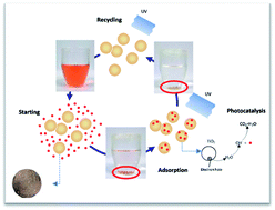
Adsorbent particles have a finite capacity for liquid phase molecules. It is necessary to regenerate the adsorbent. An appropriate method can decrease the cost and the complexity of management of the process. Finding a balance between economic considerations and the ecosystem becomes the decisive element in choosing an adsorbent. In this paper, excellent CS adsorbents loaded with TiO2 photocatalyst were obtained, so a new photocatalytic self-regeneration technology was introduced. In the photocatalytic self-regeneration process, the TiO2 catalyst in SRCS creates electron–hole pairs under UV light, which generates free radicals (hydroxyl radicals:˙OH) that mineralize MO and regenerate adsorbent molecules. The photocatalytic self-regeneration method does not require highly complex instruments or expensive chemical reagents. Fig. 4 shows the different stages of MO decolorization and adsorbent regeneration.


image file: c3ra46035e-f4.tif
Fig. 4 Schematic diagram of adsorption and photocatalytic regeneration of SRCS.

During the initial stage, the solution was orange and the particles were white, then the solution became colorless and the adsorbents (named SRCS-MO) became orange after adsorption. In the photocatalytic self-regeneration stage, the solution and adsorbents (named SRCS-R) both became colorless after 30 min after photocatalytic reaction, as shown in Fig. S4. And then, the chemical composition of the SRCS, SRCS-MO and SRCS-R adsorbents were further characterized by X-ray photoelectron spectroscopy (XPS), as shown in Fig. 5. Typical XPS survey scans and element analysis results of adsorbents are shown in Fig. 5a and Table S3, the presence of these sulphur chemical bonds demonstrates that MO adsorbed on the surface of SRCS. After photocatalytic self-regeneration, the quantity of sulphur and nitrogen elements decreased obviously, as shown in Fig. 5b and c. It suggests that the MO dye were photocatalytic degraded during photocatalytic self-regeneration process.


image file: c3ra46035e-f5.tif
Fig. 5 XPS survey scans (a), the S2p deconvolution (b), and the N1s deconvolution (c) of SRCS, SRCS-MO and SRCS-R.

This self-regeneration process can be recycled more than 8 times with no decrease in adsorption capacity. Fig. 6 shows the reuse behavior of the SRCS adsorbent upon MO sorption for an 8-cycle test. The saturated sorption capacity can be kept at ∼25 mg g−1 from the eighth cycle after regeneration with a UV lamp, indicating that the adsorption effectiveness of the SRCS adsorbent does not significantly change from the first cycle to the eighth cycle. More importantly, the MO dye has been photocatalytically degraded and mineralized, avoiding secondary pollution.


image file: c3ra46035e-f6.tif
Fig. 6 Regeneration ability of SRCS for MO adsorption (MO concentration = 20 mg L−1, t: 50 h, pH 7, 25 °C).

As is well known, the use of traditional adsorbents has some disadvantages, such as finite adsorption capacity, difficult regeneration recycling, and the transfer of pollutants from one place to another. In the SRCS adsorbents, TiO2 plays a role in degradation, and it also acts as a recycling agent. Photocatalysis not only changes the chemical adsorption equilibrium, pushing the adsorption equilibrium towards the direction of adsorption, but also regenerates adsorbent and mineralizes the dye. Compared to mere photocatalysis, adsorption by CS accelerates the degradation of MO and it also solves the problem of recovering TiO2 nanoparticles in solution.

4. Conclusion

In this work, we synthesized SRCS adsorbents by combining the photocatalyst TiO2 and cross-linking CS. The novel SRCS hybrids were used as adsorbents to remove MO from aqueous solutions. The resulting SRCS hybrids exhibit excellent adsorption and photocatalytic self-regeneration properties. The absorption effectiveness of the SRCS adsorbent does not obviously change after recycling 8 times. This study provides a green method that combines adsorption enrichment with photocatalytic degradation for removal of MO.

Acknowledgements

This research was supported by the National Natural Science Foundation of China (no. 21207100, 51072135) and Specialized Research Fund for the Doctoral Program of Higher Education (20120072120058). State Key Laboratory of Pollution Control and Resource Reuse Foundation (no. PCRRY11009, PCRRK09006)

References

  1. E. Katsou, S. Malamis, T. Kosanovic, K. Souma and K. J. Haralambous, Water, Air, Soil Pollut., 2012, 223, 5519–5534 CrossRef CAS.
  2. W. J. Shan, D. W. Fang, Z. Y. Zhao, Y. Shuang, L. Z. Ning, Z. Q. Xing and Y. Xiong, Biomass Bioenergy, 2012, 37, 289–297 CrossRef CAS PubMed.
  3. A. S. K. Kumar, S. Kalidhasan, V. Rajesh and N. Rajesh, Ind. Eng. Chem. Res., 2012, 51, 58–69 CrossRef CAS.
  4. S. W. Nahm, W. G. Shim, Y. K. Park and S. C. Kim, Chem. Eng. J., 2012, 210, 500–509 CrossRef CAS PubMed.
  5. D. G. Lee, J. H. Kim and C. H. Lee, Sep. Purif. Technol., 2011, 77, 312–324 CrossRef CAS PubMed.
  6. P. Liao, S. H. Yuan, W. J. Xie, W. B. Zhang, M. Tong and K. Wang, J. Colloid Interface Sci., 2013, 390, 189–195 CrossRef CAS PubMed.
  7. X. H. Duan, C. Srinivasakannan, W. W. Qu, W. Xin, J. H. Peng and L. B. Zhang, Chem. Eng. Process., 2012, 53, 53–62 CrossRef CAS PubMed.
  8. S. W. Nahm, W. G. Shim, Y. K. Park and S. C. Kim, Chem. Eng. J., 2012, 210, 500–509 CrossRef CAS PubMed.
  9. Z. Liu, H. Bai and D. D. Sun, New J. Chem., 2011, 35, 137 RSC.
  10. K. Yang, J. Peng, C. Srinivasakannan, L. Zhang, H. Xia and X. Duan, Bioresour. Technol., 2010, 101, 6163–6169 CrossRef CAS PubMed.
  11. A. A. Salema and F. N. Ani, Bioresour. Technol., 2011, 102, 3388–3395 CrossRef CAS PubMed.
  12. K. Y. Foo and B. H. Hameed, Bioresour. Technol., 2012, 119, 234–240 CrossRef CAS PubMed.
  13. D. Carvalho, A. Mendes, F. D. Magalhaes and O. C. Nunes, Water, Air, Soil Pollut., 2010, 207, 289–298 CrossRef CAS.
  14. D. Chinn and C. J. King, Ind. Eng. Chem. Res., 1999, 38, 3746–3753 CrossRef CAS.
  15. H. M. A. Asghar, E. P. L. Roberts, S. N. Hussain, A. K. Campen and N. W. Brown, J. Appl. Electrochem., 2012, 42, 797–807 CrossRef CAS PubMed.
  16. F. M. Mohammed, E. P. L. Roberts, A. Hill, A. K. Campen and N. W. Brown, Water Res., 2011, 45, 3065–3074 CrossRef CAS PubMed.
  17. D. Guo, Q. Shi, B. He and X. Yuan, J. Hazard. Mater., 2011, 186, 1788–1793 CrossRef CAS PubMed.
  18. H. Li and B. Deng, Technol. Dev. Chem. Ind., 2006, 11, 004 Search PubMed.
  19. Ö. Aktaş and F. Çeçen, Int. Biodeterior. Biodegrad., 2007, 59, 257–272 CrossRef PubMed.
  20. Y. Han, X. Quan, X. Ruan and W. Zhang, Sep. Purif. Technol., 2008, 59, 43–49 CrossRef CAS PubMed.
  21. R. K. Sharma, S. Gulati, A. Pandey and A. Adholeya, Appl. Catal., B, 2012, 125, 247–258 CrossRef CAS PubMed.
  22. X. P. Zhu, J. R. Ni, J. J. Wei, X. Xing and H. N. Li, J. Hazard. Mater., 2011, 189, 127–133 CrossRef CAS PubMed.
  23. H. Y. Hu and H. Zhu, Prog. Chem., 2012, 24, 2212–2223 CAS.
  24. W. S. W. Ngah, L. C. Teong and M. A. K. M. Hanafiah, Carbohydr. Polym., 2011, 83, 1446–1456 CrossRef PubMed.
  25. J. Z. Guo, S. W. Chen, L. Liu, B. Li, P. Yang, L. J. Zhang and Y. L. Feng, J. Colloid Interface Sci., 2012, 382, 61–66 CrossRef CAS PubMed.
  26. J. Iqbal, F. H. Wattoo, M. H. S. Wattoo, R. Malik, S. A. Tirmizi, M. Imran and A. B. Ghangro, Arabian J. Chem., 2011, 4, 389–395 CrossRef CAS PubMed.
  27. C. Shen, Y. Shen, Y. Wen, H. Wang and W. Liu, Water Res., 2011, 45, 5200–5210 CrossRef CAS PubMed.
  28. C. Shen, Y. Wen, X. Kang and W. Liu, Chem. Eng. J., 2011, 166, 474–482 CrossRef CAS PubMed.
  29. G. Z. Kyzas and N. K. Lazaridis, J. Colloid Interface Sci., 2009, 331, 32–39 CrossRef CAS PubMed.
  30. I. Langmuir, J. Am. Chem. Soc., 1918, 40, 1361–1403 CrossRef CAS.
  31. H. M. F. Freundlich, J. Phys. Chem., 1906, 57, 385–471 CAS.
  32. Y. Ho and G. McKay, Chem. Eng. J., 1998, 70, 115–124 CAS.
  33. B. M. Jovanovic, V. L. Vukasinovic-Pesic and L. V. Rajakovic, Water Environ. Res., 2011, 83, 498–506 CrossRef CAS.
  34. S. S. Tahir and N. Rauf, Chemosphere, 2006, 63, 1842–1848 CrossRef CAS PubMed.
  35. O. G. Apul, T. Shao, S. J. Zhang and T. Karanfil, Environ. Toxicol. Chem., 2012, 31, 73–78 CrossRef CAS PubMed.
  36. M. Ghaedi, A. Hassanzadeh and S. N. Kokhdan, J. Chem. Eng. Data, 2011, 56, 2511–2520 CrossRef CAS.
  37. M. Dogan, H. Abak and M. Alkan, J. Hazard. Mater., 2009, 164, 172–181 CrossRef CAS PubMed.
  38. Y. S. Al-Degs, M. I. El-Barghouthi, A. A. Issa, M. A. Khraisheh and G. M. Walker, Water Res., 2006, 40, 2645–2658 CrossRef CAS PubMed.
  39. Y. Wei, S. Hudson, J. Mayer and D. Kaplan, J. Polym. Sci., Part A: Polym. Chem., 2003, 30, 2187–2193 CrossRef.
  40. D. Thacharodi and K. P. Rao, J. Chem. Technol. Biotechnol., 1993, 58, 177–181 CrossRef CAS.
  41. M. S. Chiou and H. Y. Li, J. Hazard. Mater., 2002, 93, 233–248 CrossRef CAS.

Footnotes

Electronic supplementary information (ESI) available. See DOI: 10.1039/c3ra46035e
These authors contributed equally to this work.

This journal is © The Royal Society of Chemistry 2014
Click here to see how this site uses Cookies. View our privacy policy here.