 Open Access Article
 This Open Access Article is licensed under a
 Creative Commons Attribution 3.0 Unported Licence
Morphology changes of ionic liquid encapsulating polymer microcontainers upon X-ray irradiation
Andreas Spätha,
Hideto Minamib,
Toyoko Suzukib and
Rainer H. Fink*ac
aPhysikalische Chemie II and ICMM, Friedrich-Alexander-Universität Erlangen-Nürnberg (FAU), Egerlandstraße 3, D-91058 Erlangen, Germany. E-mail: rainer.fink@fau.de
bDepartment of Chemical Science and Engineering, Graduate School of Engineering, Kobe University, Kobe 657-8501, Japan
cCENEM, Friedrich-Alexander-Universität Erlangen-Nürnberg (FAU), Egerlandstraße 3, 91058 Erlangen, Germany
First published on 2nd December 2013
Abstract
Microencapsulated ionic liquids represent a novel type of material with high potential for various applications in chemical synthesis, catalysis or separation processes. We present a detailed morphological analysis of this material by means of two imaging techniques, i.e., scanning transmission X-ray microspectroscopy (STXM) and transmission electron microscopy (TEM). While TEM can be utilized only in the dry state, STXM offers access to high-resolution imaging in liquid surroundings. In either case prolonged illumination leads to degradation of the stabilizing polymer. We discuss potential scenarios, e.g., formation of perforations within the polymer shell, to explain the experimental findings.
1. Introduction
Ionic liquids (ILs) are molten salts that are liquid below 100 °C and typically have an extremely low vapour pressure.1,2 They have gained increasing scientific interest during the last decade,3,4 since their physico-chemical properties can be tuned over a wide range by a large variety of cation–anion combinations.5–7 This gives rise to several fields of application, such as alternative solvents for chemical synthesis and catalysis,1,8–10 in electrochemistry11,12 or for separation processes.13,14 An important issue concerning IL applications is recovery from solutions and inefficient mass transport due to their high viscosity.15 One approach to face these drawbacks is immobilization of the IL on the surface of a highly porous support or catalytically active material.16 In those cases, due to the application of the respective IL in the form of an ultra-thin layer of few nanometers, IL mass fractions typically do not exceed 10–25%.17,18 An alternative concept is to encapsulate the IL within semipermeable microcontainers.19 The first IL containing microcapsules were produced dosing a non-polar organic solution with diluted IL and shell polymer into water and consecutively evaporating the organic solvent.20,21 These microcapsules show IL mass fractions up to 30% wt, but the size of the microcontainers is so far determined by the dosing system and has not reached diameters below 70 μm.22 Nevertheless, the applicability of such particles for separation processes has been proven for the successful extraction of caprolactam from aqueous solution.23 Recently, the application of a microsuspension polymerisation based on the self-assembly of phase separated polymer (SaPSeP) method,24 enabled the production of IL containing polymer microcapsules with significantly smaller diameters ranging from 2–10 μm and shell thicknesses of 1–2 μm.25 In this case the encapsulation process takes place directly during polymerisation. The size distribution, permeability of the shell and other physico-chemical properties of the resulting microcontainers are variable by selection of the shell polymer opening a wide range of applications. For the incorporation of the IL 1-hexyl-3-methyl-imidazolium bis(trifluoro-methane sulfonyl)amide ([Hmim][TFSA]) into poly(ethylene glycol dimethacrylate-butyl methacrylate) (P(EGDM-BMA)), the encapsulation efficiency of the process is higher than 70%.25 As competitive method the incorporation of IL into thermosensitive composite gel particles showing a temperature dependent and reversible phase separation is under investigation.26 Encapsulation of IL with carbon submicrocapsules leads to even smaller particles (∼450 nm) with a mass fraction of 85% wt, but is limited to porous carbon as shell material.27While surface and interface properties of ILs are often studied by photoelectron spectroscopy,28 for bulk-like materials, such as the above described microcapsules, X-ray absorption spectroscopy is more favoured,29 since its probing volume is not limited by the inelastic mean free path of photoelectrons. Near-edge X-ray absorption fine structure (NEXAFS or XANES) gives important insight into electronic structures,30 interionic interactions,31 or local coordination32 of IL composites. Ultra high-resolution scanning transmission soft X-ray microspectroscopy (STXM) showed its high potential for the structural investigation of various polymer microcontainers,33–35 especially due to the possibility of in situ characterization in aqueous solution.36 Thus, the properties of individual microcapsules can be studied. In particular, the chemical fingerprint of NEXAFS may differentiate the interior and the stabilizing shell.
Within this paper we will present first X-ray microspectroscopic data of IL encapsulating polymer particles. For this purpose P(EGDM-BMA) microcontainers filled with [Hmim][TFSA] were investigated with the PolLux-STXM37 in dry state and in situ in aqueous solution. We will discuss for both cases the remarkable and surprisingly rapid morphological changes of the particles upon exposure to soft X-rays that limit detailed microspectroscopic studies so far. Similar effects occurred during basic TEM studies of the same particles. Based on the extraordinary morphological modifications observed for containers in aqueous environment, a model of the degradation process will be proposed. Furthermore, methods to overcome the problem of rapid sample degradation during X-ray microspectroscopy and their suitability for that kind of samples will be discussed.
2. Experimental
The [Hmim][TSFA] containing P(EGDM-BMA) microcapsules were prepared as described in detail in ref. 25. TEM investigations were performed with a Zeiss EM 902 at 80 kV accelerating voltage in imaging mode. For TEM investigations and STXM of the dry microcontainers, the particles were dried from an aqueous solution on commercial 30 nm or 100 nm thin Si3N4-membranes (Silson Ltd., United Kingdom). Liquid cells for in situ STXM in aqueous environment were prepared by dropping the solution containing the microcapsules on a first Si3N4-membrane and covering it with a second membrane. After that the resulting water microbasin between the two membranes was hermetically sealed with varnish.STXM experiments were performed at the PolLux beamline located at the Swiss Light Source (SLS).37 The standard STXM setup uses high brilliance synchrotron radiation light that is focused on the sample by a Fresnel zone plate. The sample is raster-scanned with interferometric control through the focal spot, while the transmitted photon intensity is recorded using a photo multiplier tube. The maximum spatial resolution of the STXM is determined by the quality of the zone plate and can reach below 10 nm.38 For the present study, a spatial resolution of 30 nm was used for a compromise between spatial resolution and larger depth of focus.
3. Results and discussion
Fig. 1A shows the TEM micrograph of two exemplary microcapsules. With diameters of about 2.5 and 10 μm, respectively, these two particles represent the lower and upper limit of the size distribution of the investigated batch. Due to the quite similar density and very high overall absorption, it is not possible to distinguish between shell and IL. However, it is interesting to observe that the surface of the polymer shell is absolutely smooth. Even with a very high magnification of 140![[thin space (1/6-em)]](https://www.rsc.org/images/entities/char_2009.gif) 000 (see inset in Fig. 1A) it is not possible to observe significant roughness or density gradients at the outer polymer shell. In conjunction with previous data on microtomed capsules showing that the [Hmim][TFSA] is encapsulated as one compact core in the centre of the microcontainer,25 this confirms considerations about the formation process of the investigated particles. The hydrophobic IL stays in the organic phase of the original microsuspension. As the polymerisation goes on, cross-linked polymers are formed and phase separation occurs in the microdroplets. The cross-linked polymers are preferentially adsorbed at the inner surface of the microdroplets due to a decrease of the interfacial tension between the microdroplets and the surrounding water matrix. The distribution of the gradually adsorbed polymers at the inner interface is highly homogeneous. These processes results in the formation of a cross-linked polymer shell, the IL accumulates in the centre of the droplets and is encapsulated.24,25
000 (see inset in Fig. 1A) it is not possible to observe significant roughness or density gradients at the outer polymer shell. In conjunction with previous data on microtomed capsules showing that the [Hmim][TFSA] is encapsulated as one compact core in the centre of the microcontainer,25 this confirms considerations about the formation process of the investigated particles. The hydrophobic IL stays in the organic phase of the original microsuspension. As the polymerisation goes on, cross-linked polymers are formed and phase separation occurs in the microdroplets. The cross-linked polymers are preferentially adsorbed at the inner surface of the microdroplets due to a decrease of the interfacial tension between the microdroplets and the surrounding water matrix. The distribution of the gradually adsorbed polymers at the inner interface is highly homogeneous. These processes results in the formation of a cross-linked polymer shell, the IL accumulates in the centre of the droplets and is encapsulated.24,25
 | ||
| Fig. 1 TEM images of [Hmim][TFSA] containing polymer microcapsules. (A) Two [Hmim][TFSA] containing P(EGDM-BMA) microcapsules with magnification 4400×. Small image: Higher magnification of shell edge (140000×). (B) Same microcapsules after burst. | ||
A surprising observation, however, was the extremely high sensitivity of the microcontainers to the electron exposure. Most particles burst within less than one minute of TEM investigation at low magnifications and beam focussing, while high-resolution micrographs had to be recorded as fast as possible (few seconds). As shown in Fig. 1B, the residues spread over the Si3N4-membrane concentrically. Therefore we conclude that the burst of the particles has no preferred direction as one expects for a single propagating crack. It is more likely that the shell breaks over a large area on a short time scale. This finding cannot be explained by a sudden phase transition of the IL, since [Hmim][TFSA] cannot be evaporated at room temperature even in UHV39 and it has an extremely high heat capacity.40 It seems more likely that the stabilizing shell of the microcapsules is degrading upon electron exposure and cracks at several positions leading to a very rapid decomposition.
A more detailed insight into the morphological changes of the polymer shell during exposure to ionizing radiation can be obtained with high resolution STXM. When irradiated with soft X-rays, the microcapsules also exhibit degradation but on much longer timescales allowing in situ observation. This finding is congruent with the significantly lower beam damage upon X-ray absorption compared to electron microscopy that has been studied in detail in literature.41,42 Fig. 2 shows the behaviour of an exemplary microcapsule during a series of eight micrographs recorded at a non-resonant energy of 537 eV with 15 ms dwell time per pixel. Resonant imaging would lead to absorption saturation and thus to negligible image contrast. In addition, resonant excitation is expected to promote the degradation process.43 A careful analysis of photon energy dependence did not allow differentiating between IL and the polymer shell.
 | ||
| Fig. 2 STXM micrographs of dry microcapsules (dwell time 15 ms). (A–C) show the identical microcapsule during a series of micrographs underlining continuous degradation. (D) Radial profiles extracted from respective micrographs. | ||
The presented micrographs are the first (A), third (B) and sixth (C) image of the image series. The images are complemented by an overplot of the extracted radial profiles of the microcapsules (Fig. 2D) that give an impression of the change in width and height, since the latter exponentially depends on the transmitted intensity. It is clearly visible that the investigated microcapsule gets wider and thinner during the image series indicating that the particle deliquesces over the Si3N4-membrane. We may therefore conclude that the stabilizing polymer shell gets more permeable or even perforated upon enduring exposure and the highly viscous IL drains out slowly. Similar to the above described TEM investigations it is surprising that degradation of the microcapsules starts already at relatively low X-ray dose. It is known from literature that radiation damage in polymers containing ester groups is very often correlated with a loss of carbonyl groups that arises from chain scission and abstraction of the ester groups.44,45 Since P(EGDM-BMA) has a high density of ester functional groups that are also important for the cross-linking within the polymer shell, we expect this degradation path to play a major role during our investigations.
The standard models of dose evaluation in transmission X-ray microscopy46 are not easily adaptable for a material that changes its absorption volume (for each pixel) and the local ratio of polymer shell and IL during measurements. Since we do not expect significant mass loss, the absorbed dose is mainly direct proportional to exposure time and should not exceed some 10 MGy per micrograph even for larger microcontainers (dose direct proportional to particle diameter). Despite these moderate doses most of the degradation process takes places during the initial three scans. This can be seen in particular from the radial profiles (Fig. 2D) that show only minor changes in the particle diameter (and thickness) between scan 3 (B) and 6 (C). This behaviour was observed for several particles of different sizes with a non-linear tendency for larger particles to be more stable. Furthermore, the particles never spread completely. The residual IL–polymer mixture shows a partial dewetting behaviour on Si3N4.
Fig. 3 presents results of STXM investigations of the IL encapsulating microcontainers in liquid cells. The X-ray energy was set to 520 eV to stay sufficiently below the absorption edge of water.36 Due to the covering Si3N4-membrane, the surrounding water and a shorter exposure time of 10 ms per image pixel, the absorbed doses during each scan were significantly reduced. Furthermore, the water matrix can absorb energy and attenuate beam damage caused by secondary processes. Fig. 3A and C are exemplary micrographs from a series of in total 14 scans of the identical particle. For the first few images (Fig. 3A corresponds to the 5th image scan) no changes in the particle morphology occur. However, for consecutive scans, we observe the appearance of brighter areas which increase with dose (Fig. 3C corresponds to the last scan). This decrease in the local optical density is equivalent to significant mass loss, i.e., loss in shell material or, most probable, loss in IL.
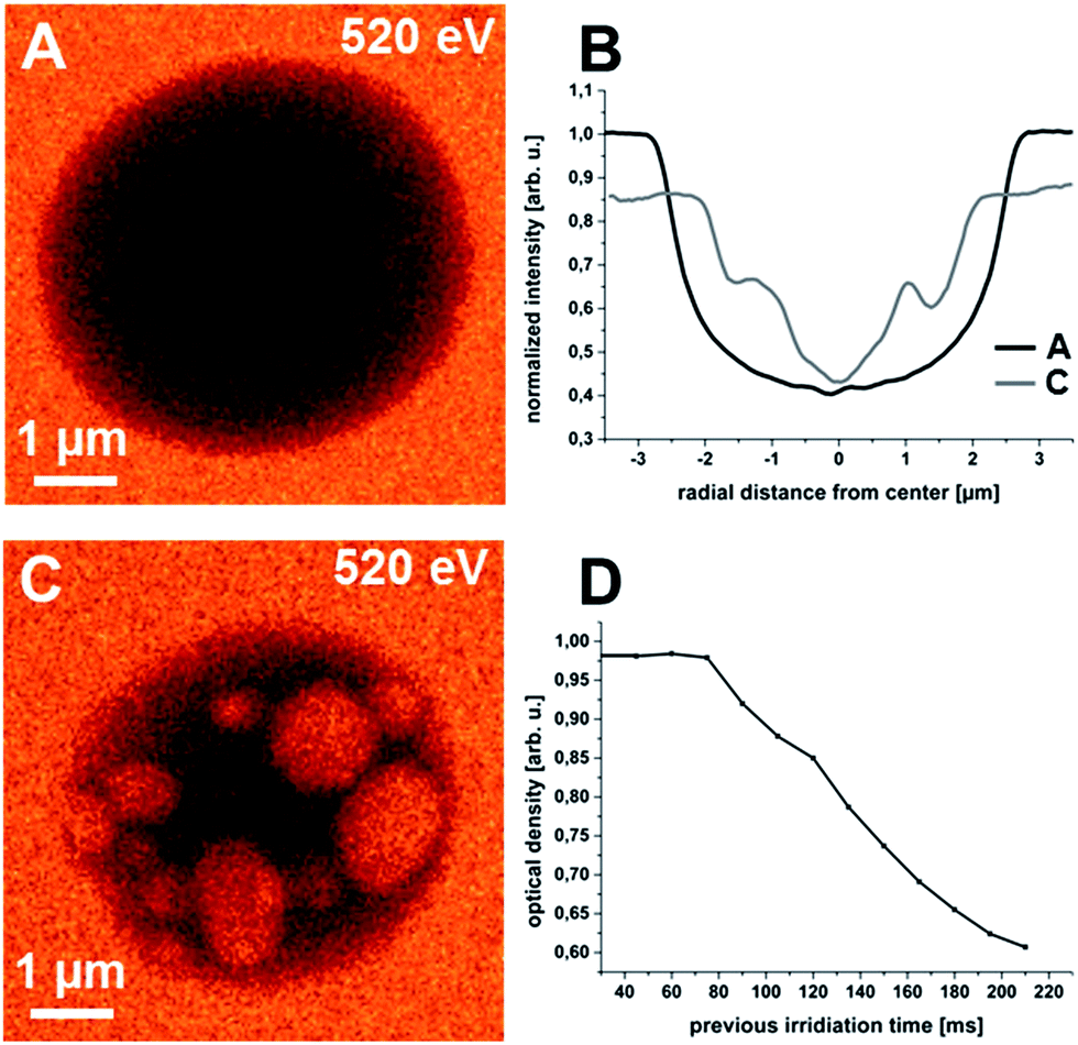 | ||
| Fig. 3 STXM micrographs of microcapsules in wet cells (dwell time 10 ms). (A and C) Exemplary micrographs from image series of same microcapsule showing constant degradation. (B) Radial profiles extracted from respective micrographs. (D) Decrease of average optical density with irradiation time from series of twelve images. | ||
Fig. 3B shows the corresponding radial profiles. The radial profiles show the decrease in particle diameter accompanied by an increase of the optical density of the surrounding matrix. The occurrence of the bright areas strongly affects the regular U-shape of the radial profiles and therefore, their evaluation is less meaningful for the degraded particles. In addition, changes in the background intensity outside the particle prevent a proper normalization to achieve absolute values for the profile height. Therefore Fig. 3D was added. It shows the dependence of the average optical density of the microcapsule (directly correlated with residual mass) with irradiation dose. For the initial five images we observe constant values. However, starting with the sixth micrograph of the recorded imaging series the average optical density decreases continuously.
TEM micrographs of ultra-thin cross-sections of the [Hmim][TFSA] microcontainers in epoxy resin prove the rigid and dense morphology of the cross-linked polymer shell.25 Investigations on the mechanical properties of similar polymer microcontainers corroborate these results.47 Furthermore, we do not expect a shrinking of the polymer shell due to the release of incorporated water, since P(EGDM-BMA) is highly hydrophobic.
Based on these considerations the experimental results lead to the conclusion that with ongoing irradiation an increasing number of holes perforate the polymer shell and water and IL are slowly exchanged. The increasing IL content of the water matrix leads to the decreasing transmitted intensity around the microcapsules (cf. Fig. 3B). Since [Hmim][TFSA] is hydrophobic, the extrusion is energetically unfavourable and very slow and the ingressing water forms discrete drops within the microcapsule that shine up as brighter regions within the particle at 520 eV. For very small microcapsules it was possible to decompose them almost completely after more than ten scans.
A schematic representation of the shell degradation, liquid exchange and water inclusion formation as it is concluded from the presented data is shown in Fig. 4. It represents a model of an intact microcontainer with homogeneous P(EGDM-BMA) shell and completely filled with [Hmim][TFSA] (Fig. 4A) and the same container after X-ray irradiation – now with perforated shell and water–IL exchange (Fig. 4B). We assume the IL to be solvated within the water matrix with time, since we did not detect clusters or small droplets of IL after shell decomposition. This assumption is corroborated by the enduring increase of the optical density of the liquid (water–IL) matrix (Fig. 3B).
 | ||
| Fig. 4 Scheme of microcapsule degradation in aqueous surrounding. (A) Intact microcapsule. (B) Microcapsule with water inclusions after severe damage of polymer shell. | ||
Although the degradation process was significantly slower within the liquid cells, it was not possible to record reasonable X-ray absorption spectra before significant decomposition. Therefore resonant irradiation for optimum contrast microscopy remains an open challenge so far.
4. Conclusions and outlook
In conclusion, we have demonstrated the potential of high-resolution soft X-ray microspectroscopy for a morphological and physico-chemical analysis of IL encapsulating polymer microcontainers. We showed the high sensitivity of this material to both, electron and X-ray irradiation due to shell degradation. The comparison of the TEM and STXM data for IL encapsulating microcontainers in the dry state shows the direct evidence for the higher energy deposition with high energy electrons, i.e., the faster, burst-like decomposition in TEM and the slow deliquescence in X-ray imaging. We propose the same degradation process in both cases, but the impinging energy density determines the deconstruction speed. In this regard it is important to mention that secondary electron induced processes play a major role in beam damage during X-ray absorption microscopy.46,48The inspection of degradation of the investigated microcontainers in aqueous surroundings opens up a more detailed understanding of the X-ray induced decomposition. Although the present study is not capable to resolve the spatial extent of the polymer shell, STXM is well-suited to monitor the morphological modifications. As can be observed from the image series in Fig. 3, the structural integrity of the microcontainers is largely maintained as derived from the overall particle shape and the change in permeability of the stabilizing shell leads to a continuous exchange of IL with the surrounding water. Due to the high cross-linking of the shell polymer, this effect is ascribed to the radiation induced formation of holes within the shell.
However, the sensitivity of these materials to high-resolution probes in terms of sample degradation limits the full structural characterization. In particular, the exact determination of the shell thickness of intact particles in liquid surroundings would be required with respect to in situ studies and the monitoring of chemical reactions in IL microcontainers.36 NEXAFS represents an advantageous spectroscopic tool that can be combined with high spatial resolution to differentiate between the polymer and the IL and lower doses might be applied for pure imaging without detailed chemical analysis in future studies with higher detection efficiency.
One approach to avoid the problem of rapid degradation could be made by the choice of a more stable shell polymer. However, it is not assured that the encapsulation process that depends on a complex coaction of the physical properties of shell material and IL in solution can easily be adapted to a suitable shell polymer. Since our investigations clearly indicate that the degradation of the microcapsules originates from structural damage of the polymer shell, we propose the use of a cryo stage to reduce the propagation of the X-ray induced degradation. The value of cryo stages was demonstrated successfully for several sample types prone to X-ray irradiation in full-field transmission X-ray microscopy.49,50
In terms of future applications employing the investigated shell degradation behaviour, high energy irradiation could be used as trigger for a controlled release of the embedded IL on a reasonable time scale. This could extent the common scope of IL applications and give rise to completely new mechanisms to influence and control step-by-step processes, such as catalytic reactions or separation processes.
Acknowledgements
We gratefully acknowledge experimental support by Drs J. Raabe and B. Watts from the PolLux beamline at the Swiss Light Source (SLS). We would like to thank Dr C. Kolbeck (FAU Erlangen) for fruitful discussions. The project was funded by the Bundesminister für Bildung und Forschung, contract 05 K10WEA. A.S. acknowledges funding through the Graduate School Molecular Science (GSMS).Notes and references
- M. J. Earle, J. Esperanca, M. A. Gilea, J. N. C. Lopes, L. P. N. Rebelo, J. W. Magee, K. R. Seddon and J. A. Widegren, Nature, 2006, 439, 831 CrossRef CAS PubMed.
- P. Wasserscheid, Nature, 2006, 439, 797 CrossRef CAS PubMed.
- N. V. Plechkova and K. R. Seddon, Chem. Soc. Rev., 2006, 37, 123 RSC.
- P. Wasserscheid and T. Welton, Ionic liquids in synthesis, Wiley-VCH, Weinheim, 2nd edn, 2008 Search PubMed.
- J. D. Holbrey and K. R. Seddon, Clean Technol. Environ., 1999, 1, 223 CrossRef.
- M. Smiglak, A. Metlen and R. D. Rogers, Acc. Chem. Res., 2007, 40(11), 1182 CrossRef CAS PubMed.
- H. Weingärtner, Angew. Chem., Int. Ed., 2008, 47, 654 CrossRef PubMed.
- P. Wasserscheid and W. Keim, Angew. Chem., Int. Ed., 2000, 39, 3772 CrossRef CAS.
- T. Welton, Coord. Chem. Rev., 2004, 248, 2459 CrossRef CAS PubMed.
- E. W. Castner Jr, C. J. Margulis, M. Maroncelli and J. F. Wishart, Annu. Rev. Phys. Chem., 2011, 62, 85 CrossRef PubMed.
- D. B. Kuang, P. Wang, S. Ito, S. M. Zakeeruddin and M. Gratzel, J. Am. Chem. Soc., 2006, 128, 7732 CrossRef CAS PubMed.
- D. R. MacFarlane, M. Forsyth, P. C. Howlett, J. M. Pringle, J. Sun, G. Annat, W. Neil and E. I. Izgorodina, Acc. Chem. Res., 2007, 40, 1165 CrossRef CAS PubMed.
- A. Berthod, M. J. Ruiz-Angel and S. Huguet, Anal. Chem., 2005, 77(13), 4071 CrossRef CAS PubMed.
- X. Han and D. W. Armstrong, Acc. Chem. Res., 2007, 40, 1079 CrossRef CAS PubMed.
- J. F. Fernandez, J. Neumann and J. Thoeming, Curr. Org. Chem., 2011, 15, 1992 CrossRef CAS.
- H.-P. Steinrück, J. Libuda, P. Wasserscheid, T. Cremer, C. Kolbeck, M. Laurin, F. Maier, M. Sobota, P. S. Schulz and M. Stark, Adv. Mater., 2011, 23, 2571 CrossRef PubMed.
- M. Haumann and A. Riisager, Chem. Rev., 2008, 108, 1474 CrossRef CAS PubMed.
- S. Werner, M. Haumann and P. Wasserscheid, Ann. Rev. Chem. Biomol. Eng., 2010, 1, 203 CrossRef CAS PubMed.
- N. V. N. Jyothi, P. M. Prasanna, S. N. Sakarkar, K. S. Prabha, P. S. Ramaiah and G. Y. Srawan, J. Microencapsulation, 2010, 27(3), 187 CrossRef CAS PubMed.
- W. W. Yang, Y. C. Lu, Z. Y. Xiang and G. S. Luo, React. Funct. Polym., 2007, 67, 81 CrossRef CAS PubMed.
- Z. Y. Xiang, Y. C. Lu, Y. Zou, X. C. Gong and G. S. Luo, React. Funct. Polym., 2008, 68, 1260 CrossRef CAS PubMed.
- H. Gao, J. Xing, X. Xiong, Y. Li, W. Li, Q. Liu, Y. Wu and H. Liu, Ind. Eng. Chem. Res., 2008, 47, 4414 CrossRef CAS.
- D. X. Chen, X. K. OuYang, Y. G. Wang, L. Y. Yang, D. Yu and C. H. He, Adv. Mat. Res., 2012, 557–559, 619 CAS.
- M. Okubo, Y. Konishi and H. Minami, Colloid Polym. Sci., 2001, 279, 519 CAS.
- H. Minami, H. Fukaumi, M. Okubo and T. Suzuki, Colloid Polym. Sci., 2013, 291, 45 CAS.
- T. Suzuki, H. Ichikawa, M. Nakai and H. Minami, Soft Matter, 2013, 9, 1761 RSC.
- J. Palomar, J. Lemus, N. Alonso-Morales, J. Bedia, M. A. Gilarranz and J. J. Rodriguez, Chem. Commun., 2012, 48, 10046 RSC.
- H.-P. Steinrück, Phys. Chem. Chem. Phys., 2012, 14, 5010 RSC.
- C. Hardacre, Annu. Rev. Mater. Res., 2005, 35, 29 CrossRef CAS.
- T. Nishi, T. Iwahashi, H. Yamane, Y. Ouchi, K. Kanai and K. Seki, Chem. Phys. Lett., 2008, 455, 213 CrossRef CAS PubMed.
- F. Rodrigues, D. Galante, G. M. do Nascimento and P. S. Santos, J. Phys. Chem. B, 2012, 116, 1491 CrossRef CAS PubMed.
- P. D'Angelo, A. Zitolo, V. Migliorati, E. Bodo, G. Aquilanti, J. L. Hazemann, D. Testemale, G. Mancini and R. Caminiti, J. Chem. Phys., 2011, 135, 074505 CrossRef PubMed.
- C. Déjugnat, K. Köhler, M. Dubois, G. B. Sukhorukov, H. Möhwald, T. Zemb and P. Guttmann, Adv. Mater., 2007, 19, 1331 CrossRef.
- G. Tzvetkov and R. H. Fink, Scr. Mater., 2008, 59, 348 CrossRef CAS PubMed.
- B. Graf-Zeiler, R. H. Fink and G. Tzvetkov, ChemPhysChem, 2011, 12, 3503 CrossRef CAS PubMed.
- G. Tzvetkov, B. Graf, P. Fernandes, A. Fery, F. Cavalieri, G. Paradossi and R. H. Fink, Soft Matter, 2008, 4, 510 RSC.
- J. Raabe, G. Tzvetkov, U. Flechsig, M. Böge, A. Jaggi, B. Sarafimov, M. G. C. Vernooij, T. Hutwelker, H. Ade, D. Kilcoyne, T. Tyliszczak, R. H. Fink and C. Quitmann, Rev. Sci. Instrum., 2008, 79, 113704 CrossRef CAS PubMed.
- J. Vila-Comamala, K. Jefimovs, J. Raabe, T. Pilvi, R. H. Fink, M. Senoner, A. Maaßdorf, M. Ritala and C. David, Ultramicroscopy, 2009, 109, 1360 CrossRef CAS PubMed.
- J. P. Armstrong, C. Hurst, R. G. Jones, P. Licence, K. R. J. Lovelock, C. J. Satterley and I. J. Villar-Garcia, Phys. Chem. Chem. Phys., 2007, 9, 982 RSC.
- R. Ge, C. Hardacre, L. Jacquemin, P. Nancarrow and D. W. Rooney, J. Chem. Eng. Data, 2008, 53, 2148 CrossRef CAS.
- E. G. Rightor, A. P. Hitchcock, H. Ade, R. D. Leapman, S. G. Urquhart, A. P. Smith, G. E. Mitchell, D. Fischer, H. J. Shin and T. Warwick, J. Phys. Chem. B, 1997, 101, 1950 CrossRef CAS.
- A. P. Hitchcock, J. J. Dynes, G. Johansson, J. Wang and G. Botton, Micron, 2008, 39, 741 CrossRef CAS PubMed.
- T. Coffey, S. G. Urquhart and H. Ade, J. Electron Spectrosc. Relat. Phenom., 2002, 122, 65 CrossRef CAS.
- J. O. Choi, J. A. Moore, J. C. Corelli, J. P. Silverman and H. Bakhru, J. Vac. Sci. Technol., B, 1988, 6, 2286 CAS.
- T. Beetz and C. Jacobsen, J. Synchrotron Radiat., 2002, 10, 280 CrossRef PubMed.
- J. Wang, C. Morin, L. Li, A. P. Hitchcock, A. Scholl and A. Doran, J. Electron Spectrosc. Relat. Phenom., 2009, 170, 25 CrossRef CAS PubMed.
- T. Tanaka, T. Suzuki, Y. Saka, P. B. Zetterlund and M. Okubo, Polymer, 2007, 48, 3836 CrossRef CAS PubMed.
- J. Cazaux, J. Microsc., 1997, 188, 106 CAS.
- C. A. Larabell and M. A. Le Gros, Mol. Biol. Cell, 2004, 15, 957 CrossRef CAS PubMed.
- G. Schneider, P. Guttmann, S. Heim, S. Rehbein, F. Mueller, K. Nagashima, J. Bernard Heymann, W. G. Müller and J. G. McNally, Nat. Methods, 2010, 7(12), 985 CrossRef CAS PubMed.
| This journal is © The Royal Society of Chemistry 2014 |