NH4CoPO4·H2O microbundles consisting of one-dimensional layered microrods for high performance supercapacitors†
Shaomei
Wang
a,
Huan
Pang
*ab,
Shanshan
Zhao
a,
Weifang
Shao
a,
Nannan
Zhang
a,
Jiangshan
Zhang
a,
Jing
Chen
a and
Sujuan
Li
a
aKey Laboratory for Clearer Energy and Functional Materials of Henan Province, College of Chemistry and Chemical Engineering, Anyang Normal University, Anyang, 455000 Henan, P. R. China
bState Key Laboratory of Coordination Chemistry, Nanjing University, Nanjing, 210093, Jiangsu, P. R. China. E-mail: huanpangchem@hotmail.com
First published on 28th October 2013
Abstract
Unique layered NH4CoPO4·H2O microbundles consisting of one-dimensional layered microrods are firstly synthesized by a facile hydrothermal method. As a result of novel layered structures, there are many nanolayered channels for the diffusion of ions and electrolytes. The preliminary supercapacitor investigation indicates that the specific capacitance of layered NH4CoPO4·H2O microbundle electrodes reaches up to 662 F g−1 at a current density of 1.5 A g−1 and remains at 520 F g−1 even at 15.0 A g−1. The cycle test shows excellent cycling performance of layered NH4CoPO4·H2O microbundle electrodes (the retention 92.7% of initial specific capacitance after 3000 cycles).
1. Introduction
Due to novel chemical–physical properties, layered micro/nanomaterials with unique architectures have been raised increasing attention for both scientific and technological interests in recent years.1–4 Among these layered nanomaterials, lots of artificial layered inorganic–organic components structures have been successfully synthesized, such as, ultrathin CoSe2 amine nanobelts,5 layered polydiacetylene/silica mesostructures,6 and tungstate-based inorganic–organic nanobelts.7 And layered double hydroxides (LDHs) have attracted much attention due to their layered feature and highly tunable interlayer composition.8–12 Besides, intense research efforts have been made on explorations of layered transition metal oxides.13–19 For example, layered LixMnyO2 (ref. 17) and cobalt-substituted manganese oxide has been synthesized with improved capacity and cycling performance as lithium battery electrodes.18Metal phosphates, especially for layered metal phosphates and phosphonates have been studied in the years 1987–1990.20,21 Carling and Yuan et al. obtained NH4MIIPO4·H2O (MII = Mn, Fe, Co, and Ni) by precipitations from aqueous solution.22,23 Zhang et al. have successfully reported a general method to prepare metal ammonium phosphate microspheres.24 However, there are nearly no reports on layered metal ammonium phosphate micro/nanomaterials.
Up until now, layered NH4CoPO4·H2O micro/nanostructures have not been synthesized through a facile method. In our previous work, we firstly found NH4CoPO4·H2O micro/nanostructures can be act as the promising electrodes for supercapacitors.25 Herein, we develop a facile hydrothermal method for synthesis of unique layered NH4CoPO4·H2O microbundles consisting of one-dimensional layered microrods. Moreover, we present the preliminary investigation on electrochemical performance of obtained layered NH4CoPO4·H2O microbundles for supercapacitors, indicating potential applications in high-performance supercapacitors.
2. Results and discussion
Fig. 1 shows XRD pattern of as-prepared samples. All peaks of the pattern are indexed to be in agreement with NH4CoPO4·H2O (JCPDS no. 21-0793). No peaks of other phosphites or phosphates were detected from these patterns. The peaks are strong and narrow, which indicate the good crystallinity of as-prepared samples. Good crystallinity of NH4CoPO4·H2O might be good to improve cycle life of electrodes for its stable structure, and it is not easy to be destroyed during the electrochemical process. In inset of Fig. 1, the schematic crystal structures of NH4CoPO4·H2O super cell (2 × 2 × 2 slabs) projected based on data of Inorganic Crystal Structure Data (ICSD)-15727. NH4CoPO4·H2O has the layered crystal structure and such layered crystal structure might improve the diffusion of ions and electrons.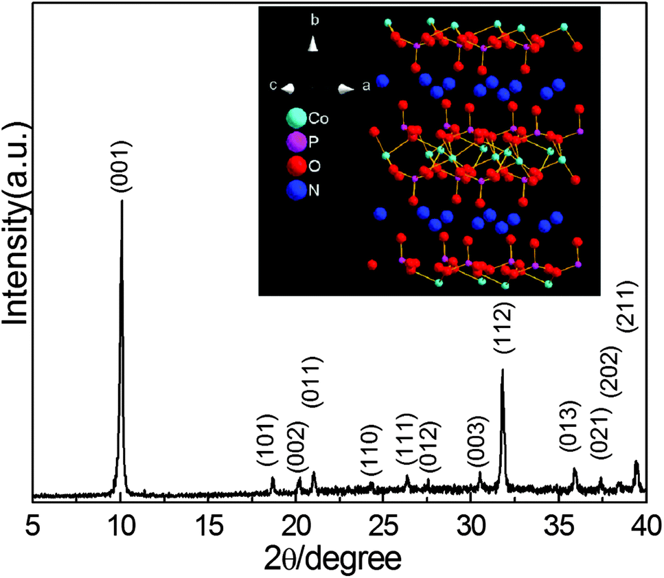 | ||
| Fig. 1 XRD patterns of as-prepared samples and in inset of it, crystal structures of NH4CoPO4·H2O super cell (2 × 2 × 2 slabs) projected based on data of ICSD-15727. | ||
The size and shape of as-prepared NH4CoPO4·H2O were examined by field emission scanning electron microscopy (FESEM) and transmission electron microscopy (TEM). Typical low-magnification SEM image in Fig. 2 shows that the morphology of samples is microbundles composed of many microrods. The size of a single microbundle is ∼50 μm.
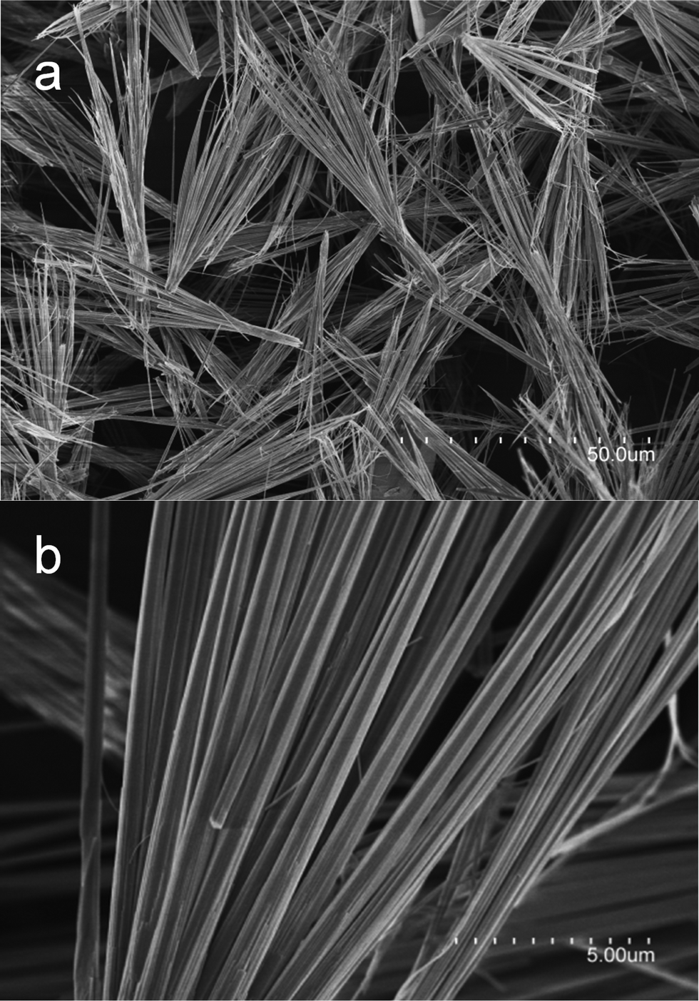 | ||
| Fig. 2 SEM images of as-prepared samples. | ||
A detailed morphology of the single microrod is measured by TEM and HRTEM images in Fig. 3. The microrod has not a uniform diameter, while it has a small end and a large end shown in Fig. 3a. The layered nanoscale properties were further revealed in Fig. 3b. It confirms the nanolayered structures and the size of a layer is about 17.54 Å, which is two times of a layer distance of crystal cell (8.77 Å) in inset of Fig. 1. Fig. 3c show the selected area electron diffraction (SAED) pattern and the high-resolution (HR) TEM images taken from the small end of a microrod shown in Fig. 3a, which demonstrates the highly crystalline nature of the product and may be described as a single crystal with [010] growth direction. The measured distances of the neighboring lattice fringes in Fig. 3c are 2.40 Å, corresponding well to the (020) lattice spacing of NH4CoPO4·H2O.
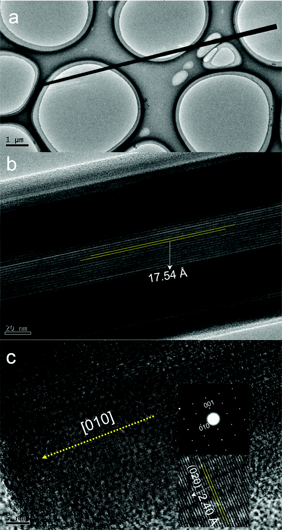 | ||
| Fig. 3 (a) Corresponding TEM image, and (b and c) HRTEM images, and SAED patterns. | ||
We also explored the possible formation process of NH4CoPO4·H2O microbundles, and found the reaction time affected the morphology of the product. The product was synthesized under different hydrothermal conditions (seen in ESI Fig. S1†). From ESI Fig. S1a,† microplate clusters were obtained under hydrothermal condition for 8 hours. After hydrothermal condition for 16 hours, many microrods were obtained, and some microbundles assembled short nanorods were observed among these microrods in ESI Fig. S1b.† And after 32 hours of hydrothermal condition, short NH4CoPO4·H2O microbundles assembled short microrods were largely synthesized in ESI Fig. S1c.† When further maintained for 48 hours, long NH4CoPO4·H2O microbundles assembled short microrods have been successfully synthesized, which have formed from short microbundles in Fig. 2.
To gain further insight into the specific surface area of layered NH4CoPO4·H2O microbundles, Brunauer–Emmett–Teller (BET) measurements were performed. And the N2 adsorption–desorption isotherms of layered NH4CoPO4·H2O microbundles were shown in Fig. 4. The BET surface area of layered NH4CoPO4·H2O microbundles is 89.5 m2 g−1. The pore-size distribution (in inset of Fig. 4) was determined by using the Barrett–Joyner–Halenda (BJH) method from the desorption branch of the isotherm. The average pore diameter of the sample is 1.5–6 nm, which is attributed to the layered structures assembled. As widely reported, a high surface area and layered structures usually gives rise to many channels for contacting the electrolyte with surface-interfaces of novel micro/nanostructures.
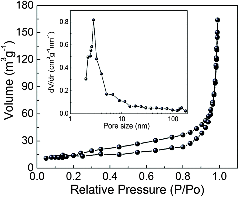 | ||
| Fig. 4 Typical N2 adsorption–desorption isotherms and pore-size distribution curve. | ||
In Scheme 1, it clearly exhibits a layered NH4CoPO4·H2O microbundles model image. NH4CoPO4·H2O microbundles are made up of many layered microrods, which means there are thousands of nanochannels in the microbundle. What is more, thousands of nanochannels might largely improve diffusion of ions and electrolytes, and the microbundle might offer a stable skeleton for ions intercalation–extraction.
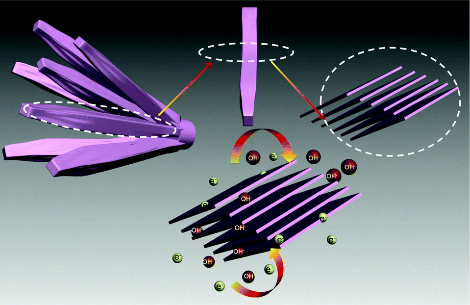 | ||
| Scheme 1 A layered NH4CoPO4·H2O microbundles model image and possible charge–discharge process. | ||
Cyclic voltammogram (CV) studies were employed to characterize the capacitive performance of layered NH4CoPO4·H2O microbundles. Fig. 5a shows CVs of the layered NH4CoPO4·H2O microbundle electrodes (a mass loading of 5 mg) in 3.0 M KOH electrolyte at different scan rates in the range 5–100 mV s−1. As seen in the Fig. 4a, the shapes are different from that of electric double-layer capacitance, suggesting that the capacity mainly results from pseudocapacitive capacitance, and it indicates that the Faradaic pseudocapacitive property of layered NH4CoPO4·H2O microbundles is based on the surface redox mechanism of Co2+ to Co3+ at the surface.
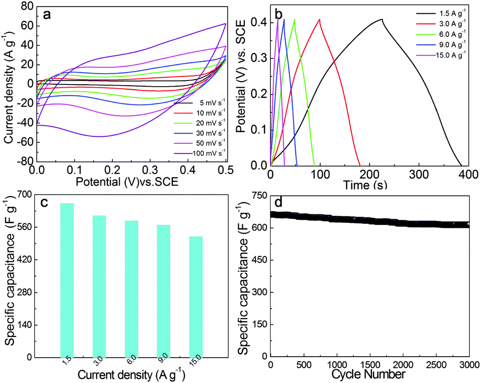 | ||
| Fig. 5 (a) Cyclic voltammetry experiments within a 0.0–0.50 V range at a scan rate 5–100 mV s−1 were performed on the layered NH4CoPO4·H2O microbundle electrodes in 3.0 M KOH electrolytes at room temperature, (b) the galvanostatic charge–discharge curves of layered NH4CoPO4·H2O microbundle electrodes during current densities were 1.5–15.0 A g−1 in 3.0 M KOH electrolytes, (c) specific capacitances of layered NH4CoPO4·H2O microbundle electrodes derived from the discharging curves at the current density of 1.5–15.0 A g−1 in 3.0 M KOH electrolytes, (d) charge–discharge cycling test at the current density of 1.5 A g−1 in 3.0 M KOH electrolytes. | ||
Chronopotentiometry (CP) curves at different current densities are shown in Fig. 5b. The symmetrical characteristic of charging–discharging curves is good, which means that the layered NH4CoPO4·H2O microbundle electrodes with excellent electrochemical capability and redox process are reversible. The relationship between the specific capacitances calculated by CP curves and current densities are given in Fig. 5c. Based on the CP curves, layered NH4CoPO4·H2O microbundle electrodes have the large specific capacitance and reach up to 662 F g−1 at a current density of 1.5 A g−1 and remain at 520 F g−1 even at 15.0 A g−1. The specific capacitance of layered NH4CoPO4·H2O microbundles is significantly better than some cobalt based phosphates micro/nanomaterials, such as our previous results – NH4CoPO4·H2O microflowers (<340 F g−1 at 1.5 A g−1),25 cobalt phosphite (Co11(HPO3)8(OH)6) microarchitectures (<312 F g−1 at 1.5 A g−1),26 and cobalt pyrophosphate (Co2P2O7) nano/microstructures (367 F g−1 at 0.625 A g−1),27 but lower than other supercapacitor materials.28–31
It is very important for electrode materials to have good specific capacitance retention. Supercapacitors should work steadily and safely, which requires the specific capacitance of electrode materials to change as little as possible. Relationships of the specific capacitance against cycling number of layered NH4CoPO4·H2O microbundle electrodes are shown in Fig. 5d. It shows its excellent specific capacitance retention under at 1.5 A g−1. After 300 continuous charge–discharge cycles, layered NH4CoPO4·H2O microbundle electrodes almost retain the same specific capacitance as its initial value. More importantly, layered NH4CoPO4·H2O microbundle electrodes still retain more than 92.7% of its specific capacitance after 3000 continuous charge–discharge cycles.
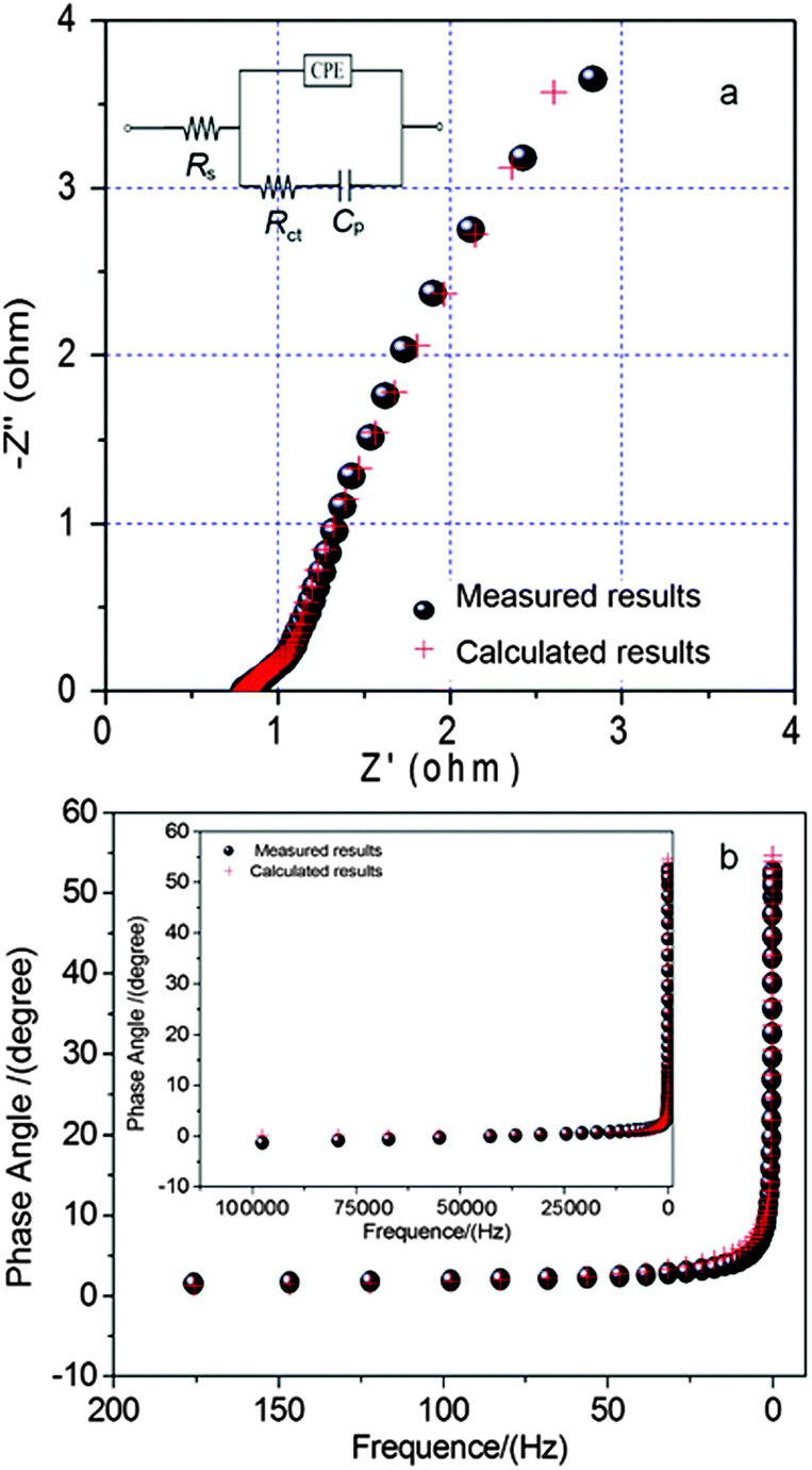
To identify the exact electrical conductivity of electrodes, we have measured EIS spectrum of layered NH4CoPO4·H2O microbundle electrodes (0 cycle) at room temperature in the frequency range 0.01–105 Hz under open-circuit conditions. Fig. 6 shows the EIS of layered NH4CoPO4·H2O microbundle electrodes at room temperature and its calculated curve by ZSimpWin software. An equivalent circuit used to fit the impedance curve is given in inset of Fig. 6a, which is similar to the circuit employed for the working electrode of supercapacitor. The EIS data can be fitted by a bulk solution resistance Rs, a charge-transfer Rct and a pseudocapacitive element Cp from redox process of electrode materials, and a CPE to account for the double-layer capacitance. The charge-transfer resistance Rct of all the sample was calculated by ZSimpWin software, and from the calculated results, we found that Rct of layered NH4CoPO4·H2O microbundle electrodes is 4.7 Ω. This clearly demonstrates the reduced charge-transfer resistance of the layered NH4CoPO4·H2O microbundle electrodes. In addition, the charge-transfer resistance Rct, also called Faraday resistance, is a limiting factor for the specific power of the supercapacitor. It is the low Faraday resistance that results in the high specific power of layered NH4CoPO4·H2O microbundle electrodes. This layered structure surface-interface character might also decrease the polarization of the electrode, and thus increase the capacity. The phase angles for impedance plots of layered NH4CoPO4·H2O microbundle electrodes and its calculated curve by ZSimpWin software were observed in Fig. 5b. These phase angles are nearly to 55° in the low frequencies clearly, which means that the layered NH4CoPO4·H2O microbundles allow ions or electrolyte transfer to occur quickly.
 | ||
| Fig. 6 (a) The electrochemical impedance spectra (EIS) of the electrodes at room temperature and its corresponding calculated curve, in inset of (a) the equivalent circuit for the electrochemical impedance spectrum, and (b) the phase angles for impedance plots and its corresponding calculated curve. | ||
The NH4CoPO4·H2O samples obtained before (0 cycle) and after different charging–discharging cycles (1 cycle, 500 cycle, 1000 cycle, 3000 cycle) are further explored by IR and HRTEM measurements (seen in ESI Fig. S2 and S3†). From IR tests in ESI Fig. S2,† five samples almost show the same spectrum, it indirectly deduces that NH4CoPO4·H2O is stable even after 3000 cycle. Detailed information of nanostructures is revealed by HRTEM. It is seen that the nanolayer structure is stable after 500 cycle in ESI Fig. S3.† However, due to ions intercalation-extraction, the nanolayer structure is partly destroyed after 1000 cycle. The phenomenon is enhanced by further prolonging the charging–discharging to 3000 cycle.
The change of nanolayer structures is also proved by XRD patterns of layered NH4CoPO4·H2O microbundles before (0 cycle) and after different charging–discharging cycles (1 cycle, 500 cycle, 1000 cycle, 3000 cycle, seen in Fig. 7). It is found that the intensity of crystal plane (001) has become weak with cycle numbers increasing. More importantly, the (001) peak of samples after 3000 cycles has shifted a little into the small angle of diffraction, which might be caused by ions intercalation into nanolayer structures in Fig. 7b.
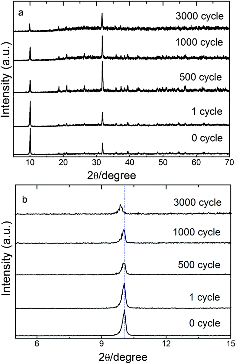 | ||
| Fig. 7 XRD patterns of layered NH4CoPO4·H2O microbundles before (0 cycle) and after different charging–discharging cycles (1 cycle, 500 cycle, 1000 cycle, 3000 cycle). (a) From 5° to 70°; (b) from 5° to 15°. | ||
In order to ascertain the oxidation state of cobalt during charging–discharging proceeding, XPS spectra of layered NH4CoPO4·H2O microbundles before (0 cycle) and after different charging–discharging cycles (1 cycle, 500 cycle, 1000 cycle, 3000 cycle) have been shown in Fig. 8. For the materials (0 cycle and 1 cycle), the Co 2p3/2 main spectral peaks are at about 781 eV with their satellites at the range of 785–786 eV. These results are close to those reported for Co2+ in Co(OH)2 and in Co-contained LDHs.32–40 The binding energy differences between the Co 2p3/2 and Co 2p1/2 main peaks are around 16.0 eV which is also near to 15.7 eV – a literature value for a cobalt hydrotalcite-like compound.41 However, for the sample (1000 cycle and 3000 cycle), the Co 2p3/2 main peak is located at 780.4 ± 0.2 eV, and the Co 2p1/2 main peak is 795.3 ± 0.2 eV, respectively. These characteristics are similar to those of CoOOH in a report.32 Moreover, from the O1s spectra (Fig. 8b, for samples 1000 cycle and 3000 cycle), a spectral peak at around 532 eV becomes a little wider, indicating that some Co2+ ions on the surfaces are partly oxidized.41 It means that the oxidization of NH4CoPO4·H2O microbundles' surface can be intensified with cycle numbers increasing. Like CoAl-layered double hydroxide composites, we have proposed the possible mechanism – eqn (1) to explain the intercalation/deintercalation of ions in NH4CoPO4·H2O microbundles:
| NH4CoPO4·H2O + OH− = NH4[Co(OH)PO4]·H2O + e− | (1) |
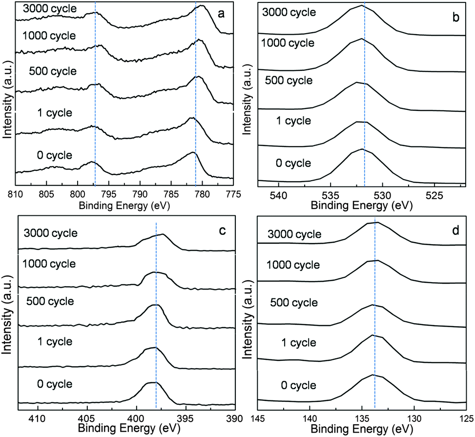 | ||
| Fig. 8 X-ray photoelectron spectra (XPS) of layered NH4CoPO4·H2O microbundles before (0 cycle) and after different charging–discharging cycles (1 cycle, 500 cycle, 1000 cycle, and 3000 cycle), (a) Co 2p peak; (b) O 1s peak; (c) N 1s peak, (d) P 2p peak. | ||
Typical electrochemical impedance spectroscopy of the layered NH4CoPO4·H2O microbundle electrodes before (0 cycle) and after different charging–discharging cycles (1 cycle, 500 cycle, 1000 cycle, 3000 cycle) have been shown in Fig. 9. The higher equivalent series resistance (ESR) value, (the equivalent circuit is shown in inset of Fig. 6a), indicates the lower electrical conductivity of the sample and vice versa.42 It can be seen that the ESR values in the Nyquist plot of the layered NH4CoPO4·H2O microbundles electrode are very small and increase a little after long charge–discharge cycling (Fig. 9). Moreover, these phase angles have changed a little except that of the electrode after 3000 cycle, which means ions or electrolyte transfer to occur quickly even after long charge–discharge cycling.
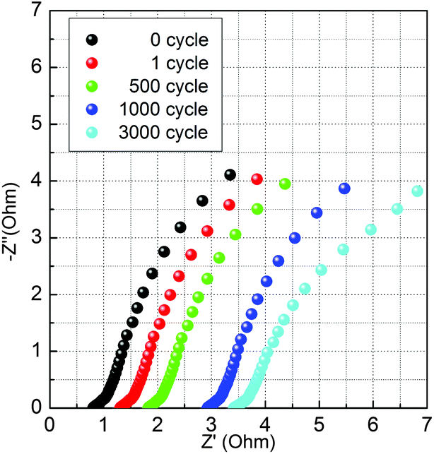 | ||
| Fig. 9 Typical electrochemical impedance spectroscopy measurements of layered NH4CoPO4·H2O microbundle electrodes before-0 cycle, and after different charging–discharging cycles-1 cycle, 500 cycle, 1000 cycle and 3000 cycle. | ||
While a three-electrode cell is valuable for determining electrochemical-specific material characteristics, a two-electrode test cell mimics the physical configuration, internal voltages and charge transfer that occurs in a packaged ultracapacitor and thus providing the best indication of an electrode material's performance.43,44 Charge–discharge curves of layered NH4CoPO4·H2O microbundles–graphene nanosheets asymmetric supercapacitors measured at different current densities in 3.0 M KOH solutions are shown in Fig. 10a by ref. 45's method. Typical charge–discharge curves of cells from 0 to 1.1 V at different current densities are respectively shown in Fig. 10a. On the curve in 3.0 M KOH, the cell voltage is sharply increased from 0 to ca. 1.1 V when the charging current is applied, attributable to the open-circuit potential differences between graphene and layered NH4CoPO4·H2O microbundles. Then, the cell voltage is gradually increased, and a quasi-linear voltage-time response is visible between 0 and 1.1 V, which is the typical capacitor behavior. The Ragone plots of layered NH4CoPO4·H2O microbundles–graphene nanosheets asymmetric supercapacitors in 3.0 M KOH solutions obtained from the discharge curves are presented in Fig. 10b. The specific energy of cell in 3.0 KOH solution even reaches ca. 26.6 W h kg−1 under a relatively low power operation (e.g., 852 W kg−1). Accordingly, NH4CoPO4·H2O microbundles–graphene nanosheets asymmetric supercapacitors are proposed to be an energy oriented asymmetric supercapacitors in 3.0 KOH solution electrolyte. However, the specific energy of cell in 3.0 KOH solution is not larger than ref. 45–48.
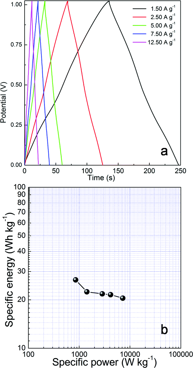 | ||
| Fig. 10 (a) Charge–discharge curves of layered NH4CoPO4·H2O microbundles–graphene nanosheets asymmetric supercapacitors measured at different current densities in 3.0 M KOH solutions; (b) the Ragone plot of layered NH4CoPO4·H2O microbundles–graphene nanosheets asymmetric supercapacitors in 3.0 M KOH solutions. | ||
3. Conclusions
In this work, unique layered NH4CoPO4·H2O microbundles have been firstly synthesized through a hydrothermal method. More importantly, layered NH4CoPO4·H2O microbundles show novel layered surface-interface condition, which plays key roles to ions intercalating/extracting into/out and electrolyte accesses. The measurement of electrochemical properties of layered NH4CoPO4·H2O microbundles is an important work, which successfully illustrates layered NH4CoPO4·H2O microbundles materials can be applied as an electroactive material for supercapacitor. Despite specific capacitance of layered NH4CoPO4·H2O microbundles materials is not much larger than some previous materials,45–48 it is a good example to prove that physical and chemical properties of nano/microstructured materials are related with their structures, and the precise control of morphology of nanomaterials will serve for controlling the performance. Exploring the electrochemical characteristics of novel nano/micromaterials might direct a new generation of supercapacitor materials.4. Experimental section
Synthesis of unique layered NH4CoPO4·H2O microbundles
In a typical synthesis, 0.10 g of cobalt nitrate and 0.15 g ammonium tertiary phosphate were added into 20.0 mL of distilled water under stirring until salts were completely dissolved. The solution mixture was put in a Teflon-lined stainless steel autoclave and heated at 220.0 °C for 48.0 h. After reaction, purple precipitates were obtained. The precipitates were thoroughly washed with distilled water and ethanol to remove ions possibly remaining in the final products, and dried at room temperature in air.Characterizations
The morphology of as-prepared samples was observed by a JEOL JSM-6701F field-emission scanning electron microscope (FE-SEM) at an acceleration voltage of 5.0 kV. The phase analyses of the samples were performed by X-ray diffraction (XRD) on a Rigaku-Ultima III with Cu Kα radiation (λ = 1.5418 Å). Nitrogen adsorption–desorption measurements were performed on a Gemini VII 2390 Analyzer at 77 K using the volumetric method. The specific surface area was obtained from the N2 adsorption–desorption isotherms and was calculated by the Brunauer–Emmett–Teller (BET) method. Transmission electron microscopy (TEM) images and HRTEM images were captured on the JEM-2100 instrument microscopy at an acceleration voltage of 200 kV. Fourier transform infrared spectra (FT-IR) were collected in the region from 400 to 4000 cm−1 at room temperature using a Nicolet 670 spectroscopy on KBr pellets. The XP spectra were obtained using a PHI5000 Versa Probe.Electrochemical study on layered NH4CoPO4·H2O microbundle electrodes was carried out on a CHI 660D electrochemical working station (Shanghai Chenhua Instrument, Inc.). All electrochemical performances were carried out in a conventional three-electrode system equipped with platinum electrode and a saturated calomel electrode (SCE) as counter and reference electrodes, respectively. Before electrochemical measurement, we have purged out O2 from the solution by the inert gas – Ar. The working electrode was made from mixing of active materials (layered NH4CoPO4·H2O microbundles), acetylene black, and PTFE (polytetrafluoroethylene) with a weight ratio of 80![[thin space (1/6-em)]](https://www.rsc.org/images/entities/char_2009.gif) :15:5, coating on a piece of foamed nickel foam of about 1 cm2, and pressing it to be a thin foil at a pressure of 5.0 MPa. The typical mass load of electrode material is 5.0 mg. The electrolyte was 3.0 M KOH solution. Cyclic voltammetry and galvanostatic charge–discharge methods were used to investigate capacitive properties of layered NH4CoPO4·H2O microbundles packages electrode. And electrochemical impedance spectroscopy measurements of all the samples were conducted at open circuit voltage in the frequency range of 100 kHz to 0.01 Hz with AC voltage amplitude of 5 mV by using PARSTAT2273.
:15:5, coating on a piece of foamed nickel foam of about 1 cm2, and pressing it to be a thin foil at a pressure of 5.0 MPa. The typical mass load of electrode material is 5.0 mg. The electrolyte was 3.0 M KOH solution. Cyclic voltammetry and galvanostatic charge–discharge methods were used to investigate capacitive properties of layered NH4CoPO4·H2O microbundles packages electrode. And electrochemical impedance spectroscopy measurements of all the samples were conducted at open circuit voltage in the frequency range of 100 kHz to 0.01 Hz with AC voltage amplitude of 5 mV by using PARSTAT2273.
Acknowledgements
This work is supported by the Program for New Century Excellent Talents (NCET-13-0645) and National Natural Science Foundation of China (NSFC-21201010, 21071006, U1304504 and 21105002), the Science & Technology Foundation of Henan Province (122102210253, 13A150019), and the China Postdoctoral Science Foundation (2012M521115).Notes and references
- A. R. Armstrong and P. G. Bruce, Nature, 1996, 381, 499 CrossRef CAS.
- K. Takada, H. Sakurai, E. Takayama-Muromachi, F. Izumi, R. A. Dilanian and T. Sasaki, Nature, 2003, 422, 53 CrossRef CAS PubMed.
- Z. P. Liu, R. Z. Ma, M. Osada, N. Iyi, Y. Ebina, K. Takada and T. Sasaki, J. Am. Chem. Soc., 2006, 128, 4872 CrossRef CAS PubMed.
- C. H. Chen, V. M. B. Crisostomo, W. N. Li, L. P. Xu and S. L. Suib, J. Am. Chem. Soc., 2008, 130, 14390 CrossRef CAS PubMed.
- M. R. Gao, W. T. Yao, H. B. Yao and S. H. Yu, J. Am. Chem. Soc., 2009, 131, 7486 CrossRef CAS PubMed.
- H. S. Peng, J. Tang, J. B. Pang, D. Y. Chen, L. Yang, H. S. Ashbaugh, C. J. Brinker, Z. Z. Yang and Y. F. Lu, J. Am. Chem. Soc., 2005, 127, 12782 CrossRef CAS PubMed.
- D. L. Chen and Y. Sugahara, Chem. Mater., 2007, 19, 1808 CrossRef CAS.
- B. Sels, D. De Vos, M. Buntinx, F. Pierard, A. Kirsch-De Mesmaeker and P. Jacobs, Nature, 1999, 400, 855 CrossRef CAS PubMed.
- J. H. Choy, S. Y. Kwak, Y. J. Jeong and J. S. Park, Angew. Chem., Int. Ed., 2000, 39, 4042 CrossRef CAS.
- M. Darder, M. Lopez-Blanco, P. Aranda, F. Leroux and E. Ruiz-Hitzky, Chem. Mater., 2005, 17, 1969 CrossRef CAS.
- R. Z. Ma, Z. P. Liu, K. Takada, N. Iyi, Y. Bando and T. Sasaki, J. Am. Chem. Soc., 2007, 129, 5257 CrossRef CAS PubMed.
- H. B. Yao, H. Y. Fang, Z. H. Tan, L. H. Wu and S. H. Yu, Angew. Chem., Int. Ed., 2010, 49, 2140 CrossRef CAS PubMed.
- H. Hata, Y. Kobayashi, V. Bojan, W. J. Youngblood and T. E. Mallouk, Nano Lett., 2008, 8, 794 CrossRef CAS PubMed.
- C. Tagusagawa, A. Takagaki, S. Hayashi and K. Domen, J. Am. Chem. Soc., 2008, 130, 7230 CrossRef CAS PubMed.
- M. A. Bizeto, A. L. Shiguihara and V. R. L. Constantino, J. Mater. Chem., 2009, 19, 2512 RSC.
- K. Maeda, M. Eguchi, W. J. Youngblood and T. E. Mallouk, Chem. Mater., 2009, 21, 3611 CrossRef CAS.
- A. R. Armstrong, A. J. Paterson, A. D. Robertson and P. G. Bruce, Chem. Mater., 2002, 14, 710 CrossRef CAS.
- S. H. Lee, T. W. Kim, D. H. Park, J. H. Choy, S. J. Hwang, N. Z. Jiang, S. E. Park and Y. H. Lee, Chem. Mater., 2007, 19, 5010 CrossRef CAS.
- D. W. Kim, Y. D. Ko, J. G. Park and B. K. Kim, Angew. Chem., Int. Ed., 2007, 46, 6654 CrossRef CAS PubMed.
- N. J. Clayden, J. Chem. Soc., Dalton Trans., 1987, 1877 RSC.
- G. Alberti, M. G. Bernasconi and M. Casciola, React. Polym., 1989, 11, 245 CrossRef CAS.
- S. G. Carling, P. Day and D. Visser, Inorg. Chem., 1995, 34, 3917 CrossRef CAS.
- A. Q. Yuan, J. L. Wu, J. Bai, S. M. Ma, Z. Y. Huang and Z. F. Tong, J. Chem. Eng. Data, 2008, 53, 1066 CrossRef CAS.
- C. F. Zeng, W. W. Ji and L. X. Zhang, CrystEngComm, 2012, 14, 3008–3011 RSC.
- H. Pang, Z. Yan, W. Wang, J. Chen, J. S. Zhang and H. H. Zheng, Nanoscale, 2012, 4, 5946–5953 RSC.
- H. Pang, Y. Y. Liu, J. Li, Y. H. Ma, G. C. Li, Y. N. Ai, J. Chen, J. S. Zhang and H. H. Zheng, Nanoscale, 2013, 5, 503–507 RSC.
- H. Pang, Z. Yan, Y. Ma, G. Li, J. Chen, J. Zhang, W. Du and S. Li, J. Solid State Electrochem., 2013, 17, 1383–1391 CrossRef CAS PubMed.
- C. Z. Yuan, X. G. Zhang, L. H. Gao, B. Su and L. F. Shen, J. Mater. Chem., 2009, 19, 5772–5777 RSC.
- Z. Lu, Z. Chang, W. Zhu and X. M. Sun, Chem. Commun., 2011, 47, 9651–9653 RSC.
- B. Qu, Y. Chen, M. Zhang, L. Hu, D. Lei, B. Lu, Q. Li, Y. Wang, L. Chen and T. H. Wang, Nanoscale, 2012, 4, 7810 RSC.
- H. Pang, Z. Z. Yan, Y. Y. Wei, X. X. Li, J. Li, L. Zhang, J. Chen, J. S. Zhang and H. H. Zheng, Part. Part. Syst. Charact., 2013, 30, 287–295 CrossRef CAS.
- J. Yang, H. Liu and W. N. Martens, J. Phys. Chem. C, 2009, 114, 111–119 Search PubMed.
- L. J. Zhang, X. G. Zhang, L. F. Shen, B. Gao, L. Hao, X. J. Lu, F. Zhang, B. Ding and C. Z. Yuan, J. Power Sources, 2012, 199, 395–401 CrossRef CAS PubMed.
- K. M. Ismail and W. A. Badawy, J. Appl. Electrochem., 2000, 30, 1303–1311 CrossRef CAS.
- Y. G. Wang, L. Cheng and Y. Y. Xia, J. Power Sources, 2006, 153, 191–196 CrossRef CAS PubMed.
- M. Hu, X. D. Ji, L. X. Lei and X. W. Lu, Electrochim. Acta, 2013, 105, 261–274 CrossRef CAS PubMed.
- J. H. Fang, M. Li, Q. Q. Li, W. F. Zhang, Q. L. Shou, F. Liu, X. B. Zhang and J. P. Cheng, Electrochim. Acta, 2012, 85, 248–255 CrossRef CAS PubMed.
- Z. Y. Lu, W. Zhu, X. D. Lei, G. R. Williams, D. O'Hare, Z. Chang, X. M. Sun and X. Duan, Nanoscale, 2012, 4, 3640 RSC.
- X. Zhao, Y. Zhang, S. Xu, X. Lei and F. Zhang, J. Phys. Chem. C, 2012, 116, 5288–5294 CAS.
- N. V. Kosova, E. T. Devyatkina and V. V. Kaichev, J. Power Sources, 2007, 174, 735–740 CrossRef CAS PubMed.
- J. T. Sampanthar and H. C. Zeng, Chem. Mater., 2001, 13, 4722–4730 CrossRef CAS.
- G. A. Snook, P. Kao and A. S. Best, J. Power Sources, 2011, 196, 1 CrossRef CAS PubMed.
- M. D. Stoller and R. S. Ruoff, Energy Environ. Sci., 2010, 3, 1294–1301 CAS.
- Y. Gogotsi and P. Simon, Science, 2011, 334, 918 CrossRef PubMed.
- C.-C. Hu, J.-C. Chen and K.-H. Chang, J. Power Sources, 2013, 221, 128 CrossRef CAS PubMed.
- C.-L. Liu, K.-H. Chang, C.-C. Hu and W.-C. Wen, J. Power Sources, 2012, 217, 184 CrossRef CAS PubMed.
- H. Pang, S. Wang, G. Li, Y. Ma, J. Li, X. Li, L. Zhang, J. Zhang and H. Zheng, J. Mater. Chem. A, 2013, 1, 5053 CAS.
- H. Pang, C. Z. Wei, Y. H. Ma, S. S. Zhao, G. C. Li, J. S. Zhang, J. Chen and S. J. Li, ChemPlusChem, 2013, 78, 546–553 CrossRef CAS.
Footnote |
| † Electronic supplementary information (ESI) available. See DOI: 10.1039/c3ra45977b |
| This journal is © The Royal Society of Chemistry 2014 |