Polypyrrole nanotubes: mechanism of formation

Jitka Kopecká a, Dušan Kopecký a, Martin Vrňata *a, Přemysl Fitl a, Jaroslav Stejskal b, Miroslava Trchová b, Patrycja Bober b, Zuzana Morávková b, Jan Prokeš c and Irina Sapurina d
aFaculty of Chemical Engineering, Institute of Chemical Technology Prague, 166 28 Prague 6, Czech Republic. E-mail: martin.vrnata@vscht.cz; Fax: +420 220 444 334; Tel: +420 220 443 383
bInstitute of Macromolecular Chemistry, Academy of Sciences of the Czech Republic, 162 06 Prague 6, Czech Republic
cCharles University in Prague, Faculty of Mathematics and Physics, 180 00 Prague 8, Czech Republic
dInstitute of Macromolecular Compounds, Russian Academy of Sciences, St. Petersburg 199004, Russian Federation

Received 15th October 2013 , Accepted 14th November 2013

First published on 14th November 2013


Abstract

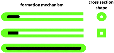
This article presents a contribution to better understanding of the processes which take place during the synthesis of polypyrrole nanotubes using a structure-guiding agent, methyl orange. Polypyrrole was prepared by oxidation of pyrrole monomer with iron(III) chloride. In the presence of methyl orange, the formation of nanotubes was observed instead of the globular morphology. Two reaction schemes with reversed additions of oxidant and monomer have been tested and they show remarkable influence on the produced morphology. Nanotubes with circular or rectangular profiles and diameters from tens to hundreds of nanometres have been obtained. FTIR and Raman spectra were used to assess the molecular structure of polypyrrole and detect residual methyl orange in the samples. The conductivity of nanotubes compressed into pellets was as high as 68 S cm−1. The mechanism of nanotubular formation starting at the nucleus produced with the participation of organic dye is proposed. The growth of a nanotube, however, proceeds in the absence of a template. An alternative mechanism for the formation of nanotubes, the coating of solid templates with a polypyrrole overlayer, is also discussed.


Introduction

The last decade of conducting polymer research has been characterized by increasing interest in the control of their morphology at the nanoscale. Among them polypyrrole (PPy) and polyaniline (PANI) have been most studied. In particular, one-dimensional structures, such as nanorods, nanotubes or nanofibres are promising1–3 due to their possible uses in sensors,4 energy storage,5 electrocatalysis,6 electrorheology,7 electromagnetic interference shielding,8 and biomedicine,9 or in the conversion to nitrogen-containing carbon materials.10 They are better suited for the charge transport than globular forms and also their larger specific surface area is of benefit in many applications. More complex three-dimensional hierarchical morphologies have also been reported11 but they are usually generated only by non-conducting aniline oligomers.

There are three basic approaches to the preparation of one-dimensional conducting polymer nanostructures: (1) hard-template methods using solid inorganic membranes or fibres for the deposition of conducting polymers,12–15 (2) soft-template methods employing supramolecular assemblies of auxiliary organic substances, such as surfactant micelles16–18 or aggregates of dyes19 as structure-guiding agents20–22 and, finally, (3) polymer nanotubes or nanofibres can also be produced without any external template, as well documented for PANI.1,3,23 The preparation of uniform nanotubular or nanofibrillar morphologies in large quantities required for practical use, however, still remains an important research issue.

The principles underlying the formation of one-dimensional morphologies have to be similar for PANI and PPy. The preference of the PANI or PPy depends on the potential applications. While PANI displays acid–base transition associated with colour and conductivity changes, which is well applicable in sensors, PPy is usually preferred in biomedical uses, where the toxic hazards associated with aromatic amines are feared. PPy nanotubes have also higher conductivity compared with PANI analogues. For that reason, PPy has been used for the present study but its relation to PANI has also always been considered.

PPy, when prepared by the oxidation of pyrrole with inorganic oxidants, such as iron(III) salts, is obtained in globular morphology. An acidobasic indicator, methyl orange (MO), represents a simple and easily accessible structure-guiding agent in the preparation of PPy nanostructures. The synthesis of PPy in the presence of MO was for the first time introduced by Yang et al.,21 and resulted in nanotubes with inner diameter of 50 nm. The mechanism of PPy nanotubes formation was explained by creation of self-degraded template, a complex of iron(III) chloride with MO. The preparation of PPy nanotubes in the presence of MO has been later used many times.21,24–32 The morphology control of nanotubes was improved by using MO along with a cationic surfactant, hexadecyltrimethylammonium bromide,33 or anionic surfactant, sodium dodecyl sulfate.17 It has to be stressed that the use of surfactants alone does not promote the formation of nanotubes.34–36 Other one-dimensional PPy morphologies, such as nanofibres or nanoribbons, have been reported only rarely.18

MO has also been successfully used in the preparation of PANI nanotubes.24,37 It should be noted that such PANI syntheses were carried out in the presence of strong inorganic acid, such as hydrochloric acid. Under such acidity conditions, PANI is usually produced as nanofibres at high dilution of reactants,38,39 and only moderate acidity is preferred for the preparation of PANI nanotubes.1 The presence of MO thus stimulates the nanotubular growth of PANI under the conditions where globular morphology is obtained in its absence.

In present contribution, we study the synthesis and morphology control of PPy nanotubes using a structure guiding agent, MO, without any additional auxiliary substances, such as inorganic acids or surfactants. Both MO sodium salt and corresponding acid form were tested. Two reaction schemes of synthesis differing in the sequence of reactant addition have been carried out at various MO concentrations. These experiments produce a basis for the formulation of the mechanism of nanotubular growth.

Experimental

Synthesis of PPy in the presence of methyl orange

Pyrrole (Sigma-Aldrich), iron(III) chloride hexahydrate (Sigma-Aldrich), and methyl orange, sodium 4-[4-(dimethylamino)phenylazo]benzenesulfonate (Fluka, Switzerland) were used as received. 4-[4-(Dimethylamino)phenylazo]benzenesulfonic acid (MO-A) was prepared from MO by ion-exchange technique using hydriodic acid.

PPy was prepared by the oxidation of pyrrole with iron(III) chloride hexahydrate in two ways differing in the sequence of reactants addition (Table 1). In the first reaction scheme (RS1), iron(III) chloride oxidant was added to MO solution, followed by the addition of monomer, pyrrole. In the second protocol (RS2), the additions of oxidant and monomer were reversed. In some cases, the simple mixing of all reactants has also been tested (RS3).

Table 1 Three reaction schemes used in the preparation of PPy
RS1: MO + oxidant → intermediate solution + pyrrole → polypyrrole
RS2: MO + pyrrole → intermediate solution + oxidation agent → polypyrrole
RS3: MO + pyrrole + oxidation agent → polypyrrole


In a typical RS1 synthesis, 10 mmol iron(III) chloride hexahydrate was dissolved in 200 mL of 5 mM aqueous solution of MO, and a flocculate appeared immediately. The mixture was thermostatted at 5 °C, and then 0.7 mL of pyrrole was added drop-wise during two hours. The final molar concentrations of reactants thus were: 50 mM pyrrole, 50 mM iron(III) chloride hexahydrate, and 5 mM MO. Equimolar ratio of pyrrole and oxidant was used in all experiments, and the mole ratio of MO and pyrrole, [MO]/[Py], was varied.

In a similar RS2 synthesis, 0.7 mL of pyrrole was added to 200 mL of 5 mM solution of MO. The solution was thermostatted to 5 °C. Then 10 mmol of iron(III) chloride hexahydrate was dissolved in 23 mL of water and added drop-wise in the course of two hours. The mixtures were gently stirred for 24 h.

In RS3 synthesis (listed in Table 1), 0.7 mL of pyrrole and 10 mmol of iron(III) chloride hexahydrate dissolved in 23 mL were simultaneously added to 200 mL of 2.5 mM solution of MO. The reaction mixture was thermostatted to 5 °C and gently stirred for 24 h.

PPy precipitate was separated by filtration, purified by Soxhlet extraction using acetone until the extracts were colourless, then washed with ethanol and dried at 40 °C in vacuum. As the reference sample, PPy was also prepared in the absence of MO.

Reaction intermediates

In order to investigate the role of structure-guiding agents in the formation supramolecular PPy structures, the reaction intermediates were isolated and analysed. In the reaction scheme RS1, the precipitate produced after mixing of MO with iron(III) chloride hexahydrate was separated by filtration. Such precipitate may act as a hard template in the subsequent synthesis of PPy. Its growth and morphology were directly observed in situ with an optical microscope Nikon Eclipse LV100D equipped with digital camera SONY DFW-SX910 and evaluated by means of image analysis using software NIS-Elements AR 3.20. No precipitate was produced in RS2 scheme after mixing MO with pyrrole, but it might be generated in the next step after the addition of an oxidant.

Characterization

The morphologies of PPy were observed by scanning (SEM) and transmission (TEM) electron microscopies using JEOL 6400 and JEOL JEM 2000FX microscopes, respectively. Fourier-transform infrared (FTIR) spectra of the powders dispersed in potassium bromide pellets have been registered with a Thermo Nicolet NEXUS 870 FTIR Spectrometer with a DTGS TEC detector in the 650–4000 cm−1 wavenumber region. Raman spectra excited with an Argon-ion 514 nm laser were collected on a Renishaw inVia Reflex Raman spectroscope. A Peltier-effect cooled CCD detector (576 × 384 pixels) registered the dispersed light. Room temperature conductivity of composites was measured on pellets compressed at 540 MPa by a four-point van der Pauw method using a Keithley 220 Programmable Current Source, a Keithley 2010 Multimeter as a voltmeter, and a Keithley 705 Scanner equipped with a Keithley 7052 Matrix Card.

Results and discussion

Morphology

Polypyrroles prepared at various concentrations of MO were obtained as nanotubes (Table 2, Fig. 1 and 2) and only exceptionally, at the lowest concentration of MO, a coexistence of globular and nanotubular morphology was observed (Fig. 1b). Nanostructures prepared by the protocol RS1 had a larger diameter and always a rectangular profile; the RS2 protocol yielded much thinner nanotubes, often with circular profile. A typical length of nanotubes extends to several micrometres. Nanotubular morphology is confirmed by transmission electron microscopy, where the cavity inside the nanotubes is clearly visible (Fig. 3). Also simple mixing of both reactants in the presence of MO yielded nanotubular morphology. In the absence of MO, a globular morphology was obtained (Fig. 1a).
Table 2 Properties of PPy nanotubes prepared by the schemes RS1 or RS2 at various mole ratios [MO]/[pyrrole]a
Scheme [MO]/[pyrrole] Profile Diameter (nm) Conductivity (S cm−1)
a 50 mM pyrrole, 50 mM iron(III) chloride hexahydrate.
RS1 0.01 Rectangular 400–570 51.7
0.05 Rectangular 190–310 48.7
0.1 Rectangular 210–400 39.1
RS2 0.01 Rectangular 400–500 11.4
0.05 Circular 60–110 67.8
0.1 Circular 40–70 48.8
RS3 0.05 Circular 140–190 52.5


image file: c3ra45841e-f1.tif
Fig. 1 RS1 protocol: the morphology of PPy prepared at the mole ratio [MO]/[pyrrole] = (a) 0, (b) 0.01, (c) 0.05, and (d) 0.1.

image file: c3ra45841e-f2.tif
Fig. 2 RS2 protocol: the morphology of PPy prepared at the mole ratio [MO]/[pyrrole] = (a) 0.01, (b) 0.05, and (c) 0.1. (d) The morphology of the sample prepared with MO acid instead of MO sodium salt at [MO-acid]/[pyrrole] = 0.1 is shown for comparison.

image file: c3ra45841e-f3.tif
Fig. 3 Transmission electron microscopy of PPy nanotubes (RS2 scheme, [MO]/[pyrrole] = 0.05); two magnifications. cf.Fig. 2b for scanning electron image.

MO exists in two structural forms (Fig. 4). Under alkaline condition as a benzenoid anion, a sodium salt, under acidic condition as a protonated quinonoid structure. The former form is yellow, the latter form is red. When commercial sodium salt of MO was replaced in experiments with acid form of MO, no nanotubes have been obtained at all concentrations and in both protocols RS1 and RS2 (Fig. 2d).


image file: c3ra45841e-f4.tif
Fig. 4 Two pH-dependent forms of MO. When dissolved in aqueous medium, the former is yellow, the latter is red. The transition between both forms occurs at pH range 3.1–4.4.

Intermediates

In the RS1 scheme, iron(III) chloride hexahydrate is dissolved in MO solution and the formation of a precipitate was observed, in the accordance with the literature.24 The microcrystals were found, about 20 μm long and around 0.5 μm in diameter (Fig. 5a). The addition of iron(III) chloride to the solution will cause an increase in its acidity caused by the hydrolysis. A simple test, a mixing of MO and hydrochloric acid solutions, reveals that microneedles are also produced (Fig. 5b). This means that iron(III) ions need not directly participate in the formation of nanoneedles. This is indeed supported by observation that, when pyrrole is added to microneedles prepared in the presence of iron(III) chloride, no polymerization takes place. As the positive and negative charges are present in acid form of MO (Fig. 4), they are likely to produce ionic bonds leading to neutral dimers. As a result the acid form is much less soluble in aqueous medium compared with sodium salt. In this context, we may mention o-aminobenzenesulfonic acid which, despite the presence of sulfonic group, is practically insoluble in water due to the formation of similar ionic bonds.
image file: c3ra45841e-f5.tif
Fig. 5 Optical microscopy of objects produced after mixing the solutions of (a) MO with iron(III) chloride hexahydrate and (b) the solution of MO with hydrochloric acid solution, D = diameter; L = length.

This experiment demonstrates that MO is able to self-assemble to one-dimensional microrods. It is a question if they play any template role in the growth of PPy nanotubes. It has to be stressed that these objects appear only in the RS1 protocol when they are present before the polymerization of pyrrole starts. In the scheme RS2, they have not been observed but they may be produced during such polymerization. This difference could possibly account for the smaller diameters of nanotubes in the latter experiment (Table 2).

Molecular structure

Molecular structure of PPy nanotubes was analysed by two different vibration spectroscopic methods, by the FTIR and Raman spectroscopies (Fig. 6 and 7). In the infrared spectra of samples prepared by protocol RS1, only the spectrum of pure PPy is visible till the mole ratio [MO]/[pyrrole] = 0.1; at higher MO concentration, the features of this dye become apparent. In the cases of protocols RS2 and RS3, the peaks of MO have also been detected in the infrared spectra (Fig. 6a). In the Raman spectra, we detect the spectral features of MO for all concentrations of MO measured and for all protocols (Fig. 6b). In the infrared spectra MO is detected to be in its acid form, in the Raman spectra spectral features of acid form prevail.
image file: c3ra45841e-f6.tif
Fig. 6 FTIR (a) and Raman (b) spectra of PPy nanotubes prepared at mole ratio [MO]/[pyrrole] = 0.1 by the protocols RS1, RS2, and RS3. The spectra of globular PPy hydrochloride prepared in the absence of MO (PPy Cl) and of MO are shown for comparison.

image file: c3ra45841e-f7.tif
Fig. 7 FTIR (a) and Raman (b) spectra of PPy nanotubes prepared at various mole ratios [MO]/[pyrrole] by the scheme RS3.

The different results of both spectroscopies are connected with the different nature of these methods. The infrared spectroscopy is a bulk method, and its sensitivity increases with amount of MO present in the sample. On the other hand, the Raman spectroscopy is based on scattering and, for that reason, it is surface sensitive, and in heterogeneous samples, such as PPy nanotubes, even a small amount of MO may be detected. The observed Raman intensity is also enhanced by a resonance effect of the excitation line used. In the case of protocol RS3 the concentration dependence of the infrared and Raman spectra on the mole ratio [MO]/[pyrrole] is demonstrated in Fig. 7. It should be stressed, that the main bands of PPy nanotubes correspond well to the band of PPy prepared in absence of MO in both the infrared34,40 and Raman41,42 spectra (Fig. 6). Samples of composites were very difficult to disperse in potassium bromide pellets because of their compact stone-like structures. Absorption of the sample was very small and the measured spectra contained relatively high absorption bands in the region of stretching and bending vibrations of water molecules at about 3430 cm−1 and 1632 cm−1 respectively. Absorption of the samples prepared with mole ratios [MO]/[pyrrole] = 0.01, 0.02, and 0.05 was multiplied by a factor of 3 in Fig. 7a for better observation.

The peaks of MO observed in the infrared and Raman spectra of PPy nanotubes correspond most probably to the solid precipitated structures which are produced when MO interacts with iron(III) salts. Such MO thus does not need to be associated with the template that starts or guides the growth of PPy nanotubes. The potential MO template might have been separated in the course of purification of the samples and thus cannot be detected in the spectra.

Conductivity

The conductivity of PPy nanotubes is little dependent on the dimensions of nanotubes and varies between 11 and 68 S cm−1 (Table 1) and it is comparable with the values published earlier on nanotubes, 20 S cm−1 prepared in the presence of acid blue AS,43 and 29–36 S cm−1, for MO.30,31 Such values are regarded as high; they are four orders of magnitude higher compared with PANI nanotubes.44 Conductivity was measured on pellets prepared by compression of PPy nanotubes. The mechanical properties of pellets were good, and preliminary tests indicate they are at least comparable to PANI analogues.45 This is surprising, because globular PPy prepared in the absence of MO cannot be compressed to pellets at all. Its conductivity was thus estimated only indirectly by measurement on both types of powders, and it is one order of magnitude lower compared with nanotubes.

There is additional feature of interest. The conductivity of PANI nanotubes is reduced from 10−2 S cm−1 to 10−9 S cm−1 after conversion of the salt to base with ammonium hydroxide solution.44 With PPy nanotubes, the conductivity reduction under the same conditions is much smaller, from 101 S cm−1 to 10−2 S cm−1, i.e. PPy nanotubes maintain a good level of conductivity even under alkaline conditions. This may be of interest for biomedical applications operating at physiological pH 7.4 as well as for alkaline energy sources.

General concept of morphology formation in conducting polymers

The model of nanostructures produced by conducting polymers is based on the concept of nucleates.1 This model was proposed for PANI but it seems to be applicable also to PPy and related polymers. In the oxidative polymerization of aniline, aniline dimers to tetramers are gradually produced at first and they are called here as nucleates. Due to limited solubility of nucleates, they separate from aqueous medium, act as initiation centres and subsequently start the growth of polymer chains.44 The random aggregation of nucleates followed by polymer-chain growth gives rise to the most common globular morphology. Nucleates adsorbed at interfaces immersed in the reaction mixture stimulate the growth of a thin polymer film.46

One-dimensional morphologies, nanofibres (nanowires) and nanotubes, have often been reported both for PANI and PPy.1–3,47,48 For example, when the reaction mixture is diluted, the oligomeric nucleates self-assemble into a stack and subsequent growth of polymer chains produces a body of a nanofibre. Upon dilution of reaction mixture, the globular morphology thus converts to nanofibres under otherwise similar reaction conditions.47 The formation of a nanotube requires an initial template object, assumed to be of cylindrical shape, or some rod-like crystallite. The nucleates assemble into stacks around this template, and subsequent one-dimensional spiral-like (helical) growth produces a nanotube.49 It has to be stressed that the template is required only at the start of nanotubular growth.49 The similar concept has been used for carbon nanotubes, where the role of a starting template is taken by a metal catalyst nanoparticle. The above model is supported by the observation that the thickness of polymer films produced on immersed substrates, radii of globules and nanofibres and the thickness of nanotubular walls are comparable, typically between 50 and 250 nm, possibly proportional to molecular weight of polymer chains. For the sake of completeness, it has to be mentioned that other models of nanotubular formation have been offered, self-curling of sheets50,51 being most pertinent alternative.

Polypyrrole nanotubes

The formation of PPy nanostructures should be discussed along with analogous PANI objects. PANI nanotubes are produced spontaneously during the oxidation of aniline under moderate acidity conditions.44 Phenazine-based aniline oligomers generated as reaction intermediates have been proposed to produce internal templates that guide nanotubular growth of PANI.49 Such flat molecules, closely related to a mauveine dye,52 are expected to produce stacks stabilized by π–π interactions. No similar nucleates, however, are produced in the oxidation of pyrrole and nanotubular growth of PPy obviously requires some external starting template.

The formation of PPy nanotubes is subject to the presence of some dyes, such as MO,21,24–31 acid blue AS,43 rhodamine B,53 Prussian blue,25 or methylene blue.54 Many dyes are known to have an ability to self-assemble in the solution, as demonstrated by stacked J-aggregates or H-aggregates.55 The organization of dye molecules manifests itself in a shift of absorption maxima in optical spectra and by its narrowing. It is proposed here, that such self-assembled dyes may act as starting templates (Fig. 8a,b) in the growth of PPy nanotubes. The aggregation of MO in aqueous media has been confirmed by electric impedance spectroscopy56 and is supported by present experiments. Hydrophilic sulfonic group and large hydrophobic organic moiety containing azo group provide MO with features of surfactants that are known to produce supramolecular structures. PPy nanotubes have indeed been produced in the presence of surfactant, such as tetradecyltrimethylammonium bromide.17 The role of cylindrical micelles in the formation of nanotubes has also been proposed.57–59 In this case, the template would be a soft type, i.e. not a solid (Fig. 8a). The higher is the concentration of MO, the larger number of nanotubes is likely to be produced. The increase in the concentration of MO thus has to lead to either thinner nanotubes at the same mass of PPy produced. This trend is indeed demonstrated by the experiment (Table 2).


image file: c3ra45841e-f8.tif
Fig. 8 (a) Soft or (b) hard templates (black) start the growth of PPy (green) nanotubes with circular or rectangular profile, respectively. (c) The core–shell nanotubular structure may be produced by coating of suitable hard templates with conducting polymers.

MO, however, may form insoluble products with iron25,27 or silver salts25 that were used as oxidants of pyrrole. As demonstrated above (Fig. 5) and reported in the literature,25 MO in the solutions of hydrochloric acid has limited solubility. Microneedles are produced, and as they are growing they may act as hard nuclei (Fig. 8b). In such a case, nanotubes should have a rectangular cavity (Fig. 8b), or also a rectangular profile, if the starting template has a rectangular shape. Rectangular cavities in nanotubes have also been observed for PANI albeit with chemically different template.7,60,61 The assessment of the cavity profile has to be done with some care. The rectangular profile, which is well visible with thicker nanotubes may not be discernible in thinner ones, which thus may appear as circular.

It is the important prerequisite that the hard templates are anisotropic. In the case of rectangular shape, the adsorption of oligomeric nucleates takes place on the side of templates, rather than on their top or bottom. For this reason, the concept of anisotropic stacked dye or J-aggregate fits better to the present concept than isotropic micellar forms.

The starting template of nanotubular growth are produced by the aggregation of dye molecules, which is controlled probably by diffusion-limited aggregation model.62,63 For that reason, they are uniform in size and also the inner diameter of nanotubes is comparable for all nanotubes in the concrete sample. The thickness of nanotubular walls was proposed to be proportional to the molecular weight of constituent polymer chains.1

In the contrast to the growth of nanotubes, another way of their origin is feasible (Fig. 8c), and has to be considered as alternative. When insoluble one-dimensional objects, such as inorganic nanofibres, e.g., manganese(IV) oxide,64,65 vanadium(V) oxide,27,66–69 titanium(IV) oxide15 or zinc(II) oxide,70 or carbon nanotubes,71–73 are present in the reaction mixture at the early stages of oxidation, such objects become coated with conducting polymer overlayer.13,66,68,71,72 Thin polymer films grow on any immersed substrate.46 This is the typical coating of hard template. Such model has been proposed also for the MO which produces insoluble microrods with iron(III) chloride oxidant.25 After the template is dissolved, polymer nanotubes are produced. This mechanism is quite different from nanotubular growth using the template for the start of growth only. Hard templates may either be introduced or may be produced in situ during the oxidation. The former situation is illustrated by the addition of vanadium oxide nanofibres, the latter by the formation of PPy microtubules deposited on crystals produced by the compounds present in the reaction mixtures.13 Rectangular profiles are typical for such syntheses.13,68 The template is removed after the synthesis, e.g., by extensive washing with organic solvents, or by treatment with alkalis in the case of metal oxides.

In the procedure RS1, the solid precipitated structures are produced when MO interacts with iron(III) salts. These objects have sizes in micrometre range. In principle, they could be coated with PPy. The growth of PPy nanotubes with a diameter smaller than 200 nm, however, seems to be preferred27 over the formation of much larger core–shell structures. In addition, nanorods would be produced by this mechanism, while we observe the formation of nanotubes that are definitely not straight (Fig. 2).

Conclusions

The oxidation of pyrrole with iron(III) chloride produces PPy in globular form. In the presence of MO, however, PPy nanotubes are generated. Their dimensions are dependent on the preparation protocol, e.g., on the sequence of reactant addition. Nanotubes become thinner as the concentration of MO increases. Three protocols have been tested. The protocol RS2, the gradual addition of an oxidant to a solution of pyrrole and MO, is best suited for the preparation of thin nanotubes with homogeneous distribution in size.

The mechanism based on the starting template produced by MO and followed by the growth of PPy nanotube is proposed. The cavity profile in thin nanotubes having a diameter 40–190 nm appears as circular; in thicker nanotubes the profile is rectangular. This suggests that the nucleus is solid-like rather than liquid. As the growth of the nanotube proceeds beyond the starting template, the nanotubes may become curved and have a high aspect ratio.

If suitable hard templates produced by the reaction intermediates are present in the reaction mixture, they may become coated with PPy. The nanotubes produced after the dissolution of the template would be thicker, straight, with a rectangular profile, and lower aspect ratio. In such cases, there is no nanotubular growth assumed above, and the mechanism of nanotube formation is different, based on the coating of substrates with a thin PPy film. It seems that, depending on the reaction conditions, both mechanisms may be applicable, but one of them dominates.

PPy nanotubes have conductivity as high as 68 S cm−1, which is reduced after deprotonation in ammonia solutions to 10−2 S cm−1. This means that they could be efficiently used in applications operating under physiological conditions, where the conductivity of other PPy forms or other conducting polymers, such as PANI, becomes too low.

Acknowledgements

This work was supported by the Czech Science Foundation (P108/11/1298, P108/12/P802, 13-08944S).

Notes and references

  1. J. Stejskal, I. Sapurina and M. Trchová, Prog. Polym. Sci., 2010, 35, 1420–1481 CrossRef CAS PubMed.
  2. Y. Z. Long, M. M. Li, C. Z. Gu, M. X. Wan, J. L. Duvail, Z. W. Liu and Z. Y. Fan, Prog. Polym. Sci., 2011, 36, 1415–1442 CrossRef CAS PubMed.
  3. G. Ćirić-Marjanović, Synth. Met., 2013, 177, 1–47 CrossRef PubMed.
  4. M. Ates, Mater. Sci. Eng., C, 2013, 33, 1853–1859 CrossRef CAS PubMed.
  5. R. Ramya, R. Sivasubramanian and M. V. Sangaranarayanan, Electrochim. Acta, 2013, 101, 109–129 CrossRef CAS PubMed.
  6. X. X. Yuan, X. L. Ding, C. Y. Wang and Z. F. Ma, Energy Environ. Sci., 2013, 6, 1105–1124 CAS.
  7. B. M. Lee, J. E. Kim, F. F. Fang, H. J. Choi and J. F. Feller, Macromol. Chem. Phys., 2011, 212, 2300–2307 CrossRef CAS.
  8. H. R. Tantawy, D. E. Aston, J. R. Smith and J. L. Young, ACS Appl. Mater. Interfaces, 2013, 5, 4648–4658 CAS.
  9. H. D. Tran, D. Li and R. B. Kaner, Adv. Mater., 2009, 21, 1487–1499 CrossRef CAS.
  10. G. Ćirić-Marjanović, I. Pašti, N. Gavrilov, A. Janošević and S. Mentus, Chem. Pap., 2013, 67, 781–813 CrossRef PubMed.
  11. Y. C. Zhao, J. Stejskal and J. X. Wang, Nanoscale, 2013, 5, 2620–2626 RSC.
  12. V. P. Menon, J. T. Lei and C. R. Martin, Chem. Mater., 1996, 8, 2382–2390 CrossRef CAS.
  13. B. Schulz, I. Orgzall, I. Diez, B. Dietzel and K. Tauer, Colloids Surf., A, 2010, 354, 368–376 CrossRef CAS PubMed.
  14. K. J. Lee, S. H. Min, H. Oh and J. Jang, Chem. Commun., 2011, 47, 9447–9449 RSC.
  15. M. Radoičić, G. Ćirić-Marjanović, Z. V. Šaponjić, M. Mitrić, Z. Konstantinović, M. Stoiljković and J. M. Nedeljković, J. Mater. Sci., 2013, 48, 5776–5787 CrossRef.
  16. J. Jang and H. Yoon, Langmuir, 2005, 21, 11484–11489 CrossRef CAS PubMed.
  17. Ishpal and A. Kaur, J. Appl. Phys., 2013, 113, 094504 CrossRef.
  18. Y. J. Wang, W. B. Zhong, X. T. Ning, Y. T. Li, X. H. Chen, Y. X. Wang and W. T. Yang, J. Nanosci. Nanotechnol., 2013, 13, 2382–2390 CAS.
  19. M. Wei and Y. Lu, Synth. Met., 2009, 159, 1061–1066 CrossRef CAS PubMed.
  20. Y. Q. Han, X. T. Qing, S. J. Ye and Y. Lu, Synth. Met., 2010, 160, 1159–1166 CrossRef CAS PubMed.
  21. X. M. Yang, Z. X. Zhu, T. Y. Dai and Y. Lu, Macromol. Rapid Commun., 2005, 26, 1736–1740 CrossRef CAS.
  22. Y. S. Yang, J. Liu and M. X. Wan, Nanotechnology, 2002, 13, 771–773 CrossRef CAS.
  23. M. Trchová, I. Šeděnková, E. N. Konyushenko, J. Stejskal, P. Holler and G. Ćirić-Marjanović, J. Phys. Chem. B, 2006, 110, 9461–9468 CrossRef PubMed.
  24. T. Y. Dai and Y. Lu, Macromol. Rapid Commun., 2007, 28, 629–633 CrossRef CAS.
  25. X. M. Feng, Z. Z. Sun, W. H. Hou and J. J. Zhu, Nanotechnology, 2007, 18, 195603 CrossRef.
  26. H. Y. Mi, X. G. Zhang, X. G. Ye and S. D. Yang, J. Power Sources, 2008, 176, 403–409 CrossRef CAS PubMed.
  27. L. Cui, J. Li and X. G. Zhang, Mater. Lett., 2009, 63, 683–686 CrossRef CAS PubMed.
  28. X. M. Yang and L. A. Li, Synth. Met., 2010, 160, 1365–1367 CrossRef CAS PubMed.
  29. X. M. Yang, L. Li and F. Yan, Sens. Actuators, B, 2010, 145, 495–500 CrossRef CAS PubMed.
  30. J. Škodová, D. Kopecký, M. Vrňata, M. Varga, J. Prokeš, M. Cieslar, P. Bober and J. Stejskal, Polym. Chem., 2013, 4, 3610–3616 RSC.
  31. M. Li, W. G. Li, J. Liu and J. S. Yao, J. Mater. Sci.: Mater. Electron., 2013, 24, 906–910 CrossRef CAS.
  32. J. Upadhyay and A. Kumar, Mater. Sci. Eng., B, 2013, 178, 982–989 CrossRef CAS PubMed.
  33. T. Y. Dai, X. M. Yang and Y. Lu, Nanotechnology, 2006, 17, 3028–3034 CrossRef CAS.
  34. M. Omastová, M. Trchová, J. Kovářová and J. Stejskal, Synth. Met., 2003, 138, 447–455 CrossRef.
  35. M. Omastová, M. Trchová, H. Pionteck, J. Prokeš and J. Stejskal, Synth. Met., 2004, 143, 153–161 CrossRef PubMed.
  36. X. Wang, C. Yang and P. Liu, Mater. Lett., 2011, 65, 1448–1450 CrossRef CAS PubMed.
  37. L. Ren, K. Li and X. F. Chen, Polym. Bull., 2009, 63, 15–21 CrossRef CAS PubMed.
  38. Z. M. Zhang, Z. X. Wei and M. X. Wan, Macromolecules, 2002, 35, 5937–5942 CrossRef CAS.
  39. J. X. Huang and R. B. Kaner, J. Am. Chem. Soc., 2004, 126, 851–855 CrossRef CAS PubMed.
  40. N. V. Blinova, J. Stejskal, M. Trchová, J. Prokeš and M. Omastová, Eur. Polym. J., 2007, 43, 2331–2341 CrossRef CAS PubMed.
  41. S. Gupta, J. Raman Spectrosc., 2008, 39, 1343–1355 CrossRef CAS.
  42. K. Crowley and J. Cassidy, J. Electroanal. Chem., 2003, 547, 75–82 CrossRef CAS.
  43. Y. J. Wang, C. Yang and P. Liu, Chem. Eng. J., 2011, 172, 1137–1144 CrossRef CAS PubMed.
  44. J. Stejskal, I. Sapurina, M. Trchová and E. N. Konyushenko, Macromolecules, 2008, 41, 3530–3536 CrossRef CAS.
  45. H. Valentová, J. Prokeš, J. Nedbal and J. Stejskal, Chem. Pap., 2013, 67, 1109–1112 CrossRef.
  46. J. Stejskal and I. Sapurina, Pure Appl. Chem., 2005, 77, 815–826 CrossRef CAS.
  47. D. Li, J. X. Huang and R. B. Kaner, Acc. Chem. Res., 2009, 42, 135–145 CrossRef CAS PubMed.
  48. J. P. Wang and D. H. Zhang, Adv. Polym. Technol., 2013, 32, E323–E368 CrossRef CAS.
  49. J. Stejskal, I. Sapurina, M. Trchová, E. N. Konyushenko and P. Holler, Polymer, 2006, 47, 8253–8262 CrossRef CAS PubMed.
  50. C. Laslau, Z. Zujovic and J. Travas-Sejdic, Prog. Polym. Sci., 2010, 35, 1403–1419 CrossRef CAS PubMed.
  51. Y. F. Huang and C. W. Lin, Polymer, 2012, 53, 1079–1085 CrossRef CAS PubMed.
  52. M. M. Sousa, M. J. Melo, A. J. Parola, P. J. T. Morris, H. S. Rzepa and J. S. S. de Melo, Chem.–Eur. J., 2008, 14, 8507–8513 CrossRef CAS PubMed.
  53. Y. J. Wang, P. Liu, C. Yang, B. Mu and A. Q. Wang, Electrochim. Acta, 2013, 89, 422–428 CrossRef CAS PubMed.
  54. M. Wei, T. Y. Dai and Y. Lu, Synth. Met., 2010, 160, 849–854 CrossRef CAS PubMed.
  55. F. Wurthner, T. E. Kaiser and C. R. Saha-Moller, Angew. Chem., Int. Ed., 2011, 50, 3376–3410 CrossRef PubMed.
  56. H. P. de Oliveira, E. G. L. Oliveira and C. P. de Melo, J. Colloid Interface Sci., 2006, 303, 444–449 CrossRef CAS PubMed.
  57. L. J. Zhang, Y. Z. Long, Z. J. Chen and M. X. Wan, Adv. Funct. Mater., 2004, 14, 693–698 CrossRef CAS.
  58. M. X. Wan, Macromol. Rapid Commun., 2009, 30, 963–975 CrossRef CAS PubMed.
  59. X. D. Wu, K. Liu, L. D. Lu, Q. F. Han, F. L. Bei, X. J. Yang, X. Wang, Q. Wu and W. H. Zhu, J. Phys. Chem. C, 2013, 117, 9477–9484 CAS.
  60. C. Laslau, B. Ingham, Z. D. Zujovic, P. Čapková, J. Stejskal, M. Trchová and J. Travas-Sejdic, Synth. Met., 2012, 161, 2739–2742 CrossRef PubMed.
  61. S. B. Zhu, X. N. Chen, Y. Gou, Z. W. Zhou, M. Jiang, J. Lu and D. Hui, Polym. Adv. Technol., 2012, 23, 796–802 CrossRef CAS.
  62. L. M. Sander, Contemp. Phys., 2000, 41, 203–218 CrossRef.
  63. M. A. Shishov, V. A. Moshnikov and I. Y. Sapurina, Chem. Pap., 2013, 67, 909–918 CrossRef CAS.
  64. W. Chen, R. B. Rakhi and H. N. Alshareef, J. Mater. Chem. A, 2013, 1, 3315–3324 CAS.
  65. J. Zhang, X. H. Liu, L. X. Zhang, B. Q. Cao and S. H. Wu, Macromol. Rapid Commun., 2013, 34, 528–532 CrossRef CAS PubMed.
  66. X. Y. Zhang and S. K. Manohar, J. Am. Chem. Soc., 2005, 127, 14156–14157 CrossRef CAS PubMed.
  67. Z. Liu, S. Poyraz, Y. Liu and X. Y. Zhang, Nanoscale, 2012, 4, 106–109 RSC.
  68. S. K. Li, X. F. Lu, X. Li, Y. P. Xue, C. C. Zhang, J. Y. Lei and C. Wang, J. Colloid Interface Sci., 2012, 378, 30–35 CrossRef CAS PubMed.
  69. Ishpal and A. Kaur, J. Nanopart. Res., 2013, 15, 1637 CrossRef.
  70. Z. L. Wang, R. Guo, G. R. Li, H. L. Lu, Z. Q. Liu, F. M. Xiao, M. Q. Zhang and Y. X. Tong, J. Mater. Chem., 2012, 22, 2401–2404 RSC.
  71. E. N. Konyushenko, J. Stejskal, M. Trchová, J. Hradil, J. Kovářová, J. Prokeš, M. Cieslar, J. Y. Hwang, K. H. Chen and I. Sapurina, Polymer, 2006, 47, 5715–5723 CrossRef CAS PubMed.
  72. B. G. An, S. F. Xu, L. X. Li, J. Tao, F. Huang and X. Geng, J. Mater. Chem. A, 2013, 1, 7222–7228 CAS.
  73. Y. Z. Liao, D. G. Yu, X. Wang, W. Chain, X. G. Li, E. M. V. Hoek and R. B. Kaner, Nanoscale, 2013, 5, 3856–3862 RSC.

This journal is © The Royal Society of Chemistry 2014
Click here to see how this site uses Cookies. View our privacy policy here.