DOI:
10.1039/C3RA45063E
(Paper)
RSC Adv., 2014,
4, 1543-1550
Carbon dioxide absorption by hydroxyalkyl amidines impregnated into mesoporous silica: the effect of pore morphology and absorbent loading†
Received
12th September 2013
, Accepted 7th November 2013
First published on
8th November 2013
Abstract
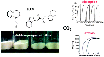
Hydroxyalkyl amidine (HAM) derivatives react with CO2 in a quantitative manner under dry conditions near room temperature, and then release it at a moderate temperature of approximately 60 °C. In the present study, HAM compounds were impregnated into porous silica particles to obtain solid CO2 sorbents. This process produced a large surface area for reaction between CO2 and the absorbents for enhanced CO2 capture efficiency. Several types of mesoporous silicas that differed in pore size, pore volume, and particle size and shape were investigated in order to identify the optimum processing parameters for preparation of hybrid materials with the best possible CO2 capture performance. The amount of HAMs loaded into the silica was optimized so as to retain the open porous structure for efficient transport of gas molecules, while providing a large surface area of reactive material. We have demonstrated that HAM-loaded silica could be used as an effective CO2 filter for dilute gas mixtures such as air.
Introduction
Effective energy efficient and environmentally friendly materials for CO2 capture are highly sought after for use in a number of applications. They can be employed to remove CO2 as an impurity from valuable product gases, and can aid in its recovery as a saleable product from processes such as ethanol production. Another important use of these materials is to sequester the gas to prevent it from being released into the atmosphere.1 Numerous liquid and solid materials, including amines,2,3 ionic liquids, activated carbon,4–6 metallic oxides,7–9 superbases,10–14 metal–organic frameworks,15–18 and porous organic networks,19–22 have been developed for use in CO2 capture applications.
Solid state capture and regeneration based on dry absorbents is a promising approach that meets the energy and environmental requirements of the carbon capture process. In particular, solid CO2-capturing materials may be suitable for ‘air capture’, which could be complementary to flue-gas capture technology, working under ambient conditions with very low concentrations of CO2.23,24 These materials may also be useful for applications involving the maintenance of indoor CO2 concentrations below the level at which hazardous health effects may result.
One of the most promising materials in this regard consists of solid-supported amine absorbents, in which the amines are physically impregnated into, or chemically grafted onto, porous solids.25–28 Jones et al. divided these materials into three classes according to how the amine compounds are bound inside the pores.29 Type II and III absorbents, where the amines are covalently bound inside porous solid supports, have shown promising performances. However, type I absorbents, which are prepared by simple impregnation of the chemical absorbents into the porous support, remain of interest because they have advantages in terms of material costs, scale-up possibility, and the wide variety of possible combinations of absorbents and supports. Different types of porous materials have been employed as supports for amine impregnation,30–32 among which porous silica is the most commonly studied. Song et al. reported the concept of a molecular basket consisting of MCM-41 impregnated with polyethyleneimine (PEI).33,34 Other support materials have also been shown to exhibit enhanced capture efficiency.35–37 Appropriate morphological structures and pore chemistry of solid supports are required for efficient loading of organic absorbents. Various types of mesoporous silica, differing in the pore morphology, have been tested for CO2 capture under different conditions.38–41 The chemical nature of the pore surface is an important factor that needs to be considered when attempting to achieve uniform dispersion of the absorbents. Pore-expanded MCM-41, whose surface is covered with an alkyl chain layer, was reported to enhance the dispersion of PEI.42,43 Additives to help dispersion of amines within the pores, or to enhance the capture capacity, have also been assessed.44–47
The selection of an organic absorbent that does not evaporate or decompose under the capture/release conditions is critical for maintaining the CO2 capture efficiency of solid-supported absorbents. PEI has been frequently used for impregnation owing to its low volatility, giving reproducible capture and regeneration performance.48,49 Despite the advantages, the loss of capture efficiency caused by the urea-forming side reaction between amines and CO2 under dry conditions at a regeneration temperature above 100 °C is a potential problem.50 Therefore, the development of alternative organic absorbents that can operate under milder conditions than those required for PEI is highly desirable. This is of particular importance for materials to be used for air capture or indoor CO2 control.
Apart from PEI, only a limited number of organic absorbents have been employed for preparation of impregnated CO2 capture materials. In a previous study, we demonstrated that hydroxyalkyl amidine (HAM) derivatives are promising candidates for preparation of solid absorbents. They are able to capture CO2 and regenerate quantitatively by varying the temperature between ambient and 60 °C.14 HAMs impregnated into a silica gel exhibited enhanced performance and cycle stability in comparison to when used as neat organic compounds. Although the HAMs had smaller molar masses than PEI, they appeared to be stable when adsorbed within the pores of the supports under the mild CO2 capture and regeneration conditions required. This may be partly explained by the fact that the silanol groups of the silica surface can bind with the superbases via H-bonding or electrostatic interactions.
To achieve high CO2 capture by HAM-impregnated silica, the morphological structures of the support material, and the specific composition of the HAM and silica combination, need to be optimized. If the absorbent loading is too high, the pores of the silica support would be completely filled, resulting in decreased delivery of CO2 to the absorbent molecules. Critical loadings of absorbents for different types of silica should therefore be derived so that maximum capture efficiency per unit weight of the absorbent can be accomplished.
Here, we set out to optimize such parameters by studying the effect of the morphological structure of mesoporous silica and the amount of HAM loaded onto each silica type on the CO2 capture performance of the resulting HAM-impregnated silica (HIMS) absorbents. Five different silica supports were evaluated, including three types of silica gel (SG1, SG2, and SG3), MCM-41, and SBA15, which differ in pore size and arrangement, and powder particle size and shape. The morphological changes in the HIMS that occurred with increasing HAM loading were characterized using X-ray diffraction (XRD), thermogravimetric analysis (TGA), and gas adsorption isotherm measurement. We fabricated a CO2 filtration kit that could be operated reversibly for CO2 capture from gas mixtures with low CO2 concentration. This study presents the preparation of new organic/inorganic hybrid CO2 absorbents. It also demonstrates that the performance of these material combinations could be maximized by appropriate choice of the organic and inorganic components, providing control over absorbent loading and pore morphologies.
Results and discussion
Preparation of HAM-impregnated mesoporous silica (HIMS)
Two HAMs, DBUOH and (DBNOH)2, were used for impregnation into the silica supports (Fig. 1). These were synthesized via lithiation of 1.8-diazabicyclo[5.4.0]undec-7-ene (DBU) and 1,5-diazabicyclo[4.3.0]non-5-ene (DBN), followed by reaction with ethylene oxide and 1,3-butadiene diepoxide, respectively, as reported previously. DBUOH and (DBNOH)2 differ in their molar mass (monomeric or dimeric) and phase state (liquid or solid at r.t.), which may affect their impregnation into silica, in addition to their CO2 capture efficiency. The HAMs were impregnated into each of silica types listed in Table 1, which differ in terms of pore diameter, and particle shape and size. The silica particles were added into a THF solution of the corresponding HAM compound, and the mixture was evaporated and dried under reduced pressure. As long as the HAM loading was kept below 60%, the resulting HIMS samples were obtained as dry powders.
 |
| Fig. 1 Structure of the two HAMs investigated in this study. | |
Table 1 Characteristics of mesoporous silica used for impregnation of HAMs
Silica type |
Average pore diameter (nm) |
Pore volume (cm3 g−1) |
Specific surface area (m2 g−1) |
Particle size (μm) |
SG1 |
6.0 |
0.74–0.84 |
∼500 |
200–500 |
SG2 |
15.0 |
1.15 |
300 |
35–70 |
SG3 |
15.0 |
1.15 |
300 |
250–500 |
MCM-41 |
2.6 |
1.08 |
980 |
0.5–1 |
SBA15 |
3.8 |
0.56 |
670 |
1–5 |
The compositions of the prepared dry HIMS powders were confirmed using TGA. Fig. 2 shows a typical set of TGA curves obtained from SG2 containing different amounts of DBUOH. Residual weight percentages above 450 °C almost corresponded to the weight fraction of silica in each of the HIMS mixtures, indicating that the loss of HAM during drying under reduced pressure was negligible. The TGA curves indicate that the HAM compounds started to evaporate from the mixture at temperatures close to 150 °C under a constant flow of N2, which is much greater than the decarboxylation temperature (∼60 °C) of the carbonate salt of the HAMs.
 |
| Fig. 2 TGA curves of pure SG2 and HAM-impregnated SG2 containing 20, 30, 40, and 50% DBUOH, and pure DBUOH. Heating rate of 10 °C min−1 under a N2 flow of 20 mL min−1. | |
Porosity of the mesoporous silica impregnated with HAMs
The morphologies and porosities were found to change on adsorption of organic substances onto the silica surface. For efficient CO2 absorption by the HIMS, it would be ideal to produce a morphology consisting of the HAM compound uniformly coated onto the pore surface. In order to evaluate this, the change in the pore characteristics was characterized by measuring N2 adsorption isotherms. Fig. 3 shows the adsorption isotherm and pore size distribution curves obtained for the DBUOH/SG2 HIMS. All of the sorbents showed type IV isotherms. In Fig. 4 the specific BET surface area (SBET), pore volume (Vp), and peak pore diameter (Dp), which varied with the loading of DBUOH and (DBNOH)2, are given. Uniform coating of the absorbent molecules onto the pore surface would give decreases in Dp, SBET, and Vp with increasing HAM loading. Careful examination of the data in Fig. 3 and 4 revealed that the SBET and Vp decreased proportionally with increased HAM loading, whereas Dp tended to stay within a range, regardless of the loading. This result suggests that the pore surface was uniformly coated with the adsorbed HAM molecular layer, with the smaller pores becoming filled with the HAM and the larger pores being reduced in size by the thickening film on increasing the HAM loading. The slight increase in pore diameter that was observed when the loading exceeded 30% may correspond to the loss of small pores becoming increasingly significant after complete filling with the HAM molecules. At loadings above 50%, no porosity was observed, indicative of complete filling of the pores.
 |
| Fig. 3 (a) N2 adsorption isotherms and (b) pore size distributions obtained for SG2 with DBUOH contents of none, 20, 30, 40, and 50%. | |
 |
| Fig. 4 Specific surface area (a), pore volume (b), and pore diameter (c) of HAM-loaded SG2 as a function of HAM loading: triangles, DBUOH; squares, (DBNOH)2. | |
CO2 adsorption isotherms were also acquired for the DBUOH/SG2 samples with different DBUOH loadings. As can be seen in Fig. 5a, an abrupt jump in the amount of adsorbed CO2 occurred as soon as the CO2 pressure started to increase. This was attributed to rapid chemical absorption by the DBUOH molecules in the surface layer on the silica as the isotherm curves obtained after evacuation of the cell at the same temperature did not show the initial absorption jump (Fig. 5b), and the sample released CO2 only when heated (Fig. 5c). The initial uptake was reduced in the samples with DBUOH loading of 60%, showing that the transport of CO2 through completely-filled pores was sluggish, retarding the carbonation reaction with DBUOH.
 |
| Fig. 5 (a) CO2 adsorption isotherms of DBUOH/SG2 with different loadings of DBUOH, measured at 298 K, (b) isotherm curves obtained from two consecutive CO2 adsorption–desorption cycles with a DBUOH30/SG2 sample after initial activation by heating to 110 °C under vacuum, and (c) TGA curve of the sample after final desorption 2 of (b). | |
XRD analysis of HIMS of MCM-41 or SBA15, which had ordered pore structures, provided further evidence of the pore filling trends. Fig. 6 shows the XRD spectra of DBUOH/MCM-41 with different DBUOH loadings. The MCM-41 material had hexagonally ordered cylindrical pores, which gave sharp scattering peaks corresponding to the (100), (110), (200), and (210) planes. On increasing the DBUOH loading, the intensity of the scattering peaks decreased, which was indicative of the reduction in X-ray contrast as the organic compounds filled the empty pores. The XRD peak positions remained the same for all samples. Although this result was expected as the ordered mesoporous structure was preserved regardless of the degree of impregnation, the observed gradual decrease in the peak intensity may be considered as an indication of uniform impregnation of the organic absorbents into the nanopores.
 |
| Fig. 6 XRD curves of DBUOH-impregnated MCM-41 with different loadings of DBUOH: (a) 0, (b) 20, (c) 30, (d) 40, and (e) 50%. | |
CO2 capture by HIMS with various amounts of HAM
The obtained porosity measurements for the HIMS demonstrated complete filling of the pores with the organic absorbents above a certain critical loading, which may inhibit CO2 molecules from accessing the deep pores and thus reduce molar capture efficiency of the HAMs. Therefore, we sought to identify the optimum loading of HAM for each type of silica in order to achieve maximum CO2 capture. TGA was used to obtain CO2 absorption profiles for each of the HIMS mixtures, differing in the type of HAM and mesoporous silica employed and the mixture composition. The change in sample weight was monitored under a flow of CO2 at 20 mL min−1 at 25 °C (Fig. 7). The molar capture efficiency (mol CO2/mol HAM) and the capture capacity (mg CO2/g HIMS) for each of the HIMS were plotted against the % weight fraction (WH) of the corresponding HAM (Fig. 8).
 |
| Fig. 7 Isothermal TGA curves of (a) DBUOH/SG2 and (b) DBUOH/MCM-41, respectively, at 25 °C under a CO2 flow of 20 mL min−1 as a function of the wt% of DBUOH. | |
 |
| Fig. 8 The change in capture capacity (in mg CO2/g HIMS) and efficiency (in mol CO2/mol HAM) as a function of the weight fraction (WH in %) of DBUOH and (DBNOH)2 in SG2, MCM-41, and SBA15, respectively: (a) DBUOH/SG2; (b) (DBNOH)2/SG2; (c) DBUOH/MCM-41; (d) (DBNOH)2/MCM-41; (e) DBUOH/SBA15; (f) (DBNOH)2/SBA15. | |
In the data shown in Fig. 7 and 8, the dependence of the molar capture efficiency on the HAM loading can be seen to vary with different combinations of HAM and silica. In general, the molar capture efficiency approached 0.8–1.0 in the range of low loading, and decreased as the HAM loading was increased above an optimum range.
Approximate values for the optimum loading of DBUOH for the five silica types were estimated from the data shown in Fig. 7 and 8, and S1, ESI.† The optimum loading of DBUOH appeared to be in the range of 30–40% for the SG2, SG3, and MCM-41, while it appeared to be lower than this for the SG1, and higher for the SBA15. The pores of SG1 were likely blocked even at a low HAM loading because it had narrower pores within larger particles in comparison with the other silicas. Small particles seemed to be advantageous for efficient CO2 capture, as observed for DBUOH in SBA15, where high capture efficiency was obtained for loadings as high as 60%, despite the small pores. It is likely that well-arranged pores within small particles facilitated the transport and adsorption of the absorbent into the pores as well as the diffusion of CO2 molecules.
(DBNOH)2, which is a dimeric HAM and crystalline solid at r.t., was also impregnated into the five silica supports. In contrast to the liquid DBUOH, (DBNOH)2 in its as-prepared neat powdery form usually exhibits a CO2 capture efficiency below 0.1, most likely due to the difficulty of CO2 diffusion through the absorbent. Impregnation of this compound into the nanoporous supports investigated in the present study enhanced the capture efficiency to almost 0.8. It is evident that dispersion of the solid compound on the nanopore surface facilitated the CO2-binding reaction with (DBNOH)2.
The dependence of the capture efficiency of (DBNOH)2 on its loading in the five silica types appeared different from that observed with DBUOH. In general, the capture efficiencies of (DBNOH)2 in MCM-41 and SBA15, were much lower than those for SG2 and SG3. In particular, (DBNOH)2 in SBA15 gave the poorest molar efficiency, with the maximum efficiency only about 0.4 at 30% loading. This is in a sharp contrast to the DBUOH/SBA15, which exhibited an efficiency close to 1.0 at a loading as high as 60%. This result is accounted for by the different molecular sizes of the two HAMs, which would affect the extent of dispersion into the small pores of the substrate during the solution-based impregnation process. The pore diameters of MCM-41 and SBA15 were 2.7 and 4.6 nm, respectively, and were almost mono-dispersed. In contrast, the silica gels (SG2 and SG3) contained pores with a wide range of sizes, and an average value of 15 nm. As the impregnation process consisted of simple mixing and solvent evaporation, transport of (DBNOH)2 through the narrow pores of MCM-41 and SBA15 would be much more difficult than through the wider pores of SG2 and SG3. Any absorbent that did not enter the pores would have been deposited as crystalline powder on the exterior of the particles, reducing the available HAM surface area for CO2 capture.
After repeated TGA of CO2 capture involving the two HAM compounds dispersed in the five silica types, it was concluded that the two amorphous silica gels (SG2 and SG3), which had moderate porosities with a broad range of pore sizes, were the most efficient host materials for both HAM compounds. The ordered mesoporous materials, MCM-41 and SBA15, exhibited good results for the DBUOH HAM only.
The recyclability of the HIMS was examined by five consecutive CO2 capture–release runs in the TGA, as shown in Fig. 9. The silica materials containing DBUOH in a quantity greater than 40% exhibited a loss of capture capacity over multiple cycles (Fig. 10), likely caused by evaporation of the excess absorbent deposited outside of the pores. In contrast, dimeric HAM, (DBNOH)2, exhibited no loss even at a higher loading, reflecting its lower volatility. Nevertheless, an optimal amount of absorbent loading is essential for minimizing absorbent loss while maximizing the capture efficiency.
 |
| Fig. 9 CO2 capture capacity (in mg CO2/g HIMS) TGA curves for five consecutive capture–release cycles for (a) DBUOH 20% in SG2, (b) DBUOH 40% in SG 3, (c) DBUOH 60% in SBA15, and (DBNOH)2 50% in SG3. Capture was conducted under a CO2 flow of 20 mL min−1 at 25 °C for 150 min. Regeneration was carried out by heating at 65 °C under a N2 flow of 20 mL min−1. | |
 |
| Fig. 10 Capture capacity as a function of cycle number: (a) DBUOH 20% in SG2, (b) DBUOH 50% in SG2, (c) (DBNOH)2 50% in SG3, (d) DBUOH 40% in SG2, and (e) DBUOH 60% in SBA15. | |
Absorption and desorption time were about 2 h and 10 min, respectively, in the TGA runs shown in Fig. 9. Long absorption time may be reduced by setting the capacity target slightly lower than saturation point.
It is noteworthy that CO2 capture and release by HAMs are based on formation and decomposition of alkylcarbonates under anhydrous conditions, not the bicarbonate that could form in the presence of moisture. CO2 release can begin as low as 65 °C in anhydrous conditions, however true regeneration temperatures under simulated conditions have not yet been finalized.
Fabrication of a CO2 absorption filter and breakthrough testing
We fabricated a CO2 absorption filter using a DBUOH/SG2 combination, and then evaluated its ability for absorption of CO2 from a low concentration source. A stainless steel column filled with DBUOH/SG2 was jacketed with heating tape connected to a thermocouple (Fig. S2, ESI†). Breakthrough curves were recorded on a CO2 sensor placed at the outlet of the column. Fig. 11 and 12 show that the HAM-loaded SG2 particles efficiently absorbed CO2 from dilute gas mixtures. The capture efficiency of the filter decreased with increasing flow rate of the feed gas, as indicated by the breakthrough curve where the CO2 concentration at the exiting gas was plotted against the retention volume of the feed gas at different flow rates (Fig. 12b and c). The filter exhibited nearly identical breakthrough curves on multiple capture runs after regeneration (Fig. 12d). Although the data in Fig. 11 and 12 demonstrate that the HIMS materials may be utilized for the capture of CO2 from a gas mixture containing a low concentration of the molecule, the dependence of the capture efficiency on the flow rate suggests that a reactor with an architecture that would maximize the gas-absorbent contact at a higher flow rate would be required for enhancement of dry CO2 capture efficiency.
 |
| Fig. 11 Breakthrough curves for each of the filters filled with different HIMS with the same amount of DBUOH (40 wt%). A gas mixture of N2 with 1800 ppm CO2 was passed through the filter at a rate of 100 mL min−1 at room temperature. | |
 |
| Fig. 12 Breakthrough curves with a filter filled with DBUOH/SG2 powder. (a) curves for different DBUOH loadings, (b) curves for DBUOH 40/SG2 with varying flow rate of the 1800 ppm CO2 feed gas, (c) curves for DBUOH 40/SG2 plotted against retention volume at flow rates of 100 and 20 mL min−1, respectively, and (d) curves obtained by four consecutive cycles of absorption–regeneration. After absorption was performed at 25 °C for 4000 s, the filter was heated to 70 °C for a period of 4000 s with a flow of N2 at 100 mL min−1. | |
Experimental section
Materials
1.8-Diazabicyclo[5.4.0]undec-7-ene (DBU, 98%, Sigma-Aldrich) and 1,5-diazabicyclo[4.3.0]non-5-ene (DBN, TCI) were refluxed over CaH2 and distilled under vacuum in the presence of 4 Å molecular sieves before use. n-BuLi (1.6 M in hexane) was used as received. Ethylene oxide (99.5%, Sigma-Aldrich) and 1,3-butadiene diepoxide (TCI) were dissolved in dry THF before use. The THF was first distilled using Na and benzophenone. Tetraethylorthosilicate (TEOS), cetyltrimethyl ammonium bromide (CTAB), and Pluronic P123 were all obtained from Sigma-Aldrich, and were used as received. HCl (37%) and NH3 solution (25%) were obtained from Sigma-Aldrich. Three different commercially available amorphous silicas were used: SG1 (Merck), SG2 (Sigma-Aldrich), and SG3 Sigma-Aldrich. Their specific surface areas, particle sizes, and pore sizes are given in Table 1. The silicas were all baked at 150 °C under reduced pressure to remove adsorbed moisture before impregnation of the amidine compounds. CO2 (99.95%), air containing 1800 ppm CO2, and N2 (99.95%) were dried by passing through a CaSO4 column prior to the capture experiments. DBUOH and (DBNOH)2 were synthesized by following the procedure reported previously.14
Synthesis of mesoporous silica
MCM-41 was synthesized as follows: 25 wt% NH4OH solution (205 mL) was added to DI H2O (270 mL) at room temperature. CTAB (2 g) was dissolved in the resulting solution and heated at 80 °C, giving a homogeneous solution after stirring for 2 h. TEOS (10 mL) was then added, resulting in the formation of a white slurry. After 2 h, the mixture was washed with DI H2O and filtered. After drying at room temperature overnight, calcination was conducted in air at 550 °C for 4 h.51
SBA15 was prepared using the tri-block copolymer, Pluronic P123 (EO20-PO70-EO20), as a template. HCl solution (2 M, 120 g) was added to DI water (30 g) at 35 °C. Pluronic P123 (4 g) was then added to the solution with stirring. TEOS (10 mL) was subsequently added, and the mixture was left to stir for 20 h. The resulting white mixture was aged at 80 °C overnight without stirring. The product was filtered, washed with DI water, and dried in air. Calcination was carried out by slowly increasing the temperature from room temperature to 500 °C over 8 h and then holding it at 500 °C for 6 h.52
Impregnation of HAMs into silica
In a typical preparation, the HAM compound was dissolved in dry THF with stirring. This mixture was then added to dry silica and stirred under a N2 atmosphere for 2 h. The mixture was evaporated under reduced pressure (0.01 mm Hg) for 1 day. The resulting solid sorbents were denoted as DBUOH-X/MCM-41, (DBNOH)2-X/MCM-41, where X is the weight percentage of the corresponding HAM in the sample. The three different commercially available amorphous silicas, and the above synthesized MCM-41 and SBA15 were used as the supports for impregnation.
Characterization
Powder XRD patterns were recorded on a Rigaku RINT 2000 diffractometer with Cu-Kα radiation (λ = 1.54 Å). N2 adsorption–desorption isotherms were obtained on a Micrometrics ASAP 2020 volumetric adsorption analyzer at 77 K. The samples were degassed at 110 °C for 4 h under high vacuum prior to measurement. The specific surface areas (SBET) were determined from the linear part of the Brunauer–Emmett–Teller (BET) equation. The pore volumes of the dry solid sorbents were calculated from the adsorbed N2 after complete pore condensation (P/P0 = 0.995) using the ratio of the densities of liquid and gaseous N2. The amounts of DBUOH impregnated into the silica supports were confirmed using TGA (TA instrument 2100 series). The sample (10 mg) was heated at a rate of 10 °C min−1 to 800 °C under a flow of N2 (20 mL min−1).
CO2 absorption and release measurements
TGA: CO2 capture and release measurements were performed using TGA. First, the dry sample (10 mg) was loaded into a TGA ceramic pan and baked at 110 °C for 5 min under a N2 atmosphere. After cooling to 25 °C, CO2 capture was conducted using a flow of CO2 at 20 mL min−1 at 25 °C for 150 min. Regeneration was carried out by heating at 6 5 °C under N2 flow at 20 mL min−1.
Breakthrough test: dry absorbent (0.5 g) was loaded into a home-made test cell (figure). A CO2 sensor was placed at the outlet of the cell. Prior to capture measurements, the sorbent was heated to 100 °C to eliminate any absorbed CO2 or moisture. For the capture test, air containing 1800 ppm CO2 was passed through at 25 °C. Regeneration was carried out by heating at 7 5 °C under a flow of N2 at 100 mL min−1.
Conclusions
We studied the preparation of solid CO2 absorbents by combining HAM derivatives and mesoporous silica. Two HAM compounds, DBUOH and (DBNOH)2, were separately impregnated into five different mesoporous silica materials with different particle sizes and porosities. An optimum loading of the organic absorbent of 30–40 wt% was needed for sufficient dispersion of the absorbent molecules into the mesopores, and to enhance the CO2 capture efficiency, and stability of the absorbents. The HAM-impregnated mesoporous silica was demonstrated to be able to capture CO2 from a gas mixture with a dilute concentration of CO2. This study presents a simple route to the preparation of new organic/inorganic hybrid CO2 absorbents, emphasizing the importance of optimizing both the support and absorbent materials to achieve maximum capture efficiency.
Acknowledgements
This work was supported by the Korea CCS R&D Center (KCRC) grant funded by the Korean government (Ministry of Science, ICT & Future Planning) (NRF-2011-0031794).
Notes and references
- A. D. Ebner and J. A. Ritter, Sep. Sci. Technol., 2009, 44, 1273–1421 CrossRef CAS.
- G. T. Rochelle, Science, 2009, 325, 1652–1654 CrossRef CAS PubMed.
- J. T. Yeh, H. W. Pennline and K. P. Resnik, Energy Fuels, 2001, 15, 274–278 CrossRef CAS.
- N. Hedin, L. Chen and A. Laaksonen, Nanoscale, 2010, 2, 1819–1841 RSC.
- S. Sircar, T. C. Golden and M. B. Rao, Carbon, 1996, 34, 1–12 CrossRef CAS.
- R. V. Siriwardane, M.-S. Shen, E. P. Fisher and J. A. Poston, Energy Fuels, 2001, 15, 279–284 CrossRef CAS.
- H. Hayashi, J. Taniuchi, N. Furuyashiki, S. Sugiyama, S. Hirano, N. Shigemoto and T. Nonaka, Ind. Eng. Chem. Res., 1998, 37, 185–191 CrossRef CAS.
- Y. Liang, D. P. Harrison, R. P. Gupta, D. A. Green and W. J. McMichael, Energy Fuels, 2004, 18, 569–575 CrossRef CAS.
- C. K. Yi, S. H. Jo, Y. Seo, J. B. Lee and C. K. Ryu, Int. J. Greenhouse Gas Control, 2007, 1, 31–36 CrossRef CAS.
- D. J. Heldebrant, P. G. Jessop, C. A. Thomas, C. A. Eckert and C. L. Liotta, J. Org. Chem., 2005, 70, 5335–5338 CrossRef CAS PubMed.
- D. J. Heldebrant, C. R. Yonker, P. G. Jessop and L. Phan, Energy Environ. Sci., 2008, 1, 487–493 CAS.
- P. K. Koech, J. Zhang, I. V. Kutnyakov, L. Cosimbescu, S.-J. Lee, M. E. Bowden, T. D. Smurthwaite and D. J. Heldebrant, RSC Adv., 2013, 3, 566–572 RSC.
- L. Phan, D. Chiu, D. J. Heldebrant, H. Huttenhower, E. John, X. Li, P. Pollet, R. Wang, C. A. Eckert, C. L. Liotta and P. G. Jessop, Ind. Eng. Chem. Res., 2007, 47, 539–545 CrossRef.
- M. Kim and J.-W. Park, Chem. Commun., 2010, 46, 2507–2509 RSC.
- H.-S. Choi and M. P. Suh, Angew. Chem., Int. Ed., 2009, 48, 6865–6869 CrossRef CAS PubMed.
- P. D. C. Dietzel, V. Besikiotis and R. Blom, J. Mater. Chem., 2009, 19, 7362–7370 RSC.
- J. Klinowski, F. A. Almeida Paz, P. Silva and J. Rocha, Dalton Trans., 2011, 40, 321–330 RSC.
- K. Nakagawa, D. Tanaka, S. Horike, S. Shimomura, M. Higuchi and S. Kitagawa, Chem. Commun., 2010, 46, 4258–4260 RSC.
- M. G. Rabbani and H. M. El-Kaderi, Chem. Mater., 2012, 24, 1511–1517 CrossRef CAS.
- Q. Chen, M. Luo, P. Hammershøj, D. Zhou, Y. Han, B. W. Laursen, C.-G. Yan and B.-H. Han, J. Am. Chem. Soc., 2012, 134, 6084–6087 CrossRef CAS PubMed.
- B. Li, R. Gong, W. Wang, X. Huang, W. Zhang, H. Li, C. Hu and B. Tan, Macromolecules, 2011, 44, 2410–2414 CrossRef CAS.
- R. Dawson, E. Stockel, J. R. Holst, D. J. Adams and A. I. Cooper, Energy Environ. Sci., 2011, 4, 4239–4245 CAS.
- C. W. Jones, Ann. Rev. Chem. Biomol., 2011, 2, 31–52 CrossRef CAS PubMed.
- S. A. Didas, A. R. Kulkarni, D. S. Sholl and C. W. Jones, ChemSusChem, 2012, 5, 2058–2064 CrossRef CAS PubMed.
- S. Choi, J. H. Drese, P. M. Eisenberger and C. W. Jones, Environ. Sci. Tech., 2011, 45, 2420–2427 CrossRef CAS PubMed.
- N. Hiyoshi, K. Yogo and T. Yashima, Chem. Lett., 2004, 33, 510–511 CrossRef CAS.
- Z. Liang, B. Fadhel, C. J. Schneider and A. L. Chaffee, Microporous Mesoporous Mater., 2008, 111, 536–543 CrossRef CAS PubMed.
- E. J. Acosta, C. S. Carr, E. E. Simanek and D. F. Shantz, Adv. Mater., 2004, 16, 985–989 CrossRef CAS.
- W. Li, S. Choi, J. H. Drese, M. Hornbostel, G. Krishnan, P. M. Eisenberger and C. W. Jones, ChemSusChem, 2010, 3, 899–903 CrossRef CAS PubMed.
- W. R. Alesi, M. Gray and J. R. Kitchin, ChemSusChem, 2010, 3, 948–956 CrossRef CAS PubMed.
- W. Chaikittisilp, H.-J. Kim and C. W. Jones, Energy Fuels, 2011, 25, 5528–5537 CrossRef CAS.
- M. L. Gray, K. J. Champagne, D. Fauth, J. P. Baltrus and H. Pennline, Int. J. Greenhouse Gas Control, 2008, 2, 3–8 CrossRef CAS.
- X. Xu, C. Song, J. M. Andrésen, B. G. Miller and A. W. Scaroni, Microporous Mesoporous Mater., 2003, 62, 29–45 CrossRef CAS.
- X. Xu, C. Song, J. M. Andresen, B. G. Miller and A. W. Scaroni, Energy Fuels, 2002, 16, 1463–1469 CrossRef CAS.
- A. Heydari-Gorji, Y. Yang and A. Sayari, Energy Fuels, 2011, 25, 4206–4210 CrossRef CAS.
- Y. Kuwahara, D.-Y. Kang, J. R. Copeland, N. A. Brunelli, S. A. Didas, P. Bollini, C. Sievers, T. Kamegawa, H. Yamashita and C. W. Jones, J. Am. Chem. Soc., 2012, 134, 10757–10760 CrossRef CAS PubMed.
- Y. Liu, J. Shi, J. Chen, Q. Ye, H. Pan, Z. Shao and Y. Shi, Microporous Mesoporous Mater., 2010, 134, 16–21 CrossRef CAS PubMed.
- W. J. Son, J. S. Choi and W. S. Ahn, Microporous Mesoporous Mater., 2008, 113, 31–40 CrossRef CAS PubMed.
- A. Goeppert, M. Czaun, R. B. May, G. K. S. Prakash, G. A. Olah and S. R. Narayanan, J. Am. Chem. Soc., 2011, 133, 20164–20167 CrossRef CAS PubMed.
- C. Chen, S.-T. Yang, W.-S. Ahn and R. Ryoo, Chem. Commun., 2009, 3627–3629 RSC.
- G. Qi, Y. Wang, L. Estevez, X. Duan, N. Anako, A.-H. A. Park, W. Li, C. W. Jones and E. P. Giannelis, Energy Environ. Sci., 2011, 4, 444–452 CAS.
- A. Heydari-Gorji, Y. Belmabkhout and A. Sayari, Langmuir, 2011, 27, 12411–12416 CrossRef CAS PubMed.
- M. B. Yue, Y. Chun, Y. Cao, X. Dong and J. H. Zhu, Adv. Funct. Mater., 2006, 16, 1717–1722 CrossRef CAS.
-
A. L. Kohl and R. B. Nielsen, Gas Purification, Elsevier, 1997 Search PubMed.
- S. Meth, A. Goeppert, G. K. S. Prakash and G. A. Olah, Energy Fuels, 2012, 26, 3082–3090 CrossRef CAS.
- M. Anbia, V. Hoseini and S. Mandegarzad, Korean J. Chem. Eng., 2012, 29, 1776–1781 CrossRef CAS PubMed.
- D. J. Fauth, M. L. Gray, H. W. Pennline, H. M. Krutka, S. Sjostrom and A. M. Ault, Energy Fuels, 2012, 26, 2483–2496 CrossRef CAS.
-
P. K. Gregory, A. W. Paul, L. Zhijian and L. C. Alan, in ACS Symp. Ser., American Chemical Society, 2012, vol. 1097, ch. 9, pp. 177–205 Search PubMed.
- A. Goeppert, S. Meth, G. K. S. Prakash and G. A. Olah, Energy Environ. Sci., 2010, 3, 1949–1960 CAS.
- A. Sayari, A. Heydari-Gorji and Y. Yang, J. Am. Chem. Soc., 2012, 134, 13834–13842 CrossRef CAS PubMed.
- Q. Cai, W. Y. Lin, F. S. Xiao, W. Q. Pang, X. H. Chen and B. S. Zou, Microporous Mesoporous Mater., 1999, 32, 1–15 CrossRef CAS.
- D. Zhao, Q. Huo, J. Feng, B. F. Chmelka and G. D. Stucky, J. Am. Chem. Soc., 1998, 120, 6024–6036 CrossRef CAS.
Footnote |
† Electronic supplementary information (ESI) available: TGA CO2 absorption curves of HIMS samples, a photograph of CO2 absorption filter. See DOI: 10.1039/c3ra45063e |
|
This journal is © The Royal Society of Chemistry 2014 |
Click here to see how this site uses Cookies. View our privacy policy here.