Spinel materials for high-voltage cathodes in Li-ion batteries
D.
Liu
a,
W.
Zhu
a,
J.
Trottier
a,
C.
Gagnon
a,
F.
Barray
a,
A.
Guerfi
a,
A.
Mauger
b,
H.
Groult
b,
C. M.
Julien
c,
J. B.
Goodenough
d and
K.
Zaghib
*a
aEnergy Storage and Conversion, Research Institute of Hydro-Québec, 1800 Bd Lionel-Boulet, Varennes, Québec J3X 1S1, Canada. E-mail: karim.zaghib@ireq.ca
bUniversité Pierre et Marie Curie – Paris6, Institut de Minéralogie et Physique de la Matière Condensée (IMPMC), 4 place Jussieu, 75005 Paris, France
cUniversité Pierre et Marie Curie – Paris6, Physicochimie des Electrolytes, Colloïdes et Sciences Analytiques (PECSA), 4 place Jussieu, 75005 Paris, France
dThe University of Texas at Austin, 1 University Station C2220, Austin, USA
First published on 6th November 2013
Abstract
The success of lithium-ion batteries in small-scale applications translates to large-scale applications, with an important impact in the future of the environment by improving energy efficiency and reduction of pollution. In this review, we present the progress that allows lithium-insertion compounds with the spinel structure to become the active cathode element of a new generation of Li-ion batteries, namely the 5 V cathodes, which promise to improve the technologies of energy storage and electric transportation, thereby addressing the replacement of the gasoline engine and the increasing demand for green energy power sources. The compounds considered here include the spinel LiNi0.5Mn1.5O4 and its related Cr-doped structure. Emphasis is placed on the control of physical properties that is needed to guarantee the reliability and the optimum electrochemical performance of these materials as the active cathode element of Li-ion batteries. We also report the structural evolution of the spinel phase in both charge (Li extraction) and discharge (Li insertion) reactions.
A Introduction
Developing cathode materials with high energy densities is one of the key challenges for adopting the lithium-ion battery technology for the hybrid electric vehicle (HEV) and the plug-in hybrid electric vehicle (PHEV) applications. A high energy density can be obtained either by high voltage or high capacity.1–3 With a high operating voltage around 4.7 V and a practical capacity (about 130 mA h g−1) comparable to that of LiCoO2 (∼140 mA h g−1) and LiFePO4 (∼160 mA h g−1), spinel LiNi0.5Mn1.5O4 provides a specific energy (∼610 W h kg−1) higher than that of many commercialized compounds. Since the demonstration of lithium intercalation–deintercalation reversibility in LiMn2O4,4 mixed lithium transition-metal oxides with spinel structure have been considered as possible candidates for cathode materials in lithium ion secondary batteries.5 The interstitial space of the spinel framework provides 3D channels for high-rate Li+ conduction. Moreover, the Mn4+ of the LiNi0.5Mn1.5O4 spinel, herein after named LNM, lowers both the Ni3+/Ni2+ couple to 4.7 V and the top of the O-2p bands to 4.8 V versus Li to provide a high voltage cathode that operates on both the Ni3+/Ni2+ and Ni4+/Ni3+ couples with no significant voltage step between them. Following the early work of Amine et al.,8 LNM and related compounds have attracted considerable attention from many research groups in the field of energy storage; more than 300 papers have been published so far,6–77 and this number increases rapidly.Terada et al.15 revealed that the plateau at around 4.7 V is due to the Ni2+/Ni4+ redox, whereas a small plateau at 4.1 V arises from the Mn3+/Mn4+ redox couple, as observed by in situ X-ray absorption fine-structure spectroscopy (XAFS) analysis for the Li1−xNi0.31Mn1.69O4 material. For the ideal LiNi0.52+Mn1.54+O4 composition, i.e. in the absence of any deviation from stoichiometry, the oxidation state of Mn should be fixed at +4, resulting in only the Ni2+/Ni4+ redox couple during the charge–discharge process. The access to two nickel redox couples, Ni3+/Ni2+ and Ni4+/Ni3+, at ∼4.7 eV below the Fermi energy of a lithium metal anode with a negligible voltage step between the two couples leads to a theoretical gravimetric capacity of 146.7 mA h g−1. At high potential, LNM delivers an energy density equivalent to ∼650 W h kg−1 of active material. This value is the highest among commercially available cathode materials such as LiCoO2 (518 W h kg−1), LiMn2O4 (400 W h kg−1), LiFePO4 (495 W h kg−1) and LiCo1/3Ni1/3Mn1/3O2 (576 W h kg−1). Advantages and drawbacks of LiNi0.5Mn1.5O4 have been pointed out: this cathode material includes inexpensive and environmentally benign manganese and it has high electronic and Li+ ion conductivities, excellent rate capability and good safety, but a severe capacity fade at elevated temperatures (∼60 °C) is the main disadvantage.16
The first member of the Li–Mn oxide family that has been commercialized is LiMn2O4, which crystallizes in the spinel structure (S.G. Fd![[3 with combining macron]](https://www.rsc.org/images/entities/char_0033_0304.gif) m). Li and Mn cations occupy tetrahedral (8a) and octahedral (16d) sites, respectively, in a cubic close-packed array of oxygen atoms (32e sites). LiNi0.5Mn1.5O4 crystallizes in two possible crystallographic structures: the face-centered spinel (S.G. Fdm), called “disordered spinel”, and the simple cubic phase (S.G. P4332) called “ordered spinel” (Table 1).17–19
m). Li and Mn cations occupy tetrahedral (8a) and octahedral (16d) sites, respectively, in a cubic close-packed array of oxygen atoms (32e sites). LiNi0.5Mn1.5O4 crystallizes in two possible crystallographic structures: the face-centered spinel (S.G. Fdm), called “disordered spinel”, and the simple cubic phase (S.G. P4332) called “ordered spinel” (Table 1).17–19
m S.G.) and ordered (P4332 S.G.) phase
| Space group | Atom | Wyckoff position | x | y | z |
|---|---|---|---|---|---|
|
Fdm |
Li | 8a | 1/8 | 1/8 | 1/8 |
| Ni | 16d | 1/2 | 1/2 | 1/2 | |
| Mn | 16d | 1/2 | 1/2 | 1/2 | |
| O | 32e | 0.263 | 0.263 | 0.263 | |
| P4332 | Li | 8c | 0.012 | 0.012 | 0.012 |
| Ni | 4a | 5/8 | 5/8 | 5/8 | |
| Mn | 12d | 1/8 | 0.3791 | −0.1291 | |
| O1 | 8c | 0.3863 | 0.3863 | 0.3863 | |
| O2 | 24e | 0.1492 | −0.1467 | 0.1313 |
The diffraction patterns of the cubic P4332 symmetry is characterized by additional weak Bragg lines located at 2θ = 15.3, 39.7, 45.7 and 57.5° due to the 1![[thin space (1/6-em)]](https://www.rsc.org/images/entities/char_2009.gif) :3 ordering of the Ni and Mn cations.17,19,20 The cubic cell parameter falls from a = 8.243 Å for LiMn2O4 to a = 8.1685 Å for LiNi0.5Mn1.5O4. In the ordered phase, the larger Ni2+ ions (ionic radius 0.69 Å) occupy only the 4b sites that give more room than the 16d sites of the normal spinel structure. The cation distribution in the P4332 symmetry is then Li on 8c, Ni on 4b, Mn on 12d, and O(1) and O(2) oxygen ions occupy the 24e and 8c Wyckoff positions, respectively. The net result is thus a significant optimisation of space occupation leading to a reduced unit cell volume. Oxygen loss in the LNM framework leads to Mn3+ generated to keep the electric neutrality, and the larger ionic radius of Mn3+ (0.645 Å) compared to Mn4+ (0.530 Å) results in a larger cell volume (Fig. 1).
:3 ordering of the Ni and Mn cations.17,19,20 The cubic cell parameter falls from a = 8.243 Å for LiMn2O4 to a = 8.1685 Å for LiNi0.5Mn1.5O4. In the ordered phase, the larger Ni2+ ions (ionic radius 0.69 Å) occupy only the 4b sites that give more room than the 16d sites of the normal spinel structure. The cation distribution in the P4332 symmetry is then Li on 8c, Ni on 4b, Mn on 12d, and O(1) and O(2) oxygen ions occupy the 24e and 8c Wyckoff positions, respectively. The net result is thus a significant optimisation of space occupation leading to a reduced unit cell volume. Oxygen loss in the LNM framework leads to Mn3+ generated to keep the electric neutrality, and the larger ionic radius of Mn3+ (0.645 Å) compared to Mn4+ (0.530 Å) results in a larger cell volume (Fig. 1).
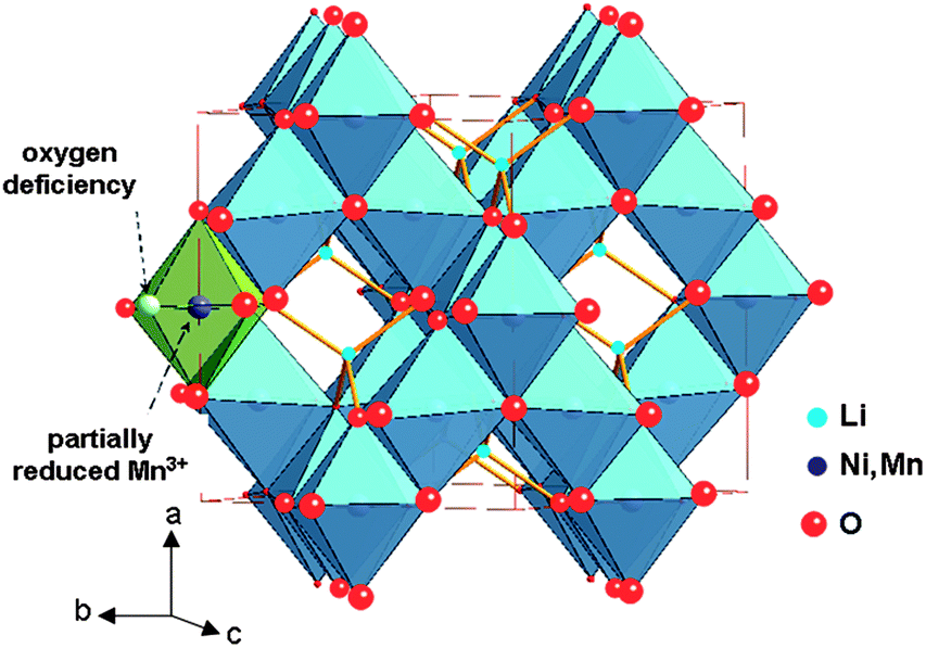 | ||
| Fig. 1 The structure of spinel LiNi0.5Mn1.5O4 (Fdm S.G.). Oxygen deficiency partially reduces Mn4+ to Mn3+ to satisfy local charge neutrality. | ||
The present review gives the state-of-the-art understanding of the properties of LNM and Cr-doped LNM materials. Owing to the evolution in this field, these compounds are promising active 5 V cathode elements for the next generation of Li-ion batteries to improve the technology of the energy storage and electric transportation. This progress is the fruit of about a decade of intensive research in the electrochemical community during which chemists, electrochemists, and physicists have added their efforts to understand the properties of the materials, although some obstacles still stay in the way before 5 V batteries can find their commercial use for worldwide applications in the industry.
B Synthesis
Previous studies have shown that the synthesis of single-phase LiNi0.5Mn1.5O4 is a difficult task; this is mainly due to the presence of undesired impurities such as NiO and LixNi1−xO in the final product, which deteriorates its electrochemical behaviour.21–24 Among the various methods used to prepare LNM powders as cathode materials for Li-ion batteries, the most popular are solid state reaction and wet chemical (solution synthetic) method with different morphologies and sizes.1 Ordered vs. disordered LNM
Ordering of the Ni2+ and the Mn4+ ions on the octahedral sites reduces the deviation from stoichiometry due to oxygen vacancies. The loss of oxygen can introduce a rock-salt impurity phase, i.e. Li2(NiMn)O3, and, as we shall see in Section 5, the appearance of a shoulder at ∼4.1 V vs. Li+/Li0 in the charge and discharge curves, which is indicative of the presence of Mn3+ in the spinel phase. The presence of the rock-salt impurity phase with a host spinel phase containing Mn3+ is commonly observed after firing at 800–1000 °C.25 Interestingly, cationic substitutions for Ni have been shown recently to prevent the formation of LixNi1−xO impurity and stabilize the spinel structure with a disordering of the Mn4+ and Ni2+ ions in the 16d octahedral sites. We shall return on this effect in Section 2.5. It also favors the cation disordered structure reflected in a transformation of the space group from P4332 to Fdm.22,26 During the synthesis of the LiNi0.5Mn1.5O4, however, the high calcination temperature sometimes leads to the reduction of the Mn oxidation state from +4 to +3. To cure this oxygen deficiency, some authors employed an annealing process at 700 °C in air after the high-temperature calcination at temperatures as high as 1000 °C, or 500 °C in oxygen atmosphere at high pressure.27,28 The resulting powders delivered flat voltage profiles at around 4.7 V. Idemoto et al.27 reported that LiNi0.5Mn1.5O4 synthesized under O2 atmosphere has the cubic spinel structure with a space group of P4332 instead of Fdm, as determined by neutron diffraction. Another approach to tune the ordered/disordered phase is an acute control of the cooling rate immediately after high temperature calcinations.29
2 Solid state reaction
Generally, the LiMn1.5Ni0.5O4 powders prepared by solid-state reaction (SSR) have a large deficiency in oxygen, which results in the appearance of a wide voltage plateau at 4.1 V vs. Li+/Li and the presence of a rock-salt impurity phase such as NiO or LixNi1−xO. It is thus detrimental to the electrochemical properties. The amount of impurity phase can be reduced by annealing the sample in high O2 pressure (at ca. 2 MPa).30 Spinel oxides were synthesized using carbonates,31 mixture of Li2Co3, NiO and electrolytic MnO2 as reactants.32–34 The study of non-stoichiometric Li1±xNi0.5Mn1.5O4 (x = 0.05, 0) powders synthesized by SSR revealed that the stoichiometric LNM has the best cycle performance.33 Modified solid-state reactions include a one-step process,35 mechanical activated SSR,36 and ball milling.37 To obtain pure LiNi0.5Mn1.5O4 powders, the molten salt method was employed with LiCl–LiOH mixed salts.203 Wet-chemical route
Many approaches have been used to synthesize LNM by wet-chemical methods or “chimie douce” using aqueous or alcoholic solutions providing high-purity spinel phase.38 These techniques include combustion method,39 co-precipitation method (CPM),40 ultrasonic CPM,41 two-dryness CPM,42 emulsion drying,43 oxalate co-precipitation process.44 The sol–gel method is the most popular technique to prepare spinel phases.45–47 Choy et al.46 prepared the spinel by a modified citrate route at a pH of 6.4 using Li carbonate and Mn nitrate. Lee et al.47 prepared the spinel from an aqueous solution of acetate salts. Pure LiNi0.5Mn1.5O4 phase was also produced using a chelating agent.48 Therefore, the material synthesized by the sol–gel method is expected to have enhanced electrochemical performance and has been extensively investigated. Cao and Manthiram proposed a novel synthetic approach using urea as a reservoir for CO2 to control the formation of LNM and optimize its morphology for high tap density.49 Various raw materials have also been used, including acetates, hydroxides, nitrates, mixture of precursors,50 or nitrate and polyvinyl acetate with subsequent decomposition at 150 °C.30 Idemoto et al.51 have investigated the crystal structure and the electrode performance as a function of sol–gel synthetic conditions. The obtained LNM electrodes fired at 700 °C showed a maximum discharge capacity of ca. 125 mA h g−1, and the capacity after 100 cycles was 95.1% of the initial one at low C-rate and at room temperature. Cabana et al.52 prepared by different synthetic routes, i.e. mixed hydroxide route and hydrothermal method, a series of LNM samples that displayed a variety of particle sizes and shapes, from nanometric to micrometric, with different anisotropies and assemblies. A modified Pechini method utilized metal nitrates dissolved in distilled water and added drop-wise to citric acid–ethylene glycol (1:4 molar ratio); this solution heated to 140 °C enables the chelation (reaction of functional carboxyl group of acid with metal ions) process for the esterification of acid with ethylene glycol. The final product is composed by primary crystallites of 50–70 nm size with a surface area of 15.6 m2 g−1.53
The co-precipitation synthetic route provides good crystallization of the Fdm phase with disordered Ni and Mn.54 This method is described as follows. Stoichiometric amounts of manganese, lithium, and nickel acetates (99% Aldrich) were first dissolved in distilled water and stirred for 1 h. Oxalic-acid solution was then added dropwise under stirring to obtain a green precipitate. The molar ratio of oxalic acid to metal ions was controlled to be 1:1. The precipitate solution was continually stirred for 1 h before being dried at 50 °C overnight with constant stirring. The dried precipitate was preheated at 500 °C for 6 h and then ground for 30 min. The preheated powder was pressed into pellets (20 mm dia. and ca. 5 mm thick) and annealed at 900 °C for 24 h in air for better crystal growth. Fig. 2 shows typical SEM and TEM images used to characterize the crystallite size and surface morphology of LNM spinel particles. The samples are not only well crystallized, but the powder particles consist of many small grains, most of the observed grains are >0.2 μm without serious agglomeration after annealing at 900 °C for 24 h in air (Fig. 2a). The grains are well crystallized with sharp corners. Some of the grains are thick disks. However, the TEM images (Fig. 2b and c) indicate a polycrystalline microstructure within the particles with nano-size domains of different orientations, some disordered areas, and bent lattice fringes.
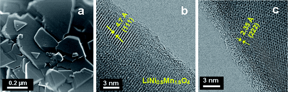 | ||
| Fig. 2 SEM and TEM images of the LNM particles synthesized by co-precipitation. | ||
4 Other methods
Other synthesis routes are also commonly used including spray pyrolysis,55 and derivatives methods such as spray drying,56 ultrasonic spray,57 ultrasonic spray pyrolysis,58 spray pyrolysis associated with internal combustion-type.59 However, the size of the particles obtained by this technique is the order of a micrometer, while smaller particles can be obtained by other techniques including the wet chemistry reviewed in the previous section. The use of polymers containing oxygen-based functional groups [polyethylene glycol (PEG), poly(methyl methacrylate) (PMMA)] has been studied to synthesize highly crystalline nanometric LNM spinel.11 In the presence of oxalic acid and polymer followed by heating at 800 °C for a few minutes is sufficient to obtain pseudo-polyhedral particles ranging from 60–80 nm in size.5 Impurity removal
The synthesis of disordered LNM is often accompanied by oxygen loss at high temperature (>715 °C), which results in non-stoichiometric LiNi0.5Mn1.5O4−™.20 We have already mentioned that the oxygen removal in LNM may introduce Li2(NiMn)O3 and LixNi1−xO impurities, while partially reducing Mn4+ to Mn3+ to satisfy local charge neutrality. To suppress the LixNi1−xO impurity phase and improve the electrochemical performance, various cation substitutions have been pursued.60–63 It was found that equal amounts of Cr3+ substitution for Ni2+ and Mn4+ improves the rate capability especially for LiNi0.45Mn1.45Cr0.1O4, due to the segregation of Ni from the surface to the bulk as indicated by energy-dispersive X-ray (EDX) analyses.62 However, there are still some Ni-based impurities and, as we shall see in Section 5, a small 4.1 V Mn3+/Mn4+ redox plateau for the whole series of Cr-substituted LNM. Recently, we used a post-annealing strategy at lower temperature to modify the oxygen deficiency and suppress the Mn3+ content while maintaining the disordered structure.64 With the post-annealing strategy, a pure LiNi0.45Mn1.45Cr0.1O4 disordered phase was successfully synthesized. In the following, we report a comparative analysis of the properties of this Cr-doped LNM, i.e. LiNi0.45Mn1.45Cr0.1O4, and a pristine LNM (commercial sample from Energy Innovation Group (EIG), Korea).C Structural properties
1 X-ray diffraction
Fig. 3a presents the XRD patterns of the spinel samples fired at different temperatures. The peaks at ca. 2θ = 37.7 and 43.6° are due to the rock-salt impurity phase; their intensity increases with increasing sintering temperature Ts from 700 to 900 °C as a result of the oxygen loss at high temperature. This growth of the impurity phase is correlated with an increase of the lattice parameter by 0.15% between Ts = 700 and 900 °C, proof that some oxygen is removed from the host at such temperatures. It is not possible to identify the nature of the impurity, although it is presumably associated with Li2MnO3, because its composition varies with Ts, as can be seen in Fig. 3a from the shift of the impurity peak with Ts. Interestingly, the impurity diffraction lines are absent in Cr-doped sample after it was re-annealed at 600 °C, indicating that post annealing is an effective way to eliminate the impurity phase. Moreover, the lattice parameter is increased by 0.34% in the annealing process, so that oxygen is reinserted. On the other hand, it has been reported that the spinel LNM undergoes a thermally induced order/disorder transition at ∼700 °C.65 Therefore, we assume that re-annealing at 600 °C only helps modify the oxygen deficiency while maintaining the disordered structure. In order to characterize the order/disorder of the LNM sample, Rietveld refinement of XRD data was carried out with the Fullprof program in the space group with Li in 8a sites and transition metals statistically distributed in 16d sites. The well-fitted refinement profile given in Fig. 3b for the final sample confirms that the LNM spinel still retains the disordered structure (S.G.). Moreover, Rietveld refinement also gives the cubic lattice parameter a = 8.16559 Å, which is close to the value for ordered LNM,20,66 but different from a previous result of 8.17846 Å.62 Since the ionic radius of Mn4+ is smaller than that of Mn3+ and since the increased lattice parameter with the presence of Mn3+ results from the oxygen deficiency at high temperature, it is reasonable to conclude that there are fewer Mn3+ ions after re-annealing at 600 °C. From the Scherrer's formula:| L = 0.9λ/Bcosθ, | (1) |
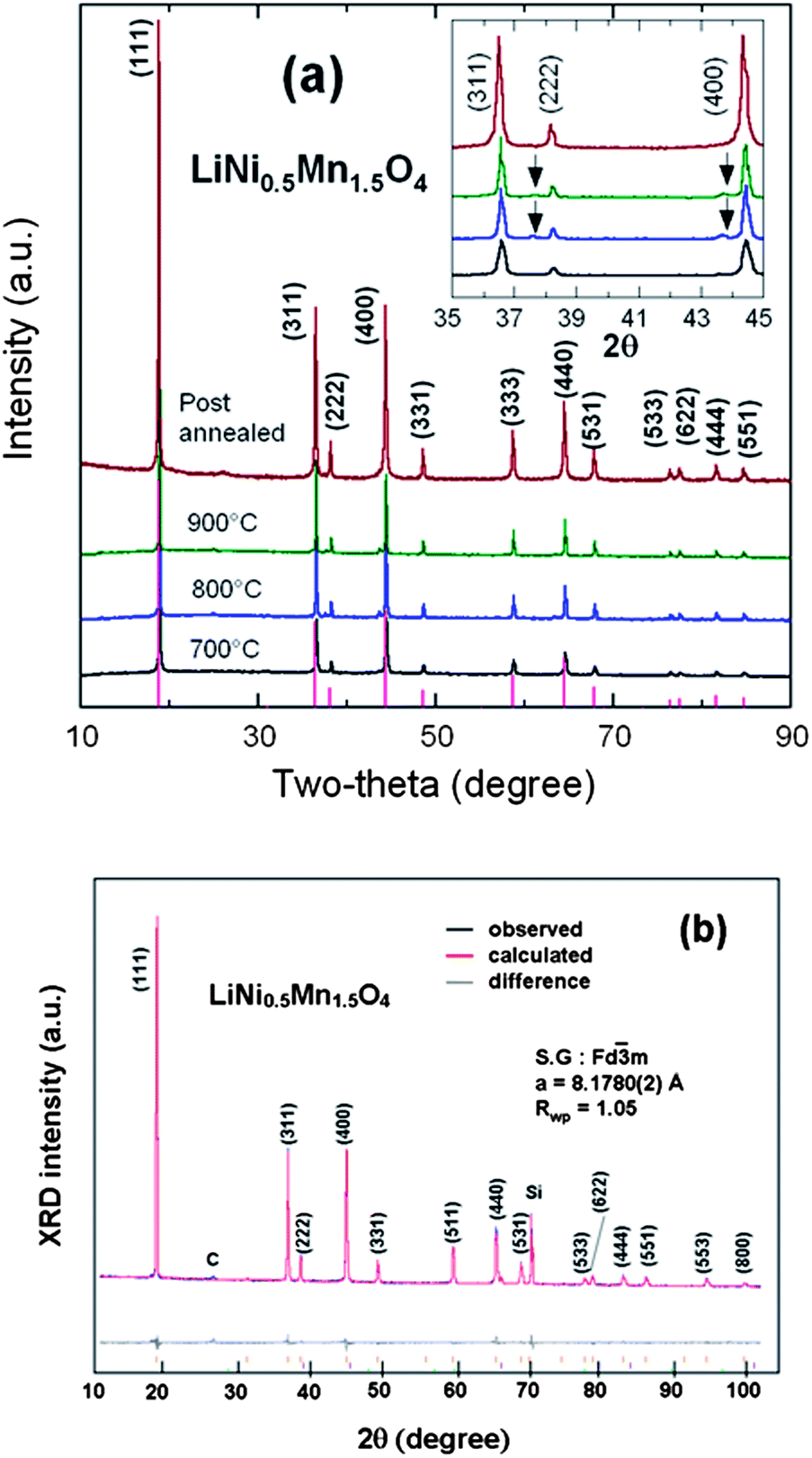 | ||
| Fig. 3 (a) XRD patterns of the spinel samples at different steps of the synthesis in the temperatures range 700–900 °C before annealing, and for the final sample, post-annealed at 600 °C for 48 h. Inset shows the magnified Bragg lines between 2θ = 35–45° with impurity peaks marked by arrows (b) Rietveld refinement profiles of the XRD data for the LNM electrode film (Si peak comes from sample holder). Reproduced with permission.64 | ||
Note that similar results were obtained for LiNi0.45Mn1.45Cr0.1O4. The same post-annealing strategy at 600 °C as in the case of pristine LNM was used to modify the oxygen deficiency during synthesis of the LiNi0.45Mn1.45Cr0.1O4 cathode for lithium-ion batteries. Structural analyses revealed that post-annealing is an effective way to eliminate the impurity phase without changing the space group. In addition, we found that substitution of Cr3+ for Ni2+ and Mn4+ not only helps to keep the Mn4+ oxidation state unchanged (2Cr3+ = Ni2+ + Mn4+), but also introduces greater disorder of the B-site cations in LNM,62 as we shall see in Section 3.2. This feature will explain why the small amount of Cr substituted for Ni and Mn leads to better rate performance along with cyclability at room temperature, as we shall see in Section 5. The variation with thermal treatment of the particle size and morphology were examined by SEM.64 Images of the disordered LiNi0.45Mn1.45Cr0.1O4 (Fig. 4) represent the well-crystallized material with a particle size in the range of 0.5–2 μm. The micrographs reveal that the post-annealing at 600 °C promotes well-faced grains of regular shape characteristic of the cubic spinel morphology.
 | ||
| Fig. 4 SEM and TEM images of Cr-doped LNM sample post-annealing at 600 °C. | ||
2 Vibrational spectroscopy
FTIR and Raman scattering spectroscopy are powerful techniques to distinguish the order from disorder in LNM,38,53,65 also used in this work to further investigate the order/disorder change of our samples according to the synthesis parameters. The FTIR spectra of the LiNi0.45Mn1.45Cr0.1O4 sample obtained at different steps of the synthesis are compared in Fig. 5a. The Ni–O stretching vibration at 588 cm−1 and the stretching vibration of Mn–O at 619 cm−1 dominate the spectra. The characteristic bands (at around 430, 468, 558, and 650 cm−1) corresponding to the cation-ordered structure have a large intensity only in the spectra of the sample fired at 700 °C and are almost absent in the spectra of the other samples, which confirms that the order/disorder transition only occurs at ∼700 °C.20,38,65,67 A semi-quantitative measure of the degree of cation ordering in the spinel sample can be additionally characterized by ratio of the intensity of the main band at 619 cm−1 over that of the main additional band present only in the ordered (P4332) phase at 550 cm−1: the larger this ratio, the larger the cation disorder at the molecular range probed by the FTIR technique. Then, the comparison between the FTIR spectrum of the Cr-doped LMN sample and that of the pristine sample post-annealed at 600 °C in Fig. 5a shows that the pristine LNM sample is in a more ordered phase than the Cr-doped sample. Despite the fact that the cations are disordered in the S.G. or Oh7 spectroscopic symmetry, we find that the FTIR spectrum has well-resolved stretching modes in contrast to the typical spinel LiMn2O4 exhibiting overlapping broad bands.38 These vibrational-spectroscopy results can be understood in terms of short-range Ni2+, Mn4+ cation ordering on the octahedral sites.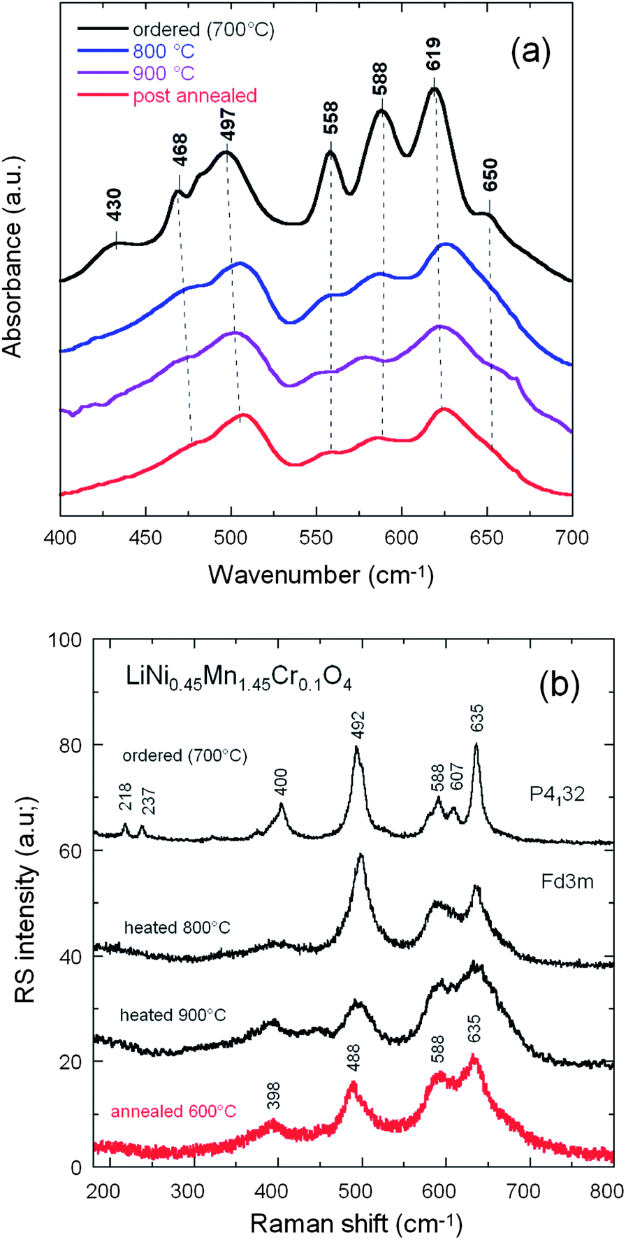 | ||
| Fig. 5 FTIR (a) and Raman scattering (b) spectra of the LiNi0.45Mn1.45Cr0.1O4 samples obtained at different steps of the synthesis: at different temperatures up to 900 °C before annealing, and for the final sample, post-annealed at 600 °C for 48 h. | ||
The degree of Ni/Mn ordering in the surface layers of the three samples was also investigated with Raman scattering spectroscopy.38,54,68Fig. 5b shows a typical Raman spectrum of crystallized Li[Ni0.5Mn1.5]O4 sample. The octahedral Mn(Ni)O6 structural units have Oh symmetry where the 625 cm−1 peak assigned to the symmetric Mn–O stretching vibration of the MnO6 octahedra in Li[Mn2]O4 is shifted to 635 cm−1. The new features at 399 ± 1 and 490 ± 2 cm−1 are strong and can, therefore, be assigned unequivocally to the Ni–O stretching mode. Two effects contribute to the frequency shift of the Mn–O stretching mode: (a) the increased mean valence state of the Mn ions and (2) a smaller unit-cell volume. None of the peaks characteristic [18] of ordering of the Ni(II) and Mn(IV) in space group P4332 (or P4132), viz. at 218, 237 and 607 cm−1, were detected, which is another indication that the Ni(II) and Mn(IV) of LNM samples were disordered over the 16d sites of the spinel.
Although the vibrational spectroscopy proved very useful to evaluate the degree of cation disorder, it failed to give details on the concentration of oxygen vacancies. In particular, the Mn3+–O stretching mode well observed at circa 518 cm−1 in LiMn2O4 is not detected in our samples. The determination of the concentration of Mn3+ ions then requires another means of investigation. We show in the next section that the investigation of magnetic properties fulfils this purpose.
3 Magnetic properties
From now on, we only consider the pristine and Cr-doped samples pot-annealed at 600 °C. Fig. 6a shows the temperature dependence of the reciprocal molar magnetization normalized by magnetic fields (H/M) under an applied field H = 10 kOe for the un-doped and Cr-doped LiNi0.5Mn1.5O4 spinel grown by wet-chemical route. The two samples undergo a magnetic transition at a temperature TC = 129 K in LMN, shifted to 117 K in Li[Ni0.45Mn1.45Cr0.1]O4. We argue hereunder that this lowering of TC is the signature of a reduced amount of short-range order of the Ni2+ and Mn4+ ions. Fig. 6b displays the field dependence of the magnetization for the Cr-doped spinel at different fixed temperatures. Below 150 K, nonlinearity is clearly observed, suggesting the presence of a strong ferromagnetic contribution. At low temperatures, a typical magnetization curve shows a rapid increase with magnetic field; the magnetic saturation is obtained at a relatively small field. Several authors have reported such a magnetic behavior. Blasse has shown the ferromagnetic spin alignment below 130 K in LiNi0.5Mn1.5O4.17 Strobel et al.69 found a large increase in the magnetic susceptibility at low temperature, starting at ca. 120 K on cooling. These features were attributed to the formation of clusters resulting from a strong magnetic frustration in the structure. Results by Nakamura et al.70 have shown that the asymptotic Curie temperature moved in the positive direction and changed its sign from negative to positive around y = 0.2 in LiNiyMn2−yO4 spinels.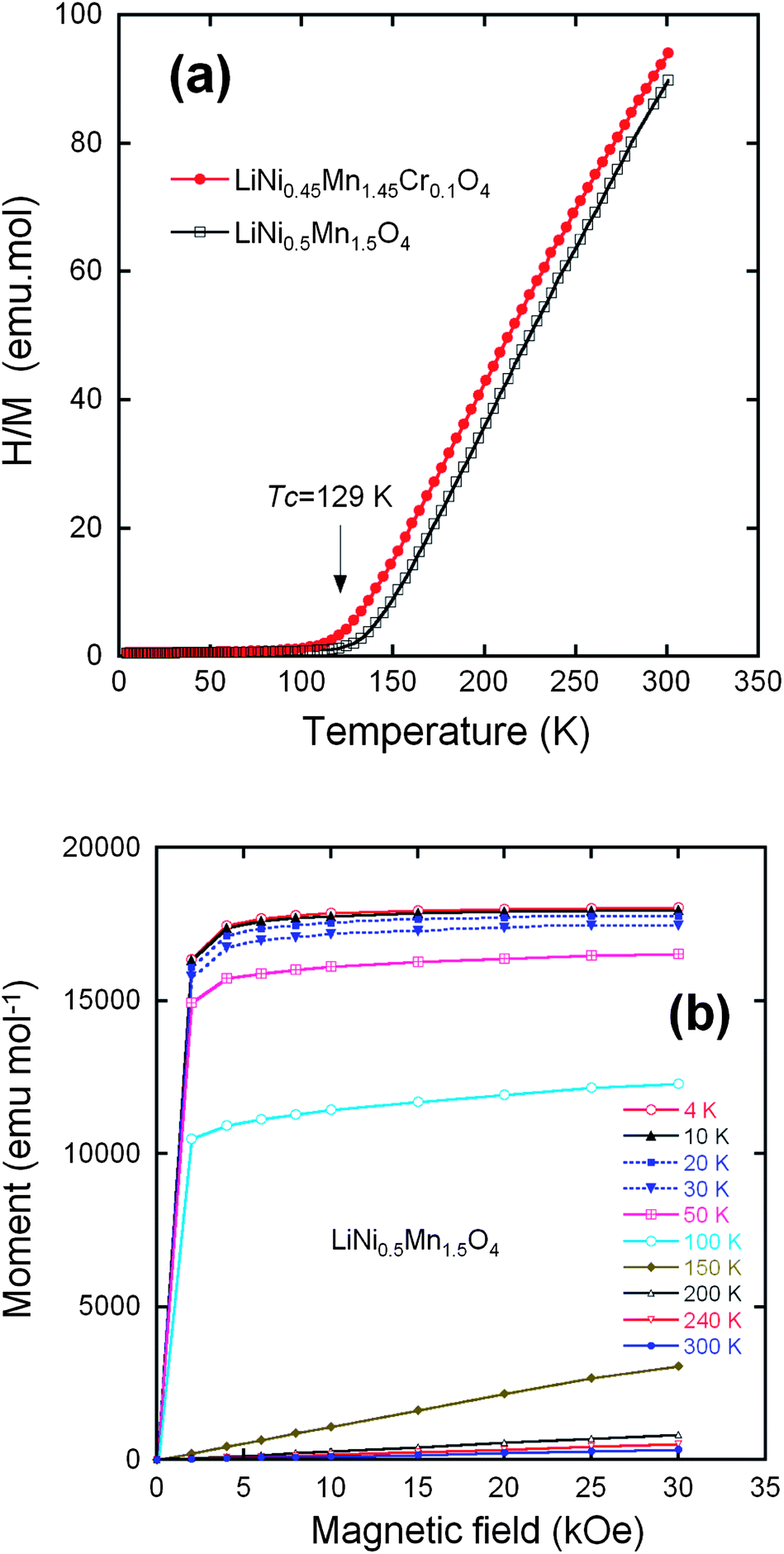 | ||
| Fig. 6 (a) Inverse of the magnetic susceptibility H/M measured at H = 10 kOe, for the LiNi0.45Mn1.45Cr0.1O4 samples after post annealing at 600 °C and the LiNi0.45Mn1.45Cr0.1O4 crystallized in the same Fdm space group. (b) Magnetization curves of the LiNi0.5Mn1.5O4 sample crystallized in the Fdm space group. Reproduced with permission.64 | ||
Electron transfer from the half-filled Ni2+ σ-bonding eg orbital to a half-filled Mn4+ π-bonding tg orbital in a 90° Ni2+–O–Mn4+ interaction via a common pσπ orbital is restricted by the Pauli exclusion principle to give an antiferromagnetic Ni2+–Mn4+ interaction.71 Ordering of the Ni2+ and Mn4+ ions in the P4332 Li[Ni0.5Mn1.5]O4 long-range-ordered phase has been shown to give a ferrimagnetic phase at TC with antiferromagnetic coupling between the Ni2+ and Mn4+ sublattices.19 Frustrated magnetic interactions in a completely disordered phase would give a much lower magnetic ordering temperature than in the ordered phase. Therefore, the existence of long-range magnetic order below a TC similar to that of the ordered P4332 phase is a signature of a strong correlation function Cij = 〈P(Mn)iP(Ni)j〉 with P(Mn)iP(Ni)j the probability that if site i is occupied by Mn, site j is occupied by Ni and Cij is large if i and j are nearest 16d-sites. The fact that the peaks of the XRD spectra reported above are well-described in the framework of the disordered phase means that the correlation length Cij is smaller than the length scale probed by XRD, typically a few nm (only an analysis of the diffusive X-ray scattering would give access to the correlation function at shorter length scale). The FTIR in the previous section, which is a probe at the molecular scale, already gave evidence of short-range ordering at this scale. The short-range order is confirmed by the magnetic experiments, which are a probe at the atomic scale and show that the crystal has a large degree of order at the scale of the nearest neighbours.
For long-range order, the saturation magnetization at low temperature results from the difference between the magnetic moment carried by Mn4+ and Ni2+. The orbital moment at Mn4+ and Ni2+ is quenched by the crystal field, which makes a spin-only atomic magnetic moment a good approximation. The spins of Mn4+ and Ni2+ are S = 3/2 and S = 1, respectively, so the magnetic moment at saturation for the ordered LiNi0.5Mn1.5O4 should be (3 × 1.5 − 2 × 0.5) = 3.50 μB per formula unit. The experimental value of the saturation magnetization 3.40 μB/formula unit at 4.2 K of the phase (Fig. 6b) is in reasonable agreement with the theoretical value for a fully ordered phase and shows the absence of Ni3+ ions that would have raised the magnetic momentum to a larger value, as it has been observed in some cases in LNM, ordered or not. The saturation magnetization in the LiNi0.45Mn1.45Cr0.1O4 sample is only reduced to 3.2 μB per formula unit. This result suggests that the Cr3+ are not distributed randomly, but tend to form antiferromagnetically coupled dimers randomly distributed in the lattice. This is actually expected and implicit in the notation 2Cr3+ = Ni2+ + Mn4+. Two Cr3+ on nearest 16d sites form the most favourable configuration to lower the energy for two reasons: first, 2Cr3+ insures charge neutrality at the molecular scale when substituting for Ni2+ + Mn4+, thus minimizing the cost in Coulomb energy; second, the ionic radii r satisfy approximately the relation 2r(Cr3+) ≈ r(Mn4+) + r(Ni2+), so that this substitution also minimizes the lattice distortion. The concentration of Cr is only 5% of the metal ions, i.e. far smaller than the percolation threshold of the 16d-site sublattice, and thus too small to destroy the long-range ferrimagnetic ordering at finite temperature; it is, however, responsible for a decrease in the short-range Mn4+, Ni2+ order and, therefore of the Néel temperature by 12 K that is observed with respect to LiMn1.5Ni0.5O4. In addition, if we subtract the magnetic moment carried by the Cr3+, 0.3 μB per formula, from the Mn and Ni contribution to the magnetic moment at saturation in the antiferromagnetic phase of LiNi0.45Mn1.45Cr0.1O4, we find 1.45 × 3 − 0.45 × 2 − 0.3 = 3.15 μB in agreement with the experimental value 3.2 μB.
D Electronic properties
1 Density of states and fermi energies
The open-circuit energy diagram of a lithium battery has been discussed by Goodenough et al.1 If the active transition-metal cation contains a localized d-electron manifold, the manifold acts as a redox couple, e.g. Ni2+/4+ in LiNi0.5Mn1.5O4 spinel. Successive redox couples are separated by an on-site energy U, and the effective U is larger when augmented by either a crystal-field splitting or an intra-atomic exchange splitting.1 However, when the Fermi energy EFC of the cathode approaches the top of the anion p bands of the host, p–d covalent mixing may transform the d electrons at the EFC into band electrons occupying one-electron states. In the absence of a crystal-field splitting of the d orbitals at EFC, as occurs for Ni(IV) to Ni(II), the one-electron states are not separated by an on-site energy U and there is no step in the voltage of the battery as EFC is moved from one formal valence state to another one upon the reduction or oxidation of the host. The voltage vs. lithium that can be obtained with a solid cathode host is constrained by either the intrinsic limit of the cathode host or by the decomposition voltage of the electrolyte if not by the voltage of the electrolyte's highest occupied molecular orbital (HOMO). The intrinsic limit of a host transition-metal compound is the voltage at which EFC becomes “pinned” at the top of the anion p bands.1Fig. 7 reports the schematic density of states and Fermi energies for the LixNi0.5−yMn1.5−yCr2yO4 spinel cathode. In this case, it may be possible to access two formal valences on the active cation without a voltage step on passing from one formal valence state to the next. However, when EFC of the host falls below the HOMO of the electrolyte, a passivating, Li permeable SEI layer must form on the surface of the active particle if a reversible reaction is to be obtained. If the passivating SEI layer is not permeable to Li+ ions, it blocks insertion/extraction into/from the host. The HOMO of a liquid carbonate electrolyte is about 4.3 eV below the Fermi energy EFA of a lithium anode, and the decomposition voltage of the electrolyte is at about 5 eV below it. Access to Ni(III) and Ni(IV) valence states is possible in cation disordered LiNi0.5Mn1.5O4 spinel; the SEI layer formed at voltage V >4.3 V is self-limiting and Li-permeable.
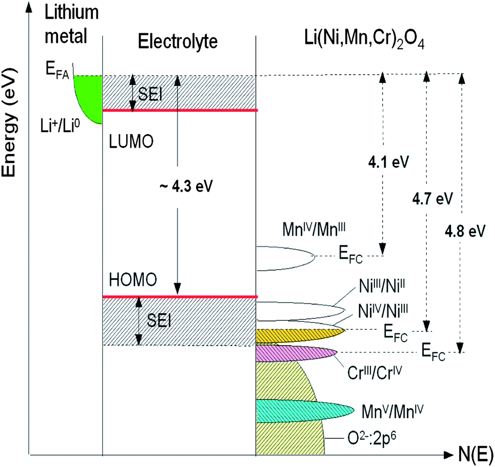 | ||
| Fig. 7 Schematic density of states and Fermi energies for LixNi0.5−yMn1.5−yCr2yO4 spinel cathode. The Li permeable SEI layer formed on the electrode surface preserves the overall reversible reaction. | ||
2 Typical voltage profile
Fig. 8 shows the typical voltage profile upon charging a Li//Cr-doped LNM cell recorded at a low rate of C/5. According to the previous considerations, one observes the various redox reactions Mn3+/4+ (at 4.1 V), Ni2+/4+ (at 4.7 V) and Cr3+/4+ (at 4.8 V). The characteristic 4.1 V plateau is always observed in the pristine or metal-doped LNM cathodes as a result of oxygen loss at high-temperature synthesis.61–63 However, no obvious 4.1 V step was detected in Cr-doped spinel post-annealed at 600 °C, confirming that most of the residual Mn3+ ions have been re-oxidized to Mn4+ after heat treatment in agreement with the analysis of magnetic properties. The narrower voltage separation, ΔV, between the two plateaus corresponding to the oxidation peaks of Ni2+/4+ in the LNM spinel is indicative the degree of cation ordering on the octahedral 16d sites. The value ΔV = ∼40 mV for the pristine LNM compared to those ΔV = ∼70 mV of the Cr-doped LNM is reminiscent of the higher degree of cation ordering in this cathode. | ||
| Fig. 8 Typical voltage profile of charge of a Li//Cr-doped LNM cell showing the various redox reactions Mn3+/4+ (at 4.1 V), Ni2+/4+ (at 4.7 V) and Cr3+/4+ (at 4.8 V). | ||
3 Spin configuration
The electrochemical reaction in LixNiyMn2−yO4 has been described by studying the top of the valence band of LiNiyMn2−yO4 for a series of samples with 0.0 < y < 0.5.7 A partial density of states attributed to Ni 3d electrons is located about 0.5 eV above that of the Mn 3d eg electrons. When y = 0, the voltage plateau of Li//LiMn2O4 is located at 4.1 V. As y increases, the capacity associated to the 4.1 V plateau decreases as 1 − 2y Li per formula unit and a new plateau at 4.7 V appears. The capacity associated to the 4.7 V plateau increases as 2y Li per formula unit, so that the total capacity of the samples (the sum of the contributions from the 4.1 and 4.7 V plateaus) is constant. This is taken as evidence that the oxidation state of Ni in these samples is +2, and therefore they can be written as Li+Niy2+Mn1−2y3+Mn1+y4+O42−. The 4.1 V plateau is related to the oxidation of Mn3+ to Mn4+ and the 4.7 V plateau to the oxidation of Ni2+ to Ni4+. The reason for this behaviour could be given by considering the positions of the energy levels shown in Fig. 9. The crystal field splits the 3d levels of Mn and Ni octahedrally coordinated with oxygen into eg and t2g levels.7 For Mn3+, among the four 3d4 electrons with majority spin (↑) three electrons are on t2g(↑) and one electron is on eg(↑). The 3d8 electrons of Ni2+ have six electrons on the t2g(↑↓) levels and two electrons on the eg(↑) level. When an electron is removed from Mn3+, it is removed from the Mn eg(↑) state that has an electron binding energy at around 1.5–1.6 eV, and this is on the 4.1 V plateau. When there are no more electrons left on Mn eg(↑) (all Mn are oxidized to Mn4+), then electrons are removed from Ni eg(↑) that has an electron binding energy of about 2.1 eV, and the voltage plateau moves up to 4.7 V because of the increased energy needed to remove electrons.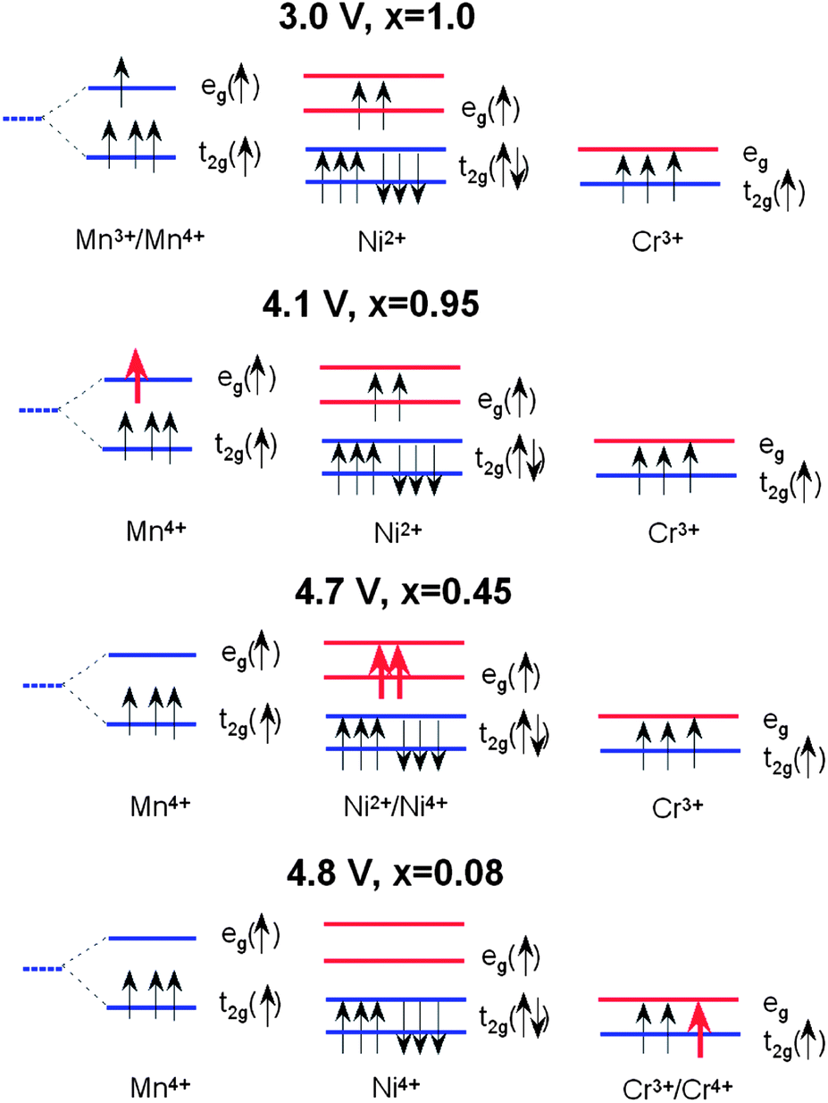 | ||
| Fig. 9 Schematic diagram showing the 3d electronic levels of Mn3+, Ni2+ and Cr3+ in LiNi0.5−yMn1.5−yCr2yO4 spinel during the charge process. It is noted that Ni2+ favours the low-spin configuration in LiNi0.5−yMn1.5−yCr2yO4. Partially empty levels are shown with red arrows. | ||
In the case of Cr-doped spinel, the last step of the charge, after all the Mn have been oxidized to Mn4+ and Ni to Ni4+, proceeds with the oxidation of Cr3+ ions at an upper voltage plateau according to the reaction:
 | (2) |
Fig. 9 shows the change in the occupation of the energy levels in LixNi0.5−yMn1.5−yCr2yO4 spinel during the charge process (x ≈ 0.08) according to this model. Considering the electronic states, the energy difference ΔE = 0.5 eV between the Mn eg level and the Cr t2g level corresponds to the potential difference between the two plateaus of the discharge profile for the Li//LiMn2−yCryO4 cell (see Fig. 10).
 | ||
| Fig. 10 Charge–discharge curves of the un-doped and Cr-doped LNM cathodes in CR2032 coin cell composed of LiPF6 in EC–DEC (1:1) as electrolyte. The cathode electrode contained 89 wt% active material, 6 wt% conductive carbon, and 5 wt% PVdF binder (loading 5 mg cm−2). All cells were cycled at 25 °C between 3.5 and 4.9 V at C/5 rate. | ||
E Electrochemical performance
The electrochemical properties of the un-doped and Cr-doped spinel cathodes were investigated in CR2032 coin cells composed of LiPF6 in 1:1 ethylene carbonate–diethylene carbonate (EC–DEC) as electrolyte. Fig. 10 shows the initial charge–discharge cycle at a low rate of C/5 for both cathode materials. The characteristic 4.1 V Mn3+/Mn4+ redox couple is always observed in the pristine or metal-doped LNM cathodes before post-annealing as a result of oxygen loss at high-temperature synthesis.61–63
However, in Fig. 10 obtained for the samples post-annealed at 600 °C, no obvious 4.1 V step is detected in LiNi0.45Mn1.45Cr0.1O4 spinel (red curves), confirming that most of the residual Mn3+ ions have been re-oxidized to Mn4+ after re-annealing at 600 °C in agreement with the analysis of magnetic properties. This is also consistent with the Rietveld refinement of the XRD spectra. However, a small anomaly near 4.1 V can be detected on the discharge curves, pronounced in the case of the un-doped LNM, which suggests that Cr-doping can reduce, but not avoid entirely a loss of oxygen with time during cycling. We shall return to this problem in Section 7. In addition, LiNi0.45Mn1.45Cr0.1O4 shows two distinct plateaus at around 4.7 V. In contrast, the un-doped sample only exhibits a single flat voltage profile at about 4.7 V. No obvious great change was found after 100 cycles, suggesting good reversibility for both samples.
In order to understand the difference in the electrochemical properties of the LiNi0.5Mn1.5O4 and LiNi0.45Mn1.45Cr0.1O4 spinel cathodes, Fig. 11 compares the incremental capacity dQ/dV vs. V graphs, where Q = ∫Idt from t = 0 at 3.5 V to t at V–3.5 calculated from curves in Fig. 10. Removal of Li from the tetrahedral sites of the spinel LNM framework initially probes the oxidation reaction of Ni2+ → Ni3+ just below 4.7 V (typically ∼4.69 V) for the disordered Fdm and above 4.7 V (typically ∼4.72 V) for the ordered P4332 spinels.68 Ordering of the Ni and Mn raises by ∼0.02 eV the V(x) profile of LNM. From Fig. 11a, two anodic peaks at 4.663 and 4.731 V plus two cathodic peaks at 4.638 and 4.704 V were observed for the LiNi0.45Mn1.45Cr0.1O4, which is in agreement with two voltage plateaus for disordered LNM.20,68 Kim et al. suggested that, as the crystallographic structure changed from Fdm to P4332, the voltage gaps between the two plateaus became narrower at around 4.75 V and resulted in a flatter voltage profile.67 This separation is known to decrease from about 60 mV to around 20 mV, depending on the degree of ordering.66–68 The average potential difference, ΔV, between these two peaks is ca. 60 mV for the Cr-doped LNM material and 30 mV for the commercial sample. Therefore these results corroborate the much stronger cation disorder induced by the Cr-doping. Additionally, small redox peaks were observed in the LiMn1.45Cr0.1Ni0.45O4 at about 4.85 V, showing the redox reaction between Cr3+ and Cr4+ and confirming the electrochemical activity of Cr in the Cr-substituted LNM.
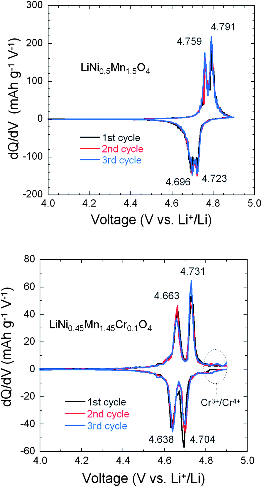 | ||
| Fig. 11 Differential capacity curves, dQ/dV vs. V, of the un-doped LNM (top) and LiNi0.45Mn1.45Cr0.1O4 (bottom). The values at the peaks are given in volt. Reproduced with permission.64 | ||
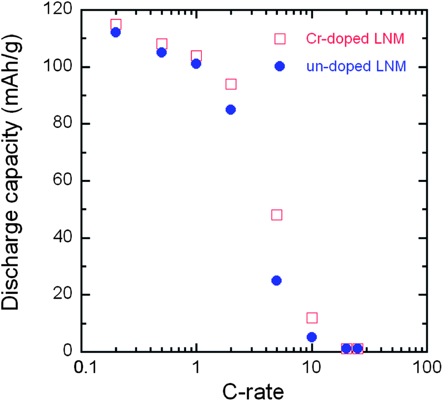
The smaller ΔV in un-doped LNM compared to that of LiNi0.45Mn1.45Cr0.1O4 suggests faster lithium insertion/extraction kinetics in the former.72 This is, however, controversial because it is well known that the cation disorder and the decrease of the concentration of defects such as oxygen vacancies is beneficial to the electrochemical performance. Therefore, the LiNi0.45Mn1.45Cr0.1O4 should have the best properties, and actually, this was the motivation for Cr-doping. Some insight into the insertion/extraction of Li is provided by the modified Peukert plot in Fig. 12 for both un-doped and Cr-doped LNM cathodes. The capacity loss after 25 cycles at 5 C rate is 32.4% and 16.3%, respectively. It is necessary to note that only 6% of conductive carbon was used to make the cathode electrode in this work.
 | ||
| Fig. 12 Modified Peukert curves of LNM and LiNi0.45Mn1.45Cr0.1O4 spinel cathodes cycled between 3.5 and 4.9 V in CR2032 coin cell with LiPF6 in EC–DEC (1:1) as electrolyte. | ||
From Fig. 12, the LiNi0.45Mn1.45Cr0.1O4 exhibits better rate capability and capacity retention than LiNi0.5Mn1.5O4. For instance, the LiNi0.45Mn1.45Cr0.1O4 delivered a reversible capacity of ∼115, 104, 95 and 40 mA h g−1 at C/5, 1 C, 2 C and 5 C, respectively; the un-doped LNM offered a lower reversible capacity of ∼110, 98, 85 and 12 mA h g−1 at the same C rates. When returned to C/5 from 5 C after 100 cycles, about 99% of reversible capacity was retained for LiMn1.45Cr0.1Ni0.45O4vs. 94% for un-doped LNM. These results give evidence that the electrochemical properties of the Cr-doped sample are definitely better than those of the un-doped sample at high C-rate, as expected. Therefore, the lower value of ΔV in un-doped LNM cannot be attributed to lower kinetics in the Cr-doped sample. To understand this difference in ΔV between the two samples, the phase diagram must be investigated; this is the purpose of the next section.
F Phase diagram
The phase evolution during lithium de-intercalation/intercalation within these two spinels has been studied using both ex situ,67,73 and in situ X-ray diffraction techniques.53,74–77 Conflicting results have been reported. In the ordered LNM, three distinct cubic phases were detected relating to each of the Ni2+, Ni3+, and Ni4+ oxidation states in the ordered LNM material. These phases transformed from one to another by means of two distinct two-phase regions that correspond to the wide voltage plateaus observed in the electrochemical profile of the cathodes.20,53 In contrast, the disordered LNM material showed a smooth peak shift to higher angles with no clear two-phase region until nearing the end of charging, which is observed by less pronounced plateaus in the voltage profiles.20,53 On the other hand, a structural change has been reported upon delithiation of disordered LixNi0.5Mn1.5O4 at x = 0.5 with loss of the glide symmetry.67 However, a different phase diagram has been reported for this same disordered LNM, with a solid solution for large values of x, followed with a two-phase region at x ∼0.6, with the onset of a second cubic phase, phase II, and another two-phase region at x <0.4, where phase II coexists with another cubic phase, phase III.74 Rhodes et al.75 found the three phases co-existing in a finite range of concentrations. However, the authors did not specify if their measurements were made on ordered or disordered LNM. We can simply note that their result is in agreement with the phase diagram found for LNM in the ordered phase, since the three phases are found to co-exist only in this case.74 Moreover, the phase diagram is reported to depend on the morphology of the particles.76Since the disordered LNM outperforms the ordered LNM as a cathode element for Li-ion batteries, we found it desirable to clarify the phase diagram of LNM in the disordered phase. The purpose of this work is to report the study of the structural changes of LNM during lithium extraction and insertion by in situ XRD measurements. Since, in addition, oxygen vacancies have undesirable effects mentioned above; this investigation has been made both on un-doped and Cr-doped LNM that is free of oxygen vacancy.64,77 The differences in phase evolution were compared and the effect of Cr substitution is discussed.77
The evolution of in situ XRD patterns of the Cr-doped LNM electrode during the cycling at C/24 rate is reported in Fig. 13, in which (311) and (511) Bragg lines have been selected to understand better the phase evolution. Overall, all the diffraction peaks shifted to the higher 2θ angles as the Li+ ions were removed from the two host structure. The analysis of the XRD pattern shows that all the phases are cubic, and the lattice parameters for each phase as a function of x over one charge–discharge cycle are reported in Fig. 14.
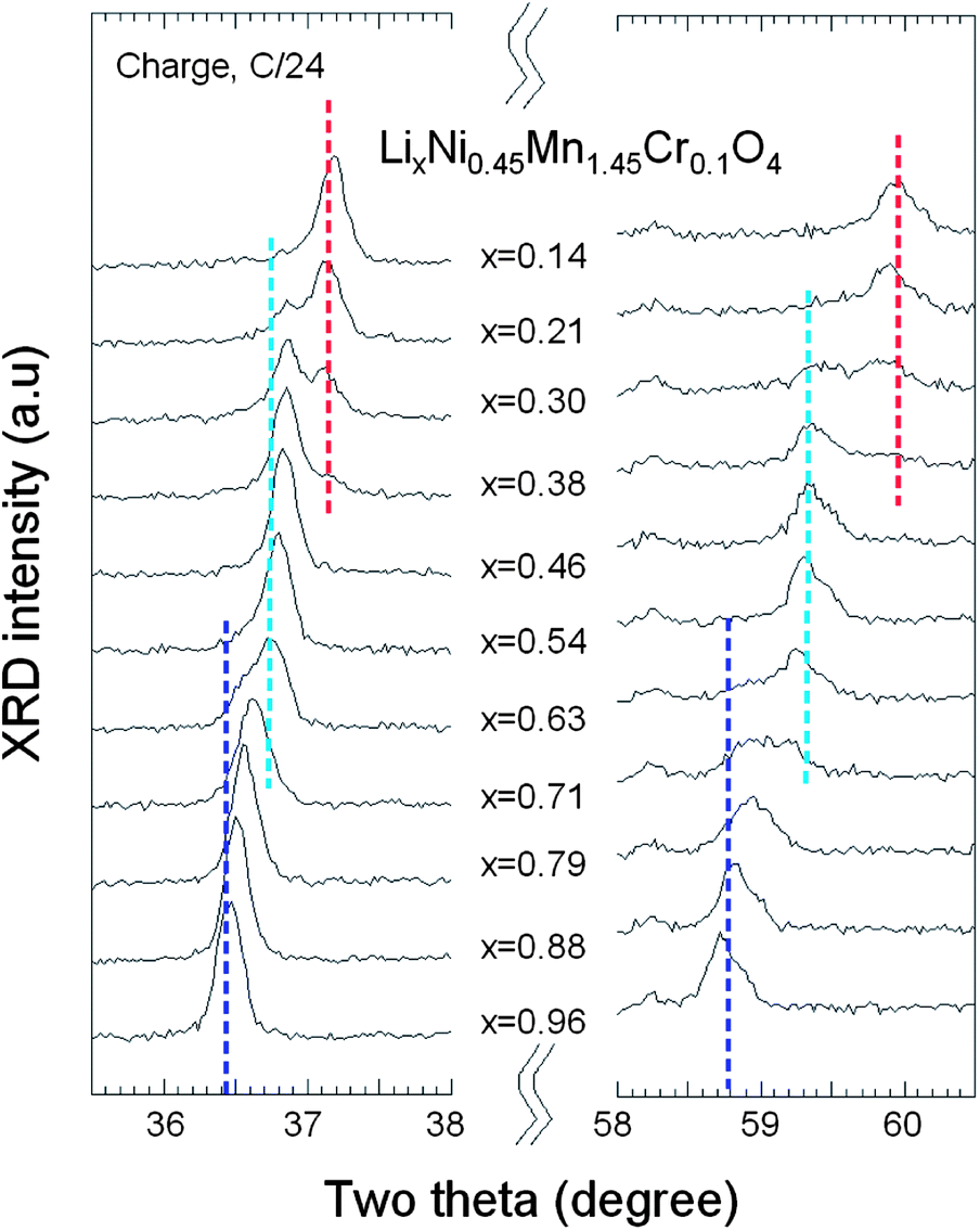 | ||
| Fig. 13 In situ XRD patterns of the (311) and (511) peaks as a function of x(Li) of Cr-doped LNM spinel during the charge at C/24 rate. | ||
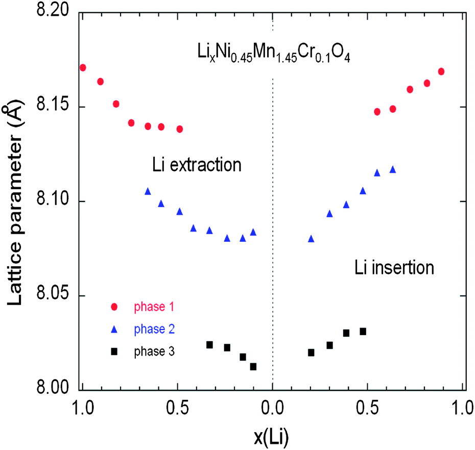 | ||
| Fig. 14 Variation of the lattice parameters of the different cubic phases in the Cr-doped LNM sample as a function of the Li concentration x during the charge (a) and discharge (b) during cycling at C/24 rate. Reproduced with permission.77 | ||
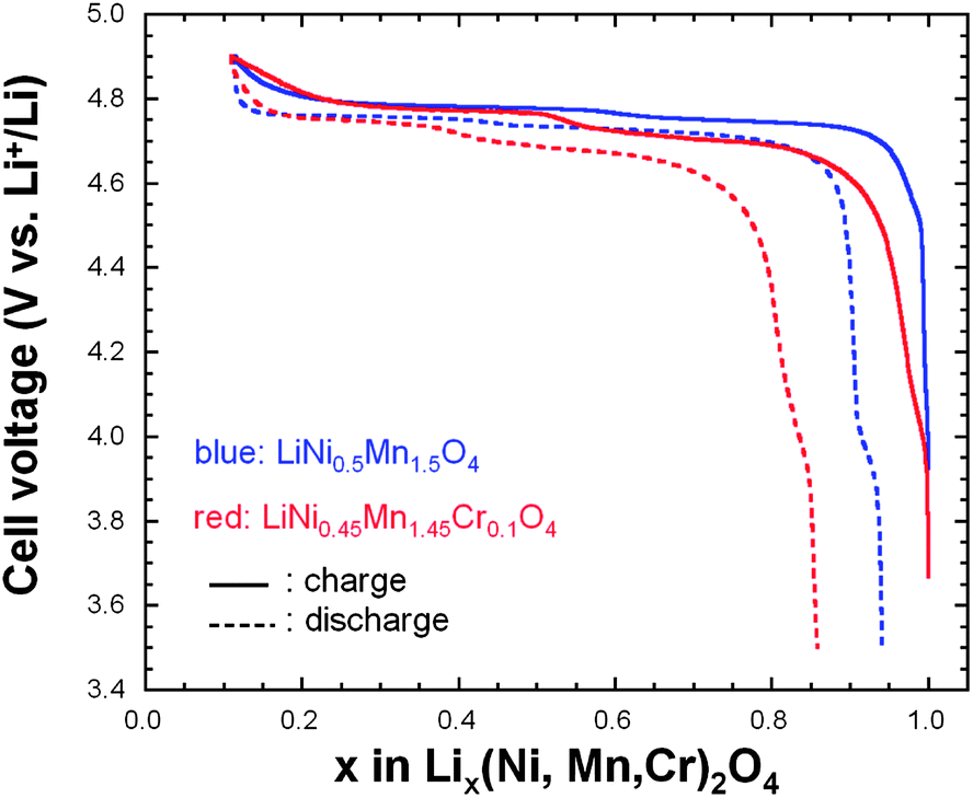
As charge proceeds from x = 1, a solid solution is observed in the whole range 1 ≤ x ≤ 0.72, the decrease in Li resulting only in the decrease of the lattice parameter of the cubic phase that we label as phase-1. A new cubic spinel phase (phase-2) started to emerge and the system thus undergoes a first-order transition at x = 0.72, to enter in a two-phase domain 0.72 ≤ x ≤ 0.54, in which the phase-2 grows at the expense of the phase-1, so that the phase-1 disappears at the Li concentration x = 0.54. Below this concentration, we find a small but finite range of concentration 0.54 ≤ x ≤ 0.37, in which the Cr-doped is again a solid solution in the phase-2 only. The system re-enters a two-phase region in the range 0.37 ≤ x ≤ 0.13 with the coexistence of phase-2 and a new phase (phase-3) that grows at the expense of phase-2. Finally, a solid solution with phase-3 only is observed in the range x ≤0.13. The experimental XRD spectra have been measured along the cycle with steps Δx ∼ 0.1, so that the uncertainty in the estimates of the Li-concentrations of the phase boundaries can be estimated to ±0.05. Upon discharge, phase-3 is found to be a solid solution up to x = 0.25. This result gives evidence that, even at the low C-rate of the experiment, thermodynamic equilibrium at the end of the charge was not reached. At the end of charge a very small faction (few% only) of phase-2 is still detectable. However, during the period of time the sample has been let in open-circuit before the cell was discharged, this phase-2 has been converted into phase-3 only. This can also be seen as the discontinuity between the end of discharge and the beginning of charge. Therefore, at equilibrium, the Cr-doped sample will be in a solid solution in phase-3 at low values of x ≤0.25. Upon discharging, the phase-2/phase-3 system is found in the range 0.26 ≤ x ≤ 0.43. The difference between 0.37 and 0.43 does not exceed the experimental uncertainty and is thus negligible. The onset of phase-1 in phase-2 is also the same at charge and discharge. Therefore, within this experimental uncertainty, we can deduce that the phase transformations are totally reversible, without any hysteresis, except for a small shift concerning the limit in the solid solution in phase-3 that, however, is not an intrinsic effect; it is clearly an artefact due to deviation from equilibrium.
To understand the link between the phase diagrams determined in the previous section and the electrochemical properties. We have reported in Fig. 15 the variation of the voltage with x for the two samples together with the range of existence of the different phases. First, we observe that the voltage of the battery with the Cr-doped sample is smaller than with the un-doped sample at any Li concentration x, except in the small region 0.1 ≤ x ≤ 0.2. The unexpected larger value of the voltage in this small region is clearly attributable to the fact that a larger proportion of phase-2 is still observed in the un-doped LNM sample in this range of concentration. Since the voltage associated to the phase-2 is lower than that of phase-3, the persistence of this phase lowers the potential, which becomes lower than in the Cr-doped sample where only the phase-3 is observed. Second, we also note that the voltage is strongly dependent of the composition in this small range of composition. This is true for the case of the Cr-doped sample, and this is expected since the Cr-doped sample is a solid solution in phase-3. In case of a two-phase regime, however, the Gibbs rule tells us that V(x) should be a flat plateau, while the potential varies very fast with x in this region. Therefore, the strong variation of V(x) in the un-doped sample in the small range 0.1 ≤ x ≤ 0.2 confirms that it is not in a two-phase regime. Instead, it should be considered as a solid solution in phase-3. The presence of the phase-2 simply means the existence of some isolated phase-2 clusters attributable to the difficulty to reach thermodynamic equilibrium.
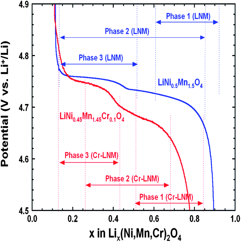 | ||
| Fig. 15 Variation of the voltage as a function of the Li concentration x in un-doped and Cr-doped LNM samples during discharge of cells cycled at C/24 rate in relation to the phase diagram. Reproduced with permission.77 | ||
G Surface modification
Despite the interesting electrochemical properties of LNM, two problems need be solved before the material may conquest the market and find a commercial development. One is the loss of oxygen. Indeed, the pressure of oxygen at thermodynamic equilibrium in all the oxides of transition metals increase linearly with the potential, favoring the loss of oxygen that causes thermal runaway and battery fires.78 The other problem comes from the proximity between the Fermi energy and the highest occupied molecular orbital (HOMO) of the carbonate electrolyte, so that a passivating solid/electrolyte-interface (SEI) layer is formed to obtain the reversible Ni(IV)/Ni(II) redox reaction.1 The surface reactions between cathode/electrolyte have been confirmed to be one of the major reasons leading to the degradation in the electrochemical performance of the 4.7 V spinel.79 Moreover, the chemical reactions with the electrolyte increase with temperature. The consequence is the important capacity fade,16 at ∼60 °C, as already noticed in the introduction, which disqualifies this battery for use in hybrid or electric vehicles. To overcome these problems, various metal oxides, carbon and phosphates80–85 have been used as surface coatings to improve the electrochemical performance of the LNM particles.More recently, we have successfully used LiFePO4 as a coating of LNM particles.86 This process allowed us to take benefit from the fact that LiFePO4 (LFP) shows very good rate performance not only at room temperature but also at 60 °C.87,88 In addition, in contrast with the transition metal oxides, the oxygen forms covalent bonding with P, to form PO4 phosphate units that are very stable, so that LFP shows an excellent thermal stability and is also stable in the battery up to a high voltage of 5.4 V. As usual with LFP, its low electrical conductivity implies that is must be carbon coated, so that the particles are multi composite, with a LNM core surrounded by a LFP coat, with conductive carbon on top of it.86Fig. 16 shows the modified Peukert plot before and after C–LFP coating. The performance at high C-rate is improved importantly in the multi-composite. This is confirmed in Fig. 17 showing a major improvement induced by the C–LFP coat on the aging of the cell upon cycling. Therefore, the C–LFP coating is a promising technology to protect the LNM particles against the reaction with the electrolyte and to prevent the oxygen loss.
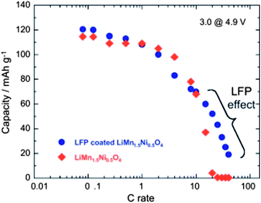 | ||
| Fig. 16 Modified Peukert plot for the Li//LMN and Li//LFP-coated LMN cells between 3.0 and 4.9 V vs. Li+/Li0. | ||
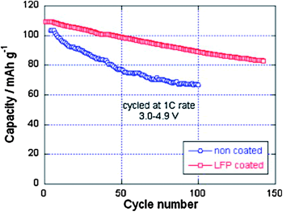 | ||
| Fig. 17 Cyclability of the Li//LMN and Li//LFP-coated LMN cells at 1 C between 3.0 and 4.9 V vs. Li+/Li0. Reproduced with permission.86 | ||
H Conclusions
The rate capability of lithium extraction/insertion is better in the disordered LNM (S.G. Fdm) phase because the electronic conductivity in this phase is several orders of magnitude larger than in the ordered phase, and because the diffusivity of lithium ions is higher. The larger electronic conductivity was attributed to the presence of oxygen vacancies in the disordered phase, but it is more likely an intrinsic property. In the stoichiometric composition of LiNi0.45Mn1.45Cr0.1O4, the cations exist as Ni2+ and Mn4+, so that they do not carry the same electronic charge. Therefore, the ordering between Mn and Ni is also a charge ordering that will result in the opening of an electrostatic gap.
The structural evolution of un-doped and Cr-doped LNM spinels in the Fdm phase as a function of the Li content (x) investigated by in situ XRD analyses shows that both charge (Li extraction) and discharge (Li insertion) reactions occur with the existence of three phases that form alternatively solid solutions and two-phase regions. The results have been understood on the basis of a model77 that takes strain effects into account, also explaining the fact that the phase diagram is sample dependent, differs between the different results reported in the literature. The analysis of the phase diagram confirms the faster dynamics of the Li-insertion/de-insertion in the Cr-doped sample, evidenced by the improved capacity retention at high C-rates. The other benefit of the Cr-substitution is the increase of the stability of the lattice. The drawback is a decrease in the energy density that is not due to a loss of capacity, but a smaller redox potential of the nickel vs. Li+/Li. Although the coating of the particles with C–LiFePO4 efficiently protects LNM against the surface reactions with the electrolyte, which was the main limiting factor for this material, making LNM the most promising material to obtain high-voltage Li-ion batteries.
References
- J. B. Goodenough and Y. Kim, Chem. Mater., 2010, 22, 587 CrossRef CAS.
- S. Sawa, S. Okada and A. Yoshino, J. Power Sources, 2001, 97–98, 430 Search PubMed.
- R. Ruffo, R. A. Huggins, C. M. Mari, M. Piana and W. Weppner, Ionics, 2005, 11, 213 CrossRef CAS.
- M. M. Thackeray, P. J. Johnson, L. A. De Picciotto, P. G. Bruce and J. B. Goodenough, Mater. Res. Bull., 1983, 18, 461 CrossRef CAS.
- J. W. Fergus, J. Power Sources, 2010, 195, 939 CrossRef CAS PubMed.
- A. Kraytsberg and Y. Ein-Eli, Adv. Energy Mater., 2012, 2, 922 CrossRef CAS.
- H. J. Bang, V. S. Donepudin and J. Prakash, Electrochim. Acta, 2002, 48, 443 CrossRef CAS.
- K. Amine, H. Tukamoto, H. Yasuda and Y. Fujita, J. Power Sources, 1997, 68, 604 CrossRef CAS.
- Y. Gao, K. Myrtle, M. J. Zhang, J. N. Reimers and J. R. Dahn, Phys. Rev. B: Condens. Matter Mater. Phys., 1996, 54, 16670 CrossRef CAS.
- S. H. Park and Y. K. Sun, Electrochim. Acta, 2004, 50, 439 CrossRef PubMed.
- R. Santhanam and B. Rambabu, J. Power Sources, 2010, 195, 5442 CrossRef CAS PubMed.
- G. Q. Liu, L. Wen and Y. M. Liu, J. Solid State Electrochem., 2010, 14, 2191 CrossRef CAS PubMed.
- B. L. Ellis, K. T. Lee and L. F. Nazar, Chem. Mater., 2010, 22, 691 CrossRef CAS.
- K. Takahashi, M. Saitoh, M. Sano, M. Fujita and K. Kifune, J. Electrochem. Soc., 2004, 151, A173 CrossRef CAS PubMed.
- Y. Terada, K. Yasaka, F. Nishikawa, T. Konishi, M. Yoshio and I. Nakai, J. Solid State Chem., 2001, 156, 286 CrossRef CAS.
- A. Manthiram, J. Phys. Chem. Lett., 2011, 2, 176 CrossRef CAS.
- G. Blasse, J. Phys. Chem. Solids, 1966, 27, 383 CrossRef CAS.
- D. Gryffroy and R. E. Vaudenberghe, J. Phys. Chem. Solids, 1992, 53, 777 CrossRef CAS.
- N. Amdouni, K. Zaghib, F. Gendron, A. Mauger and C. M. Julien, J. Magn. Magn. Mater., 2007, 309, 100 CrossRef CAS PubMed.
- J. H. Kim, S. T. Myung, C. S. Yoon, S. G. Kang and Y. K. Sun, Chem. Mater., 2004, 16, 906 CrossRef CAS.
- B. J. Hwang, Y. W. Wu, M. Venkateswarlu, M. Y. Cheng and R. Santhanam, J. Power Sources, 2009, 193, 828 CrossRef CAS PubMed.
- J. Liu and A. Manthiram, J. Phys. Chem. C, 2009, 113, 15073 CAS.
- K. J. Hong and Y. K. Sun, J. Power Sources, 2002, 109, 427 CrossRef CAS.
- Q. Zhong, A. Bonakdarpour, M. Zhang, Y. Gao and J. R. Dahn, J. Electrochem. Soc., 1997, 144, 205 CrossRef CAS PubMed.
- J. Song, D. W. Shin, Y. Lu, C. D. Amos, A. Manthiram and J. B. Goodenough, Chem. Mater., 2012, 24, 3101 CrossRef CAS.
- K. Ariyoshi, Y. Iwakoshi, N. Nakayama and T. Ohzuku, J. Electrochem. Soc., 2004, 151, A296 CrossRef CAS PubMed.
- Y. Idemoto, H. Narai and N. Koura, J. Power Sources, 2003, 119–121, 125 CrossRef CAS.
- T. Ohzuku, K. Ariyoshi and S. Yamamoto, J. Ceram. Soc. Jpn., 2002, 110, 501 CrossRef CAS.
- J. Zheng, J. Xiao, X. Yu, L. Kovarik, M. Gu, F. Omenya, X. Chen, X. Q. Yang, J. Liu, G. L. Graff, M. S. Whittingham and J. G. Zang, Phys. Chem. Chem. Phys., 2012, 14, 13515 RSC.
- K. Mukai and J. Sugiyama, J. Electrochem. Soc., 2010, 157, A672 CrossRef CAS PubMed.
- S. Patoux, L. Daniel, C. Bourbon, H. Lignier, C. Pagano, F. Le Cras, S. Jouanneau and S. Martinet, J. Power Sources, 2009, 189, 344 CrossRef CAS PubMed.
- H. S. Fang, Z. X. Wang, X. H. Li, H. J. Guo and W. J. Peng, J. Power Sources, 2006, 153, 174 CrossRef CAS PubMed.
- Z. Y. Chen, S. Ji, V. Linkov, J. L. Zhang and W. Zhu, J. Power Sources, 2009, 189, 507 CrossRef CAS PubMed.
- H. S. Fang, Z. X. Wang, X. H. Li, Z. L. Yin, H. J. Guo and W. J. Peng, Chin. J. Inorg. Chem., 2006, 22, 311 CAS.
- X. Y. Feng, C. Shen, X. Fang and C. H. Chen, Chin. Sci. Bull., 2012, 57, 4176 CrossRef CAS.
- G. Liu, L. Qi and L. Wen, Rare Met. Mater. Eng., 2006, 35, 299 CAS.
- H. S. Fang, Z. X. Wang, Z. L. Yin, X. H. Li, H. J. Guo and W. J. Peng, Trans. Nonferrous Met. Soc. China, 2005, 15, 1429 CAS.
- N. Amdouni, K. Zaghib, F. Gendron, A. Mauger and C. M. Julien, Ionics, 2006, 12, 117 CrossRef CAS PubMed.
- Z. Q. Zhao, J. F. Ma, H. Tian, L. J. Xie, J. Zhou, P. W. Wu, Y. G. Wang, J. T. Tao and X. Y. Zhu, J. Am. Ceram. Soc., 2005, 88, 3549 CrossRef CAS.
- Y. K. Fan, J. M. Wang, X. B. Ye and J. Q. Zhang, Mater. Chem. Phys., 2007, 103, 19–23 CrossRef CAS PubMed.
- T. F. Yi and Y. R. Zhu, Electrochim. Acta, 2008, 53, 3120 CrossRef CAS PubMed.
- C. Miao, L. Shi, G. Chen and D. Dai, Adv. Mater. Res., 2012, 463–464, 881 CrossRef CAS.
- S. T. Myung, S. Komaba, N. Kumagai, H. Yashiro, H. T. Chung and T. H. Cho, Electrochim. Acta, 2002, 47, 2543 CrossRef CAS.
- Q. Zhao, N. Ye, L. Li and F. Yan, Rare Met. Mater. Eng., 2010, 39, 1715 CrossRef CAS.
- H. Liu, Y. P. Wu, E. Rahm, R. Holze and H. Q. Wu, J. Solid State Electrochem., 2004, 8, 450 CrossRef CAS PubMed.
- J. H. Choy, D. H. Kim, C. W. Kwon, S. J. Hwang and Y. I. Kim, J. Power Sources, 1999, 77, 1 CrossRef CAS.
- Y. S. Lee, Y. K. Sun and K. S. Nahm, Solid State Ionics, 1998, 109, 285 CrossRef CAS.
- J. C. Arrebola, A. Caballero, L. Hernan and J. Morales, J. Power Sources, 2008, 180, 852 CrossRef CAS PubMed.
- A. Cao and A. Manthiram, ECS Symp. Abstr, 2012, vol. 2, p. 699 Search PubMed.
- Z. Q. He, L. Z. Xiong, X. M. Wu, W. P. Liu, S. Chen and K. L. Huang, Chin. J. Inorg. Chem., 2007, 23, 875 CAS.
- Y. Idemoto, H. Sekine, K. Ui and N. Koura, Electrochemistry, 2004, 72, 564 CAS.
- J. Cabana, H. Zheng, A. K. Shukla, C. Kim, V. S. Battaglia and M. Kunduraci, J. Electrochem. Soc., 2011, 158, A997 CrossRef CAS PubMed.
- M. Kunduraci and G. G. Amatucci, J. Electrochem. Soc., 2006, 153, A1345 CrossRef CAS PubMed.
- D. Liu, J. Han and J. B. Goodenough, J. Power Sources, 2010, 195, 2918 CrossRef CAS PubMed.
- M. Yamada, B. Dongying, T. Kodera, K. Myoujin and T. Ogihara, J. Ceram. Soc. Jpn., 2009, 117, 1017 CrossRef CAS.
- H. M. Wu, J. P. Tu, X. T. Chen, D. Q. Shi, X. B. Zhao and G. S. Cao, Electrochim. Acta, 2006, 51, 4148 CrossRef CAS PubMed.
- Y. K. Sun, G. S. Park, Y. S. Lee, M. Yoshio and K. S. Nahm, J. Electrochem. Soc., 2001, 148, A994 CrossRef CAS PubMed.
- S. H. Park, S. W. Oh, S. T. Myung, Y. C. Kang and Y. K. Sun, Solid State Ionics, 2005, 176, 481 CrossRef CAS PubMed.
- T. Ogihara, T. Kodera, K. Myoujin and S. Motohira, Mater. Sci. Eng., B, 2009, 161, 109 CrossRef CAS PubMed.
- T. A. Arunkumar and A. Manthiram, Electrochim. Acta, 2005, 50, 5568 CrossRef CAS PubMed.
- G. B. Zhong, Y. Y. Wang, Y. Q. Yu and C. H. Chen, J. Power Sources, 2012, 205, 385 CrossRef CAS PubMed.
- D. Liu, Y. Lu and J. B. Goodenough, J. Electrochem. Soc., 2010, 157, A1269 CrossRef CAS PubMed.
- D. W. Shin and A. Manthiram, Electrochem. Commun., 2011, 13, 1213 CrossRef CAS PubMed.
- D. Liu, J. Hamel-Paquet, J. Trottier, F. Barray, V. Gariépy, P. Hovington, A. Guerfi, A. Mauger, C. M. Julien, J. B. Goodenough and K. Zaghib, J. Power Sources, 2012, 217, 400 CrossRef CAS PubMed.
- M. Kunduraci, J. F. Al-Sharab and G. G. Amatucci, Chem. Mater., 2006, 18, 3585 CrossRef CAS.
- X. Ma, B. Kang and G. Ceder, J. Electrochem. Soc., 2010, 157, A925 CrossRef CAS PubMed.
- J. H. Kim, C. S. Yoon, S. T. Myung, J. Prakash and Y. K. Sun, Electrochem. Solid-State Lett., 2004, 7, A216 CrossRef CAS PubMed.
- M. Kunduraci and G. G. Amatucci, J. Power Sources, 2007, 165, 359 CrossRef CAS PubMed.
- P. Strobel, A. Ibarra-Palos, M. Anne and F. Le Cras, J. Mater. Chem., 2000, 10, 429 RSC.
- T. Nakamura, Y. Yamada and M. Tabuchi, J. Appl. Phys., 2005, 98, 93905 CrossRef.
- J. B. Goodenough, Magnetism and the Chemical Bond, Wiley, New York, 1963 Search PubMed.
- F. G. B. Ooms, E. M. Kelder, J. Schoonman, M. Wagemaker and F. M. Mulder, Solid State Ionics, 2002, 152, 143 CrossRef.
- D. W. Shin and A. Manthiram, Electrochem. Commun., 2011, 13, 121 CrossRef PubMed.
- L. Wang, H. Li, X. Huang and E. Baudrin, Solid State Ionics, 2011, 193, 32 CrossRef CAS PubMed.
- K. Rhodes, R. Meisner, Y. Kim, N. Dudney and C. Daniel, J. Electrochem. Soc., 2011, 158, A890 CrossRef CAS PubMed.
- B. Hai, A. K. Shukla, H. Duncan and G. Chen, J. Mater. Chem. A, 2013, 1, 759 CAS.
- W. Zhu, D. Liu, J. Trottier, C. Gagnon, A. Mauger, C. M. Julien and K. Zaghib, J. Power Sources, 2013, 242, 236–243 CrossRef CAS PubMed.
- R. A. Huggins, J. Electrochem. Soc., 2013, 160, 3001 CrossRef PubMed.
- J. Liu and A. Manthiram, Chem. Mater., 2009, 21, 1695 CrossRef CAS.
- Y. K. Sun, K.-J. Hong, J. Prakash and K. Amine, Electrochem. Commun., 2002, 4, 344 CrossRef CAS.
- T. Noguchi, I. Yamazaki, T. Numata and M. Shirakata, J. Power Sources, 2007, 174, 359 CrossRef CAS PubMed.
- Y. K. Sun, Y. S. Lee, M. Yoshio and K. Amine, Electrochem. Solid-State Lett., 2002, 5, 99 CrossRef PubMed.
- Y. Kobayashi, H. Miyashiro, K. Takei, H. Shigemura, M. Tabuchi, H. Kageyama and T. Iwahori, J. Electrochem. Soc., 2003, 150, 1577 CrossRef PubMed.
- J. Y. Shi, C.-W. Yi and K. Kim, J. Power Sources, 2010, 195, 6860 CrossRef CAS PubMed.
- H. M. Wu, I. Belharouak, A. Abouimrane, Y.-K. Sun and K. Amine, J. Power Sources, 2010, 195, 2909 CrossRef CAS PubMed.
- D. Liu, J. Trottier, P. Charest, J. Fréchette, A. Guerfi, A. Mauger, C. M. Julien and K. Zaghib, J. Power Sources, 2012, 204, 127 CrossRef CAS PubMed.
- C. Zhu, Y. Yu, L. Gu, K. Weichert and J. Maier, Angew. Chem., Int. Ed., 2011, 50, 6278 CrossRef CAS PubMed.
- K. Zaghib, N. Ravet, M. Gauthier, F. Gendron, A. Mauger, J. B. Goodenough and C. M. Julien, J. Power Sources, 2006, 163, 560 CrossRef CAS PubMed.
| This journal is © The Royal Society of Chemistry 2014 |